18. System Integration in my Wave Flume
Initial idea
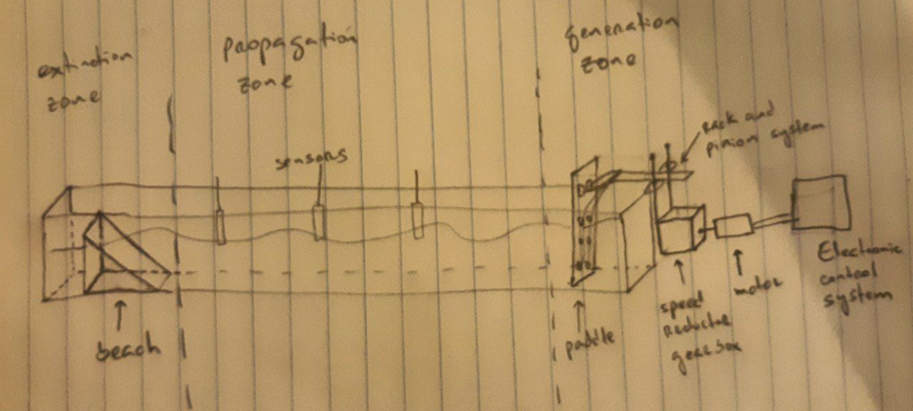
My initial idea consisted of creating a wave flume by applying as many Fab Lab techniques as possible and allowing experiments on fluid dynamics, sedimentation and complex systems. The tasks that I proposed initially on my final project are:
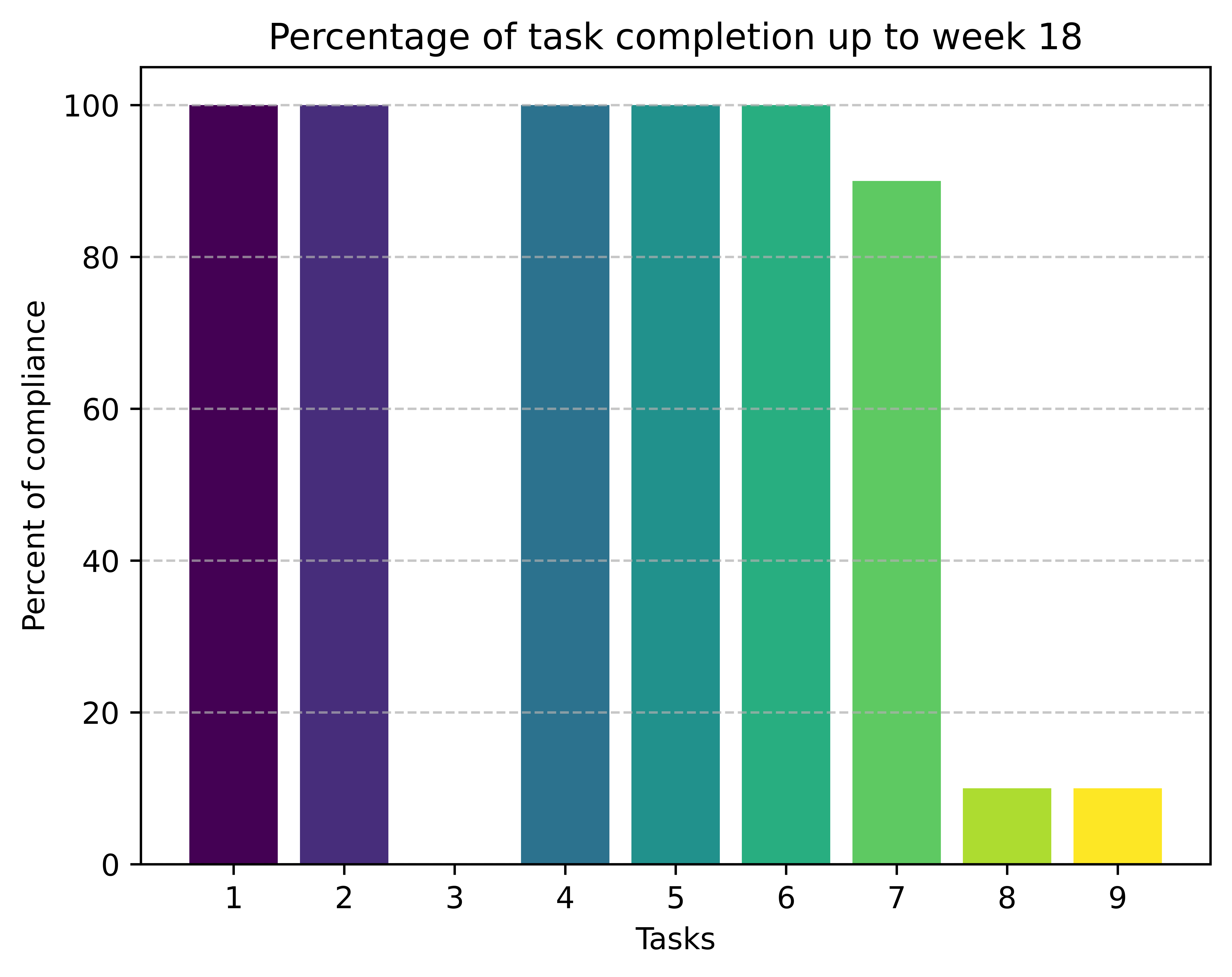
- Use a 2D design software to create a logo for the identification of the wave flume.
- Use 2D design and laser cutting to make the paddle of the wave generator.
- Assemble the container of the wave flume.
- Use 3D design and 3D printing to make the structure of the wave generator.
- Design a PCB on KiCAD, milling it and soldering it, to control the movement of the wave generator.
- Programming with a simple code a microcontroller places it on the PCB designed to control the movement of the wave generator.
- Assemble the wave generator of the wave flume.
- Perform some tests without water and with water with two different filling levels.
- Do some initial fluid mechanics experiment designs to use the wave flume.
What tasks have been completed?
At the end of this week, 5 of the 9 tasks proposed to be performed in the final project were completed, as shown in the following graph:

Logo designed on week 16 using InkScape. The logo represents the three types of wave classifications according to relative depth in Airy's Linear Wave Theory: deep waves, waves of intermediate depth, and waves of shallow depths. It also includes the names of the three entities linked to the project that has allowed me to take the Fab Academy 2024 here in Brussels: Académie de Recherche et d'Enseignement Supérieur (ARES), the Université Libre de Bruxelles (ULB), and the University of Havana (UH).
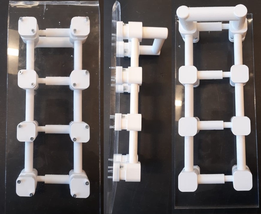
Initial design of paddle of the wave flume. This paddle was made up of two parts. The first was made of acrylic and was designed and laser cut during week 3. The second was made up of three pieces designed in FreeCAD and 3D-printed on week 5. This design was discarded after a visit to the Ghent University's Tech Lane Ghent Science Park, especially to the civil engineering deparment, led by Professor Peter Troch. This exchange allowed me to realize what line current researchers follow when designing paddle-type wave generators for wave flumes.

Final design of paddle of the wave flume. The round cuts of superior sides were made for two reasons: reduce the weight of the paddle and contribute to the easy cut of the laser cutter. Los cinco hoyos centrales se hicieron siguiendo los de la tuerca que permite su unión con el tornillo sinfin que constituye el eje del servomotor. Los cuatro hoyos laterales fueron realizados para unir la paleta a los ejes paralelos que servirán de guía a la paleta asegurando un movimiento paralelo a las paredes laterales del canal de olas. El ancho de la paleta es 2 mm menor al ancho interior del canal de olas. Los bordes no son redondeados para minimizar el área que no cubre la paleta dento de la sección transversal del canal de olas.
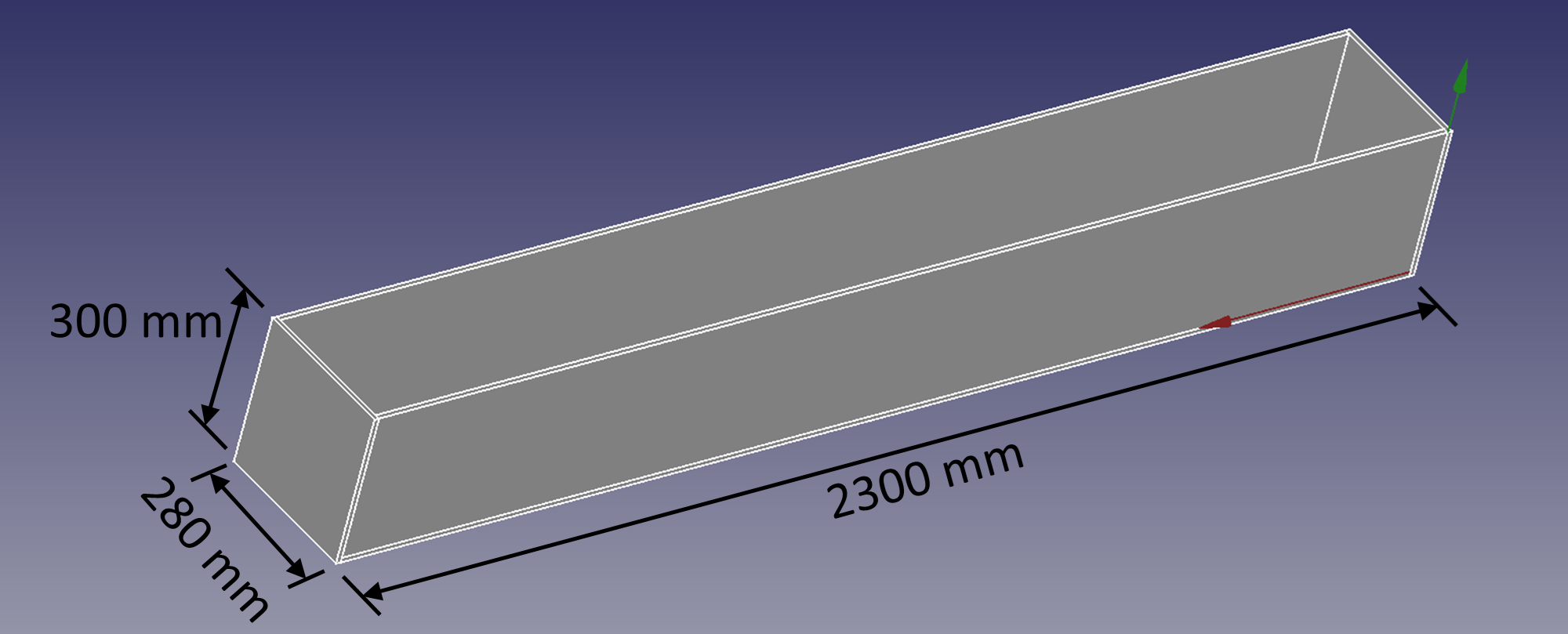
Here you can see the dimensions of the wave flume container. The acrylic sheets were bought on week 17, but in this week, I don't have it.
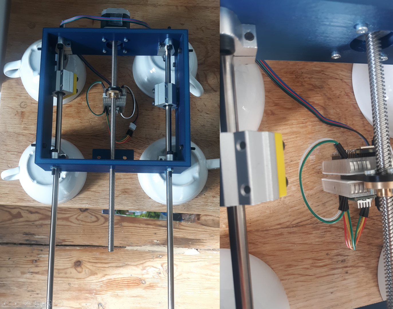
Tha base of the wave generator was designed on week 12.
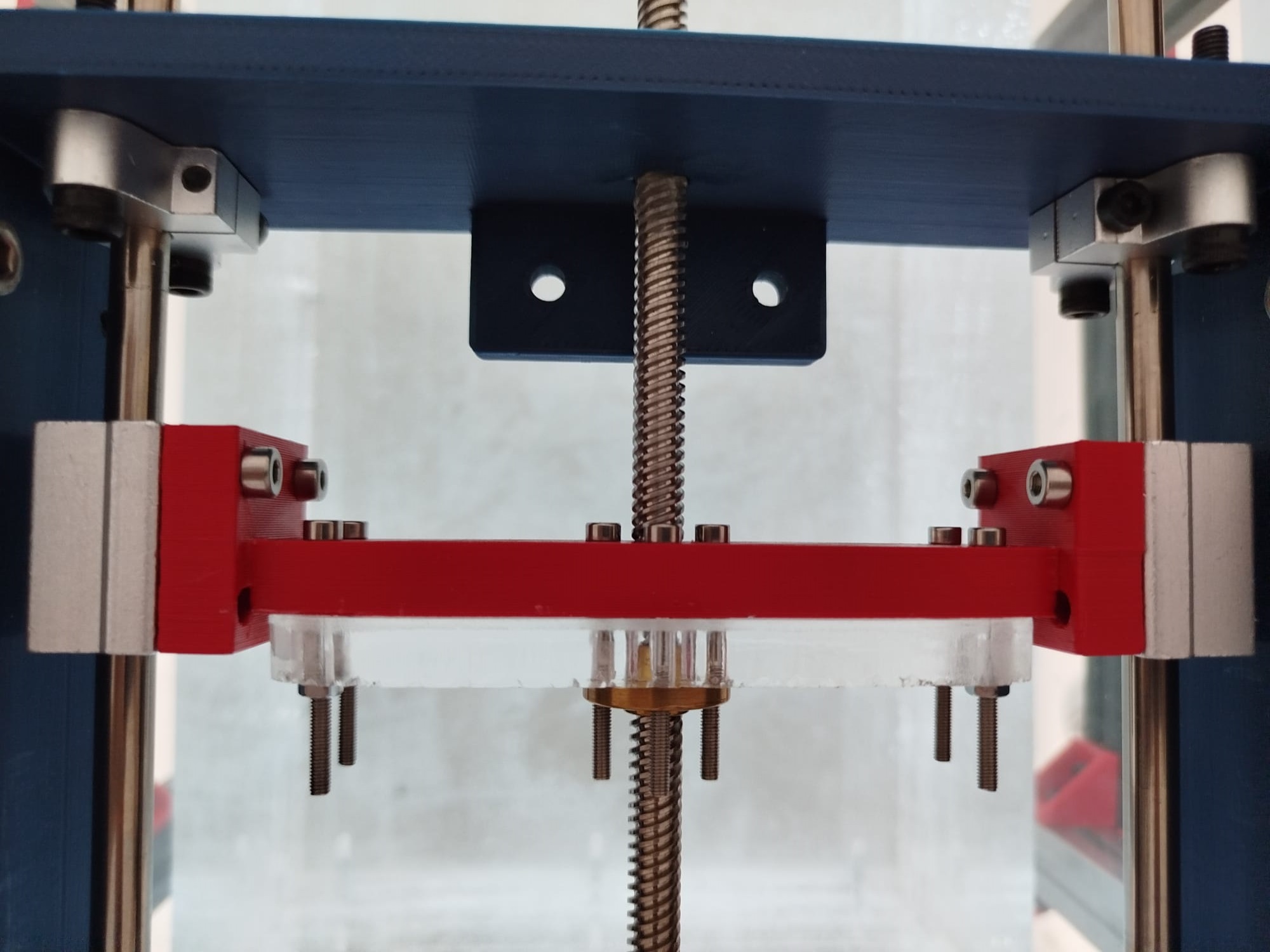
Piece used to align the parallel axis with the screw of the servomotor.
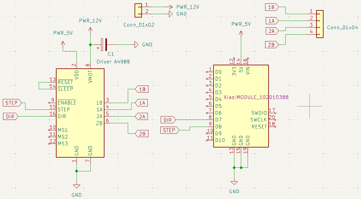
Schematic of the board disegned on KiCAD to control the wave generator. Include the microcontroller, the driver and the connectors, showing the integration of the electronic part at the project.
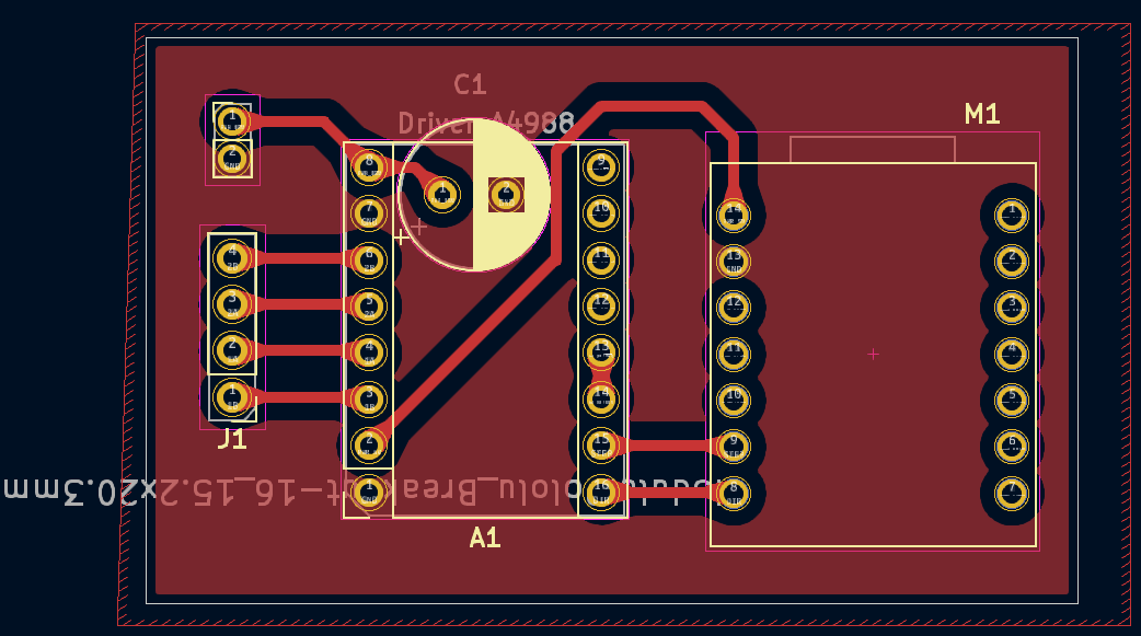
PCB part of the board disegned on KiCAD to control the wave generator.
Process of milling and soldering of the board used to control the servomotor.
          #include <Arduino.h>
          #include "BasicStepperDriver.h"
          #define MOTOR_STEPS 200
          #define RPM 120
          #define MICROSTEPS 1
          #define DIR 4
          #define STEP 7
          int LEN = 720;

          BasicStepperDriver stepper(MOTOR_STEPS, DIR, STEP);

          void setup()
          {
            stepper.begin(RPM, MICROSTEPS);
          }

          void loop()
          {
            stepper.rotate(LEN);
            stepper.rotate(-LEN);
            delay(50);
          }
Simple programming code of the microcontroller with Arduino IDE to control the speed and the frecuency of the wave generator. After this step the wave generator is fully assembled and ready to make some test. This part close the mechanic and electronic integration of the project.
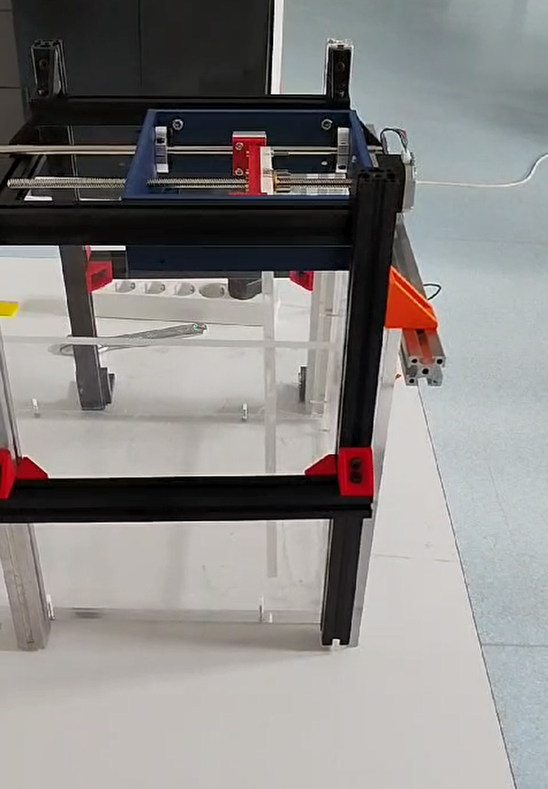
Mechanical parts of the wave generator assembled.
What tasks remain?
There are still some work to be done:
- Assemble the wave flume container, when the acrylic sheets arrives to Fab Lab ULB.
- Perform tests with the wave generator. These tests are already planned and it only remains to execute them when the wave flume container is assembled.
- Perform experiments with the flume. These are in the planning phase and will be executed when the wave flume container is assembled.
What questions need to be resolved?
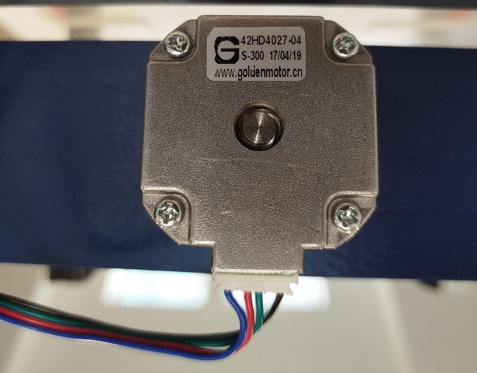
The servomotor used has a maximum speed of 120 revolution per minutes (RPM), because they are design to be used on 3D-printer and CNC machines. This range of speed is a restriction for my wave generator so in the future I will have think in a solution to increase the range.
What have you learned?
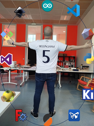
This final project and the Fab Academy were for me a very exciting and challenging experience. The skills I created on Fab Lab techniques on these 6 months make me a better experimental physicist, because right now I know how to use the tools to make (almost) anything.