3. Computer-Controlled Cutting
Computer-controlled cutting technology represents a manufacturing process that employs computer-controlled machines to cut materials with precision and efficiency. The utility of computer-controlled cutting lies in its capacity to produce exact, consistent cuts in a diverse array of materials, including metals, plastics, wood, and textiles. Computer-controlled cutting facilitates the creation of meticulously crafted parts and components that are challenging to attain through conventional cutting techniques.
Research
This week, we will cover two types of computer-controlled cutting:
- Laser cutting
- Vinyl cutting
Computer-controlled cutting with carbon dioxide (CO2) laser machines is a highly efficient and versatile state-of-the-art technique in the manufacturing industry. This method utilizes a CO2 laser to make precise cuts in a wide variety of materials, including metal, wood, acrylic, leather, and other non-metallic materials. The CO2 laser machine operates by emitting a highly concentrated laser beam that is focused on the material to be cut. The material is heated and vaporized at the designated point, resulting in a precise and clean cut. The computer controls the direction and intensity of the laser, enabling customized cuts based on the programmed design. This process ensures high precision and repeatability in part production, leading to improved manufacturing efficiency and quality.
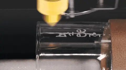
Image taken for: https://creativalab.io/products/accesorio-rotatorio-para-beamo
Laser cutting
In order to utilize the laser cutting machine, I initially conceived of creating a preliminary iteration of the wave flume palette, which will ultimately serve as the foundation for my Final Project.
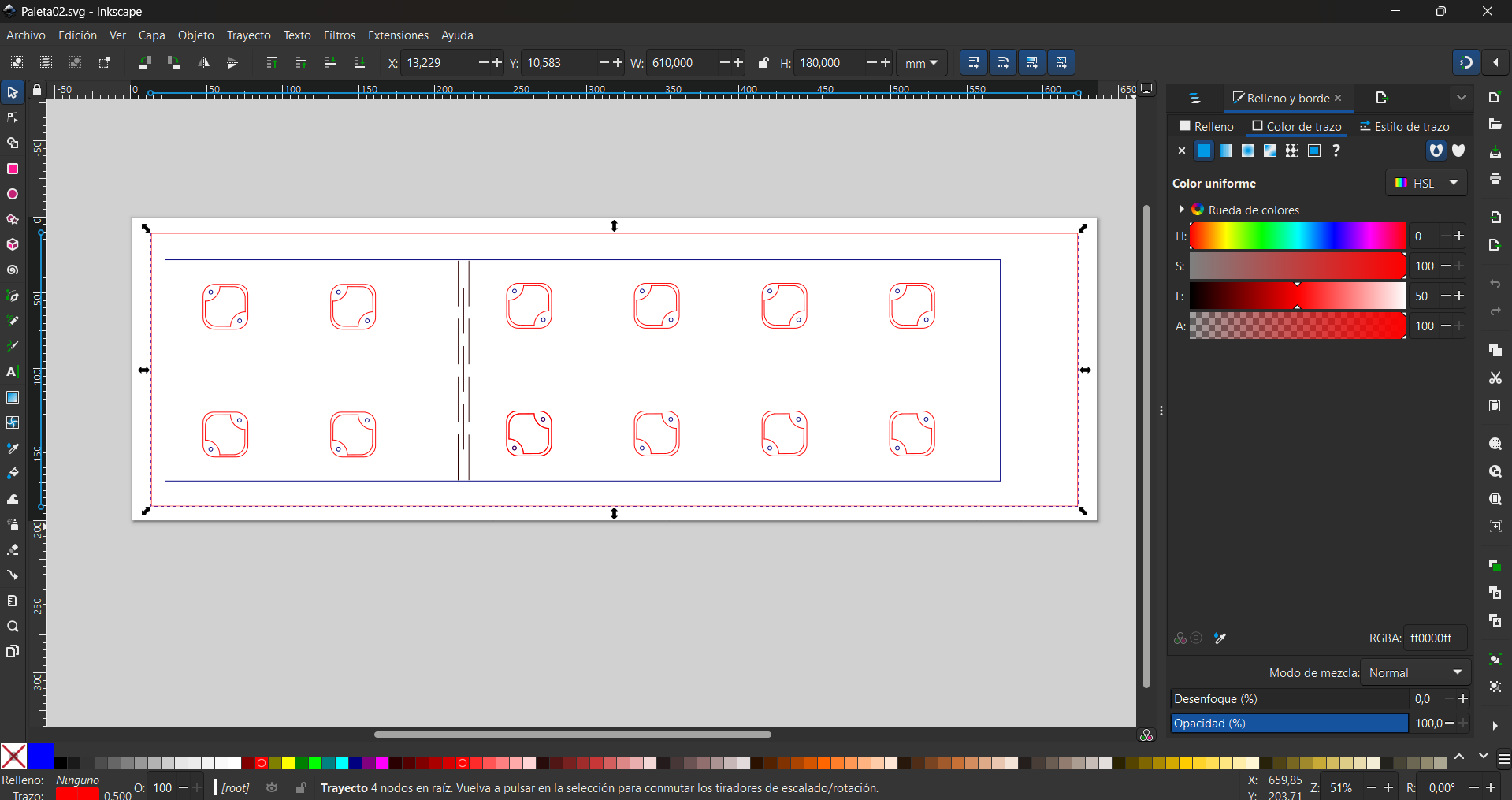
The design of the paddle was created in InkScape and exported as a .svg file.

The initial design of the palette, with reference to the supports to be incorporated in week 5.
The palette design can be downloaded here:
The ULB Fab Lab contains two laser cutting machines: the Epilog Laser Fusion Pro and the Lasersaur. The Epilog Laser Fusion Pro is a professional machine with its own software. In contrast, the Lasersaur was designed and assembled by the members of the Fab Lab ULB, in collaboration with a web controller.
To cut the palette, the Lasersaur was employed, as it possesses greater cutting power than other available options.
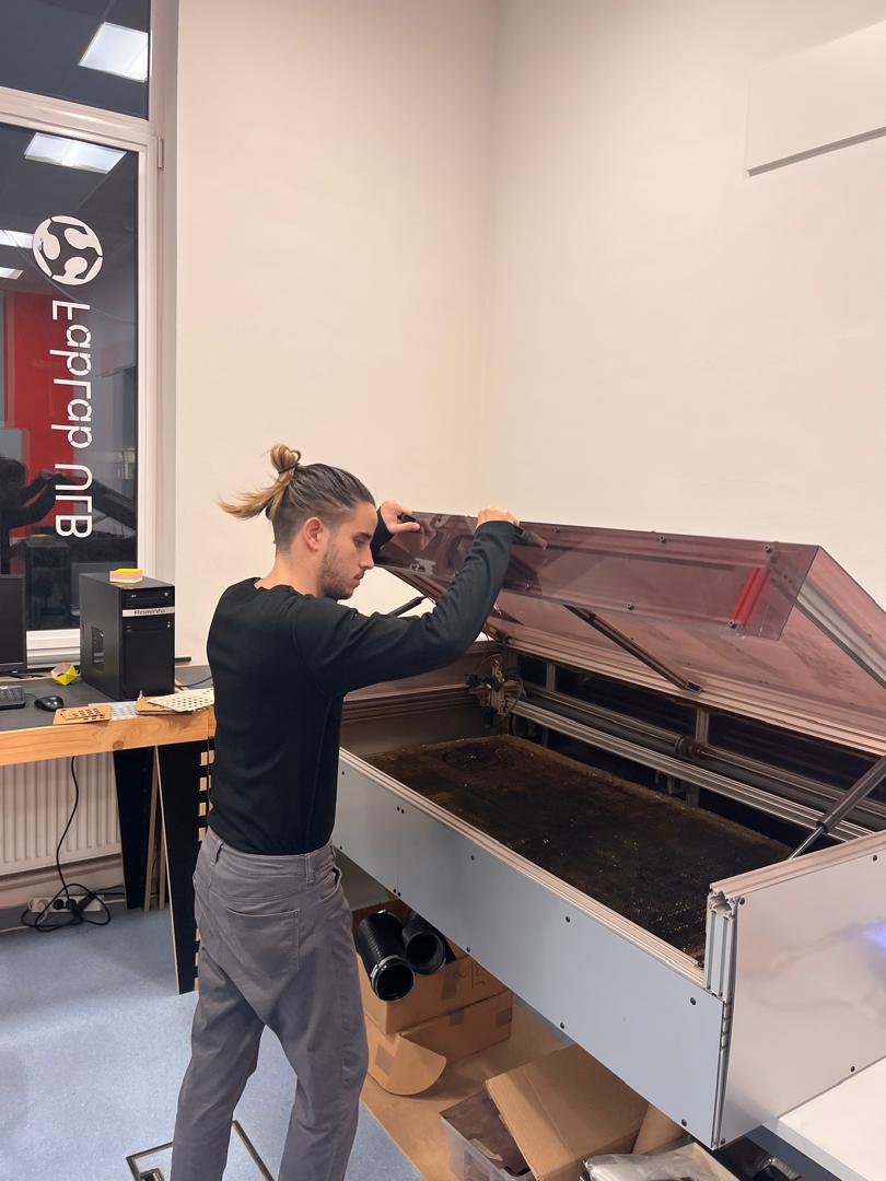
Alex Manuel Rivera Rivera operating the Lasersaur.
To operate Lasersaur, the following steps must be followed:
- Firstly, it is imperative that the extractors and nozzle compressor are activated. These measures are fundamental to the prevention of inadvertent fires or the accumulation of harmful gases within the operational environment.
- Subsequently, the file must be uploaded to the machine and the web user interface must be opened to control it. The process is relatively straightforward and allows the modification of three cutting parameters: power, speed, and the number of times cutting occurs. Instructions on how to modify these parameters can be found in this week's group assignment.
- Ultimately, the cutting is conducted while the machine is operational within the room. In the event of an emergency, the emergency stop button on the machine must be activated.
Because the thickness of the acrylic I used was 1 cm, it required the laser power to be at maximum and the speed to be very low (15% of maximum speed) to make the cut in two passes.
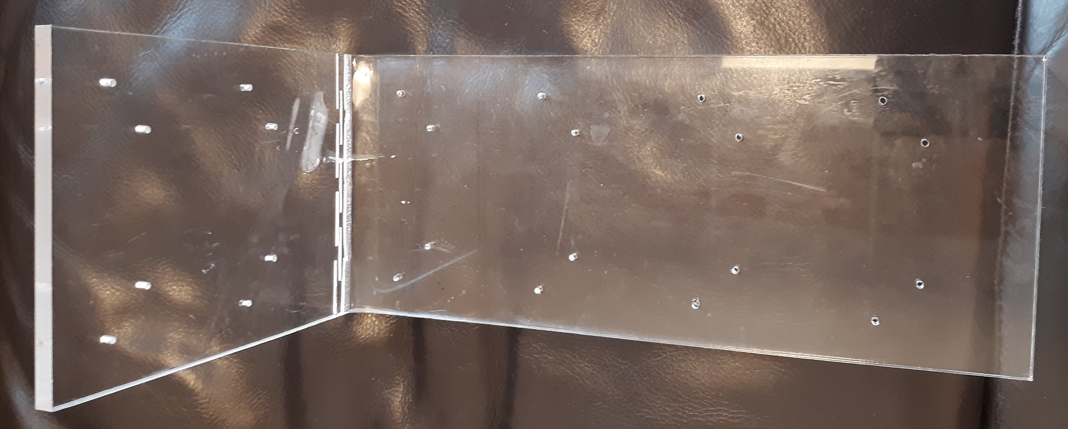
The resulting cut can be observed in the accompanying image.

Following the application of heat to the paddle using a heat gun in order to conform to the broken lines of the design, the following result was obtained.
In creating the press-fit, I selected OpenSCAD as the software for designing the metric model, as all designs created with this software are parametric. This allows for straightforward adjustment of the dimensions and features of the model according to the user's specifications. I made a box with a serrated closure to make a tight and secure seal, which is essential for the press-fit function. The design of the housing means that the parts fit perfectly and stay reliably in place. In this case, we needed a three-sided design because the parallel faces of the octohedrons that make up the box are identical. You can see the results below.
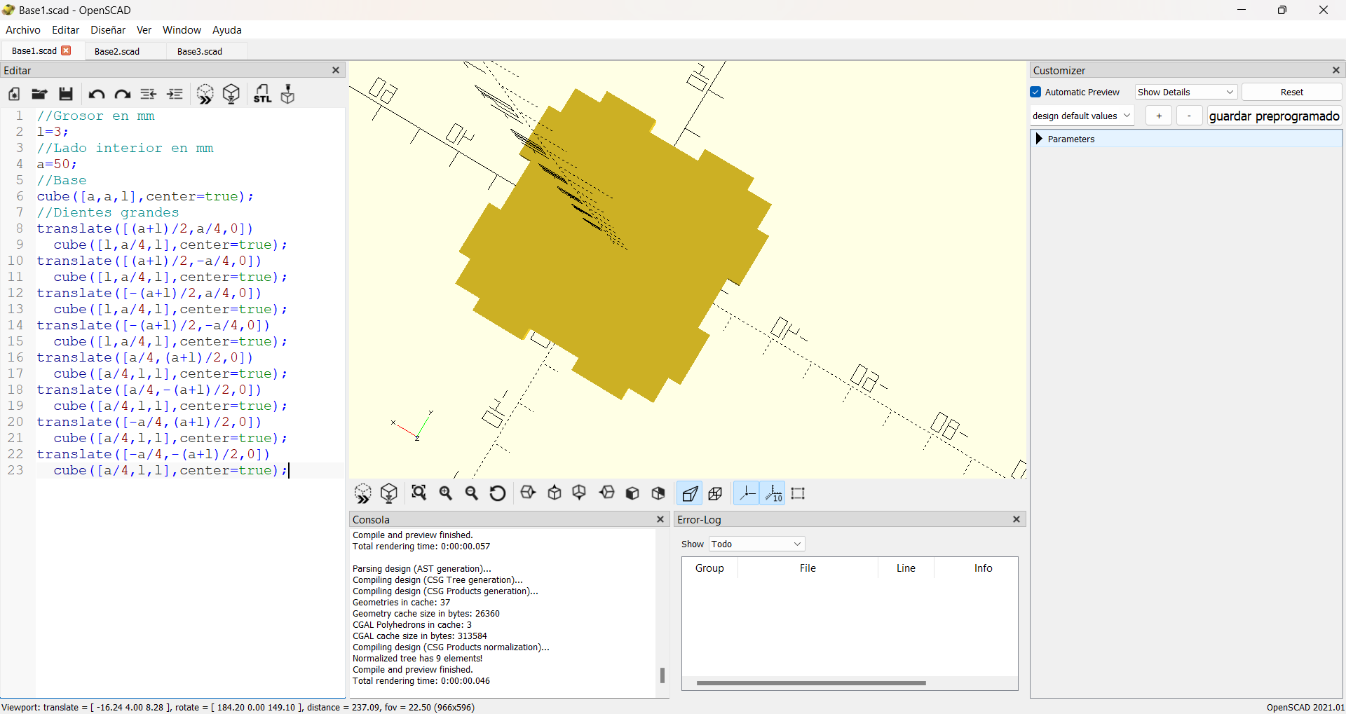
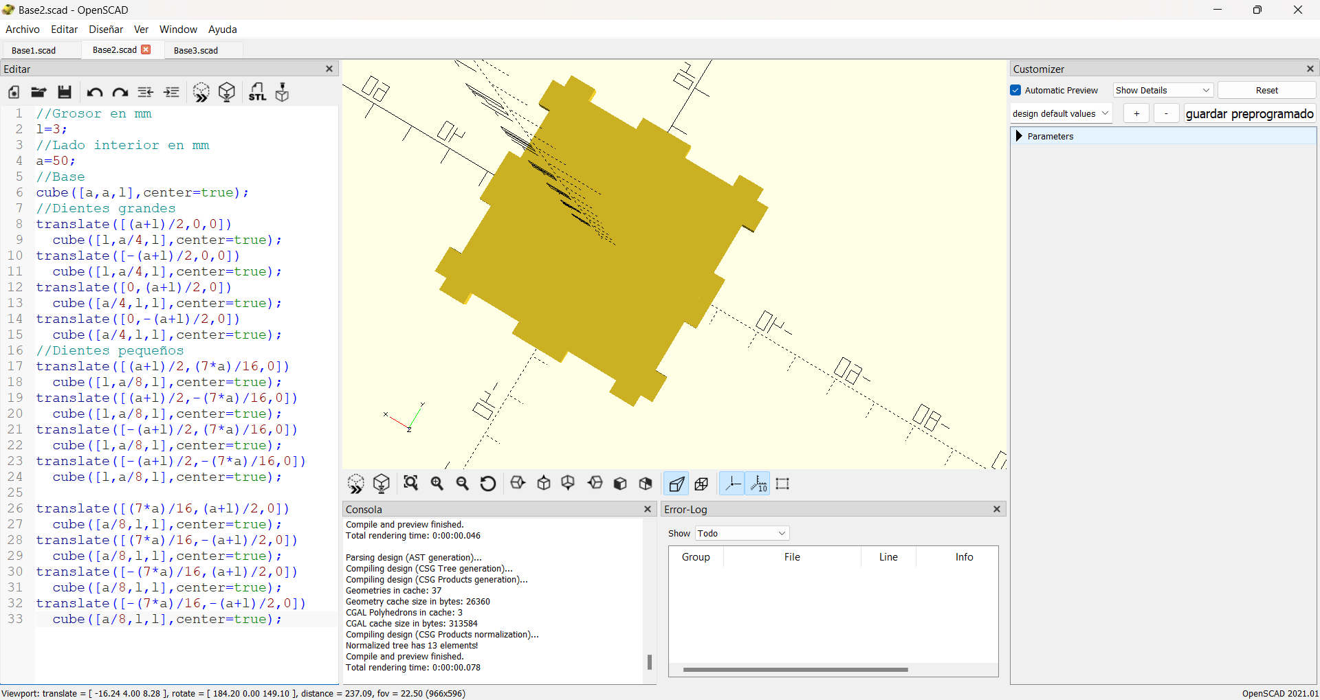
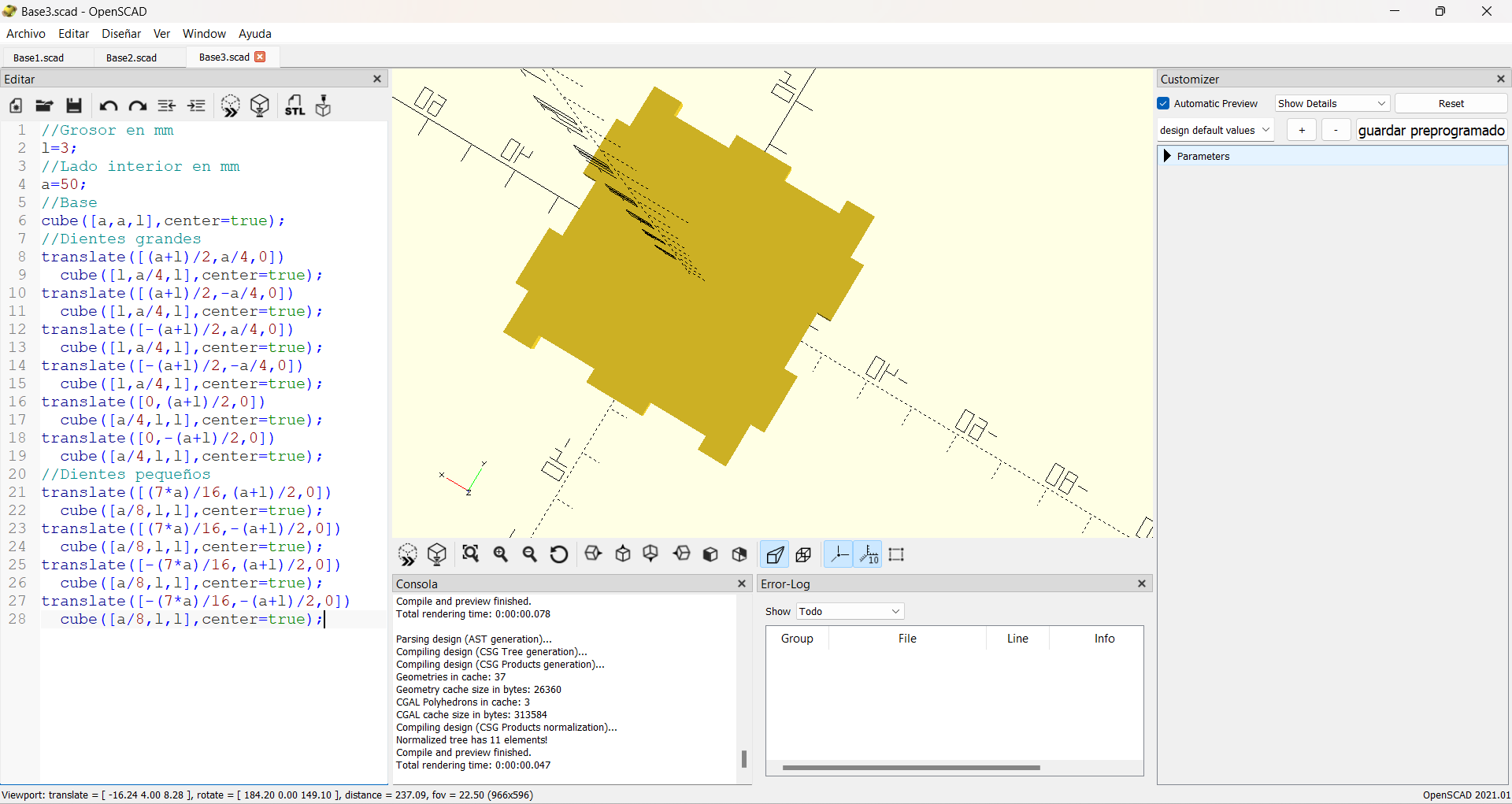
The subsequent image illustrates the outcome of the design for the incision in a vector format.

The subsequent button allows the user to download all the requisite files for the construction of the box.
The video below illustrates the cutting process.
This is the final result.

Vinyl cutting
In order to utilise the vinyl cutter machine (Silhouette Cameo® 3), files in the .dxf (Drawing Exchange Format) must be loaded. This can be accomplished with relative ease through the use of InkScape. Initially, the design is created and subsequently saved in this format. For the purposes of this experiment, I elected to create an overlay template for an electronic board, with the intention of applying a protective layer of paint. The results and the step-by-step of this procedure can be seen in the documentation of week 4.