My Final Project: Wave flume
The objective of this project is to design and build a small wave flume with FabLab techniques.

Slide showing a collage that illustrates all the FabLab techniques used.
Previous experiences:
One of the central tenets of my master's thesis was the design, construction, and characterization of a wave flume utilizing recycled materials, low-cost electronics, and image recognition. This was essential due to the challenging "high tropicallity conditions" inherent to conducting scientific research in Cuba.
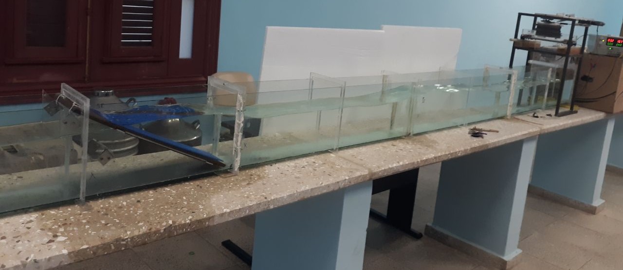
First Wave Flume of the University of Havana
Background:
Wave flumes are facilities for the simulation of wave or sea conditions, where their length is at least one order of magnitude larger than the width and height. This allows them to be used for quasi-2D fluid simulations. The most general description of the fluids is by means of the Navier-Stokes equations, which are nonlinear partial differential equations. For simpler cases, such as a wave flume with sine waves, Airy's Linear Wave Theory is a viable alternative.
Wave flumes can be divided into three distinct zones:
Generation zone: It is located at one end of the channel and, as its name suggests, is where the wave formation takes place. The elements that make up this part are the wave generator paddle, the electromechanical system and the electronic control system.
Propagation zone: This section of the wave flume is the longest. This is since the waves generated in the generation section must be properly developed, for which space is required. In this zone, it is possible to observe the evolution of the wave, its profile, and its development along the wave flume. This is the part of the wave flume where the sensors, buoys and other measuring devices are located.
Extinction zone: It corresponds to the end of the wave flume opposite to the generation zone. There are basically two types of absorption systems: active and passive. The active systems work with control algorithms that make the movement of the generator modified according to the height of the wave that arrives and superimposes a movement to the own movement of the generation. Passive systems consist of structures that act as a beach, absorbing the waves so that they are not reflected on the back wall of the wave flume.
Initial Idea
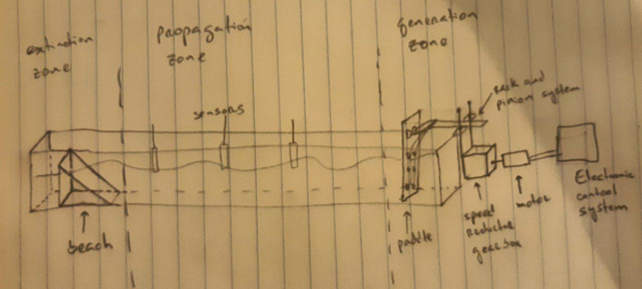
Initial sketch used for wave flume design
Initial conceptual description: The wave flume that is to be designed and constructed will have a length of three meters, a height of thirty centimeters, and a width of twenty centimeters. Its walls will be constructed from acrylic sheets that are at least one centimeter thick. The wave generator will be a piston-type with horizontal movement. It will be constructed from a rectangular acrylic sheet measuring 35 by 18 centimeters and with a thickness of at least 10 millimeters. Various systems for converting rotation into translation, such as the connecting rod and crank system, and the pinion and toothed wheel system, will be tested for its mechanical connection with the electric motor. Additionally, all components of this connection system will be designed and constructed using acrylic or 3D printing. Selecting the appropriate motor for the project is a complex task, as it requires a high-torque electric motor that can operate for at least 15 minutes without overheating. To achieve the necessary torque, a speed reducer box will be utilized. However, it is uncertain whether existing digital fabrication techniques at the Fab Academy can produce a speed reducer box with the required precision. A 3D-printed beach will be constructed in the wave flume's extinction zone. The study will assess various profiles and hole configurations to increase turbulence on the beach, reducing the energy of the waves that pass through it and, consequently, the energy of the waves reflected at the back of the wave flume. Sensors will be placed in the propagation zone of the wave flume to characterize the state of the system. The sensors will measure magnitudes such as wavelength, frequency, and amplitude of the waves generated. The type of sensors to be used will be designed along the way.
Project description:
Logo of the Wave Flume:
To distinguish our wave flume, during week 16, I designed a logo using InkScape. The logo represents the three types of wave classifications according to relative depth in Airy's Linear Wave Theory: deep waves, waves of intermediate depth, and waves of shallow depths. It also includes the names of the three entities linked to the project that has allowed me to take the Fab Academy 2024 here in Brussels: Académie de Recherche et d'Enseignement Supérieur (ARES), the Université Libre de Bruxelles (ULB), and the University of Havana (UH).

2D design technique
Container:
The structure is composed of 10 mm thick acrylic sheets, with an interior dimension of 2.3 meters long, 30 centimeters high, and 28 centimeters wide. The sheets are joined using 20 mm long socket head cap screws M4 and DowSil 781 multi-purpose silicone sealant-clear.
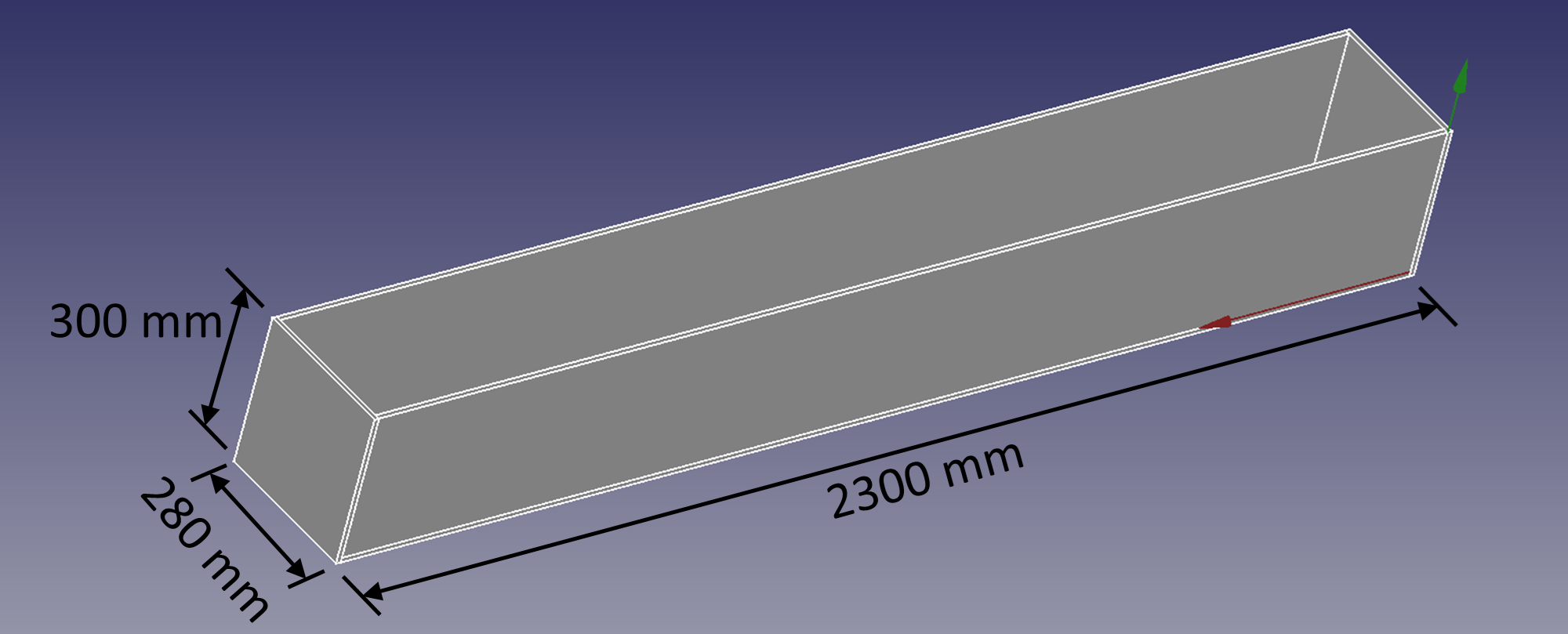
Dimensions of the container.
The assembling of the container was the harder and most demandant part of the final project. Even when the acrylic sheets were cut previously, 'cause we select the dimensions in the web page of the seller (as can be seen on week 17), the placement of the sheets at a 90 degree angle with perfect alignment between its implied harder hands-work and a meticulous planification of the process. First, I placed a lateral sheet on vertical position and put the button sheet aligned as show the fallowing image:
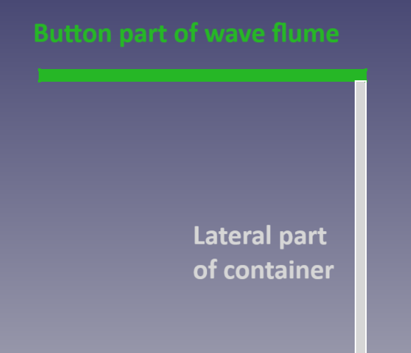
First step to assemble the container.
After that I drilled 10 holes of 3.5 mm diameter with a drill, and thread each of them using a tap. In such way, the acrylic plates were firmly attached, with a low possibility of breaking up. Subsequently, I repeated the same process with the next lateral acrylic sheet. Finally, I place the end and finish acrylic sheets with an identical procedure. The following image shows the fully assembled container.

Two views of the container of the wave flume
Mechanical parts of the Wave Generator:
The wave generator was constructed on a 3D-printed square base, which allows the motor and two guides parallel to its axis, with their respective carriages, to be attached. This base was fabricated on week 12. The motor is a NEMA 17 42HD4027-04 stepper motor with a fixed external trapezoidal linear screw, to which a nut with four anchor holes was attached. This nut is attached to the vane by means of four M3 socket head cap screws. The pallet is constructed from a 10 mm thick acrylic sheet and is attached to the guide carriages by a 3D-printed component. The entire structure is supported on aluminum profiles.

Different views of the mechanical parts of the wave generator. The image shows the use of 3D printing and laser cutting techniques.
All the files to replicate the mechanical parts of the wave generator can be downloaded here:
Electrical parts of the Wave Generator:
The electrical components of the wave generator consists of a Seeed Studio Xiao RP2040 microcontroller, which controls the operation of the servomotor, an A4988 driver (Pololu), and a 9 V power supply, placed on a board designed in KiCAD, as shown in the following figure.
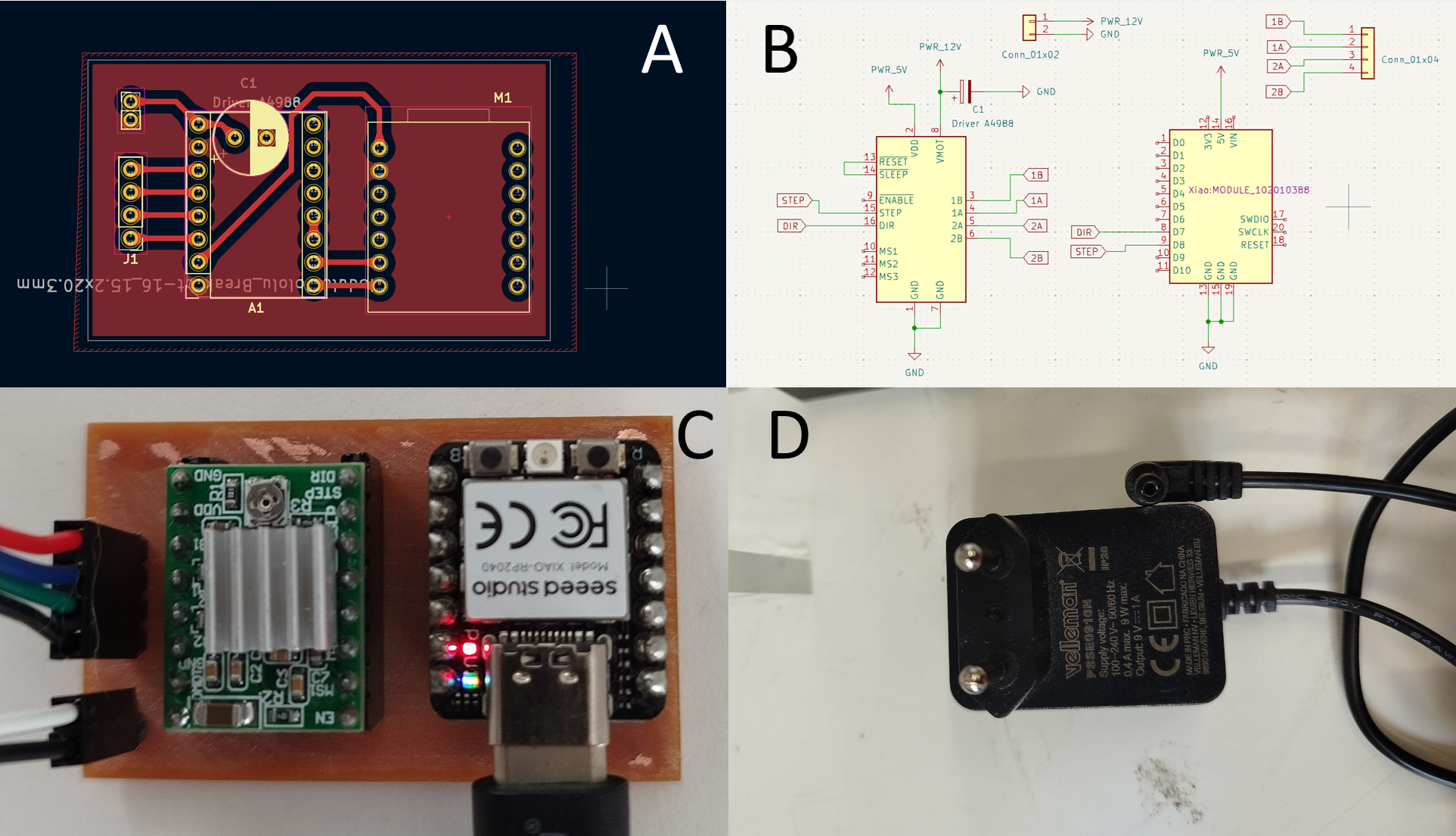
Different electrical and electronic components of the wave generator. A: PCB on KiCAD of the board disegned, B: Schematic on KiCAD of the board disegned, C: Board finished (milled, soldered and mounted the components) and working, D: Power supply used. This part evidence the electric design and production techniques.
Milling and soldering the board.
All the files to replicate the board of the wave generator can be downloaded here:
Programming
The use of the A4988 driver and shield facilitates the programming process, as it is relatively straightforward. Furthermore, the incorporation of libraries for stepper motor control using two-pin drivers further simplifies the programming process. In this case, the StepperDriver library was employed, with one of the default examples modified. This code enables the user to vary the period, length, and speed of the paddle oscillations, the most important parameters of a wave generator. It is important to note that the motor in question is a common component found in 3D printers and CNC machines. Consequently, its speed is not particularly high.
#include <Arduino.h>
#include "BasicStepperDriver.h"
#define MOTOR_STEPS 200
#define RPM 120
#define MICROSTEPS 1
#define DIR 4
#define STEP 7
int LEN = 720;

BasicStepperDriver stepper(MOTOR_STEPS, DIR, STEP);

void setup()
{
  stepper.begin(RPM, MICROSTEPS);
}

void loop()
{
  if(Serial.available()){
    int ReadC = Serial.read();
    if(ReadC == '0'){
      stepper.rotate(LEN);
      stepper.rotate(-LEN);
      delay(50);
      }else if(ReadC == '1'){
        stepper.disable();
        }
    }
}
Programming code used on Arduino IDE.
I controlled the wave generator in a very simple way by making an application in Windows, very similar to the one in week 15, but using Python language on this case. This application is responsible for turning the motor on and off through serial communication between the computer and the microcontroller. The code can be seen below.
import tkinter as tk  # Import the tkinter library for GUI
import serial         # Import the serial library for serial communication
import time           # Import the time library for delays

class MotorControlApp:
    def __init__(self, master):
        self.master = master  # Store the main window reference
        self.master.title("Stepper Motor Control")  # Set the window title
        self.serial_port = None  # Initialize the serial port variable

        # Create an "ON" button and link it to the turn_on method
        self.on_button = tk.Button(master, text="ON", command=self.turn_on, bg="#32FF32")
        self.on_button.pack(pady=10)  # Add the button to the window with padding

        # Create an "OFF" button and link it to the turn_off method
        self.off_button = tk.Button(master, text="OFF", command=self.turn_off, bg="#FF3232")
        self.off_button.pack(pady=10)  # Add the button to the window with padding

        self.connect_serial()  # Call the method to establish serial connection

    def connect_serial(self):
        try:
            # Change 'COM3' to the appropriate port for your Arduino
            self.serial_port = serial.Serial('COM16', 9600, timeout=1)
            time.sleep(2)  # Wait for the connection to establish
            print("Connected to the serial port.")
        except Exception as e:
            print(f"Error connecting: {e}")  # Print any connection errors

    def turn_on(self):
        if self.serial_port and self.serial_port.is_open:  # Check if the port is open
            self.serial_port.write(b'1')  # Send '1' to the Arduino
            print("Sent: 1")  # Print confirmation message

    def turn_off(self):
        if self.serial_port and self.serial_port.is_open:  # Check if the port is open
            self.serial_port.write(b'0')  # Send '0' to the Arduino
            print("Sent: 0")  # Print confirmation message

    def close_serial(self):
        if self.serial_port and self.serial_port.is_open:  # Check if the port is open
            self.serial_port.close()  # Close the serial port
            print("Serial port closed.")  # Print confirmation message

if __name__ == "__main__":
    root = tk.Tk()  # Create the main application window
    app = MotorControlApp(root)  # Instantiate the MotorControlApp class
    root.protocol("WM_DELETE_WINDOW", app.close_serial)  # Close the port when the window is closed
    root.mainloop()  # Start the main event loop
Programming code used to make the Windows application.
The program begins by importing necessary libraries: tkinter for creating the graphical user interface (GUI), serial for handling serial communication with the Arduino, and time for adding delays. It defines the MotorControlApp class to manage the application's functionality, initializing the main window and setting up the serial port for communication. In the __init__ method, the window title is set, and two buttons, "ON" and "OFF," are created, each linked to its respective method (turn_on and turn_off). The connect_serial method is called to establish a connection to the Arduino.
The connect_serial method attempts to open the specified serial port, 'COM16' on this case, at a baud rate of 9600, including a delay to allow the connection to stabilize. If successful, it prints a confirmation message; if not, it catches and prints any errors. The turn_on method checks if the serial port is open and sends the byte b'1' to the Arduino when the "ON" button is clicked, while also printing a confirmation message. Similarly, the turn_off method checks the port and sends the byte b'0' when the "OFF" button is clicked, along with a confirmation message.
The close_serial method ensures that the serial port is closed when the application window is closed, which is important for releasing the port for other applications. Finally, the main block of the code creates an instance of tk.Tk() to initialize the GUI, instantiates MotorControlApp, sets a protocol to close the serial port when the window is closed, and starts the main event loop to keep the application running.
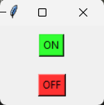
Application created on Python
Experiments designed:
Two experiments were designed to use this wave flume. The first was a study of clustering of regular floating objects. Those types of studies are generally focusing on how influence waves regimen and parameters of floating objects, like shape, size or density, on the clustering effects. These findings are crucial for understanding marine litter transport and its environmental implications. Some examples of this studies are:
- Barotta, J. W., Thomson, S. J., Alventosa, L. F. L., Lewis, M. & Harris, D. M. (2023, 28 April). Bidirectional wave-propelled capillary spinners. Communications physics, 6(87), 1-8.
- Gutiérrez, P. & Aumaître, S. (2016, November-December). Clustering of floaters of the free surface of a turbulent flow: An experimental study. European Journal of Mechanics - B/Fluids, 60(6), 24-32.
- Huang, G., Wing-Keung, A. L. & Huang, Z. (2011, March). Wave-induced drift of small floating objects in regular waves. Ocean Engineering, 38(4), 712-718.
- Sozza, A., De Lillo, F., Musacchio, S. & Boffetta, G. (2016, 6 September). Physical Review Fluids, 1(052401), 1-8.
The objects used on this experiment were designed in FreeCAD and 3D printed as is showing on the fallowing image:
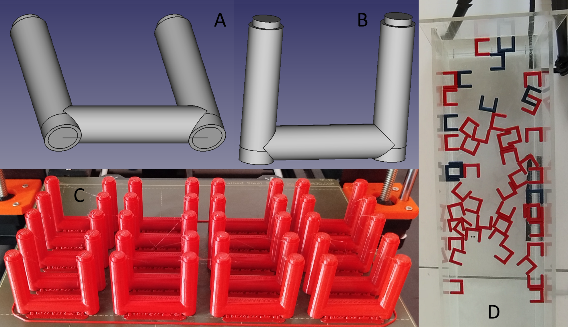
Floating objects used on the first experiment. A & B: Two different views of the design. C: Objects after 3D-printed process. D: Objects floating on the wave flume.
The second experiment consists in the test of the climbing of a marine buoy. The buoy used is a scale model of the Alex Manuel Rivera's Final Project. The models used on this experiment were molded and casted using Ecoflex™ 00-30 for the mold and Smooth-Cast™ 305 for the casting, as is showing on the fallowing image:
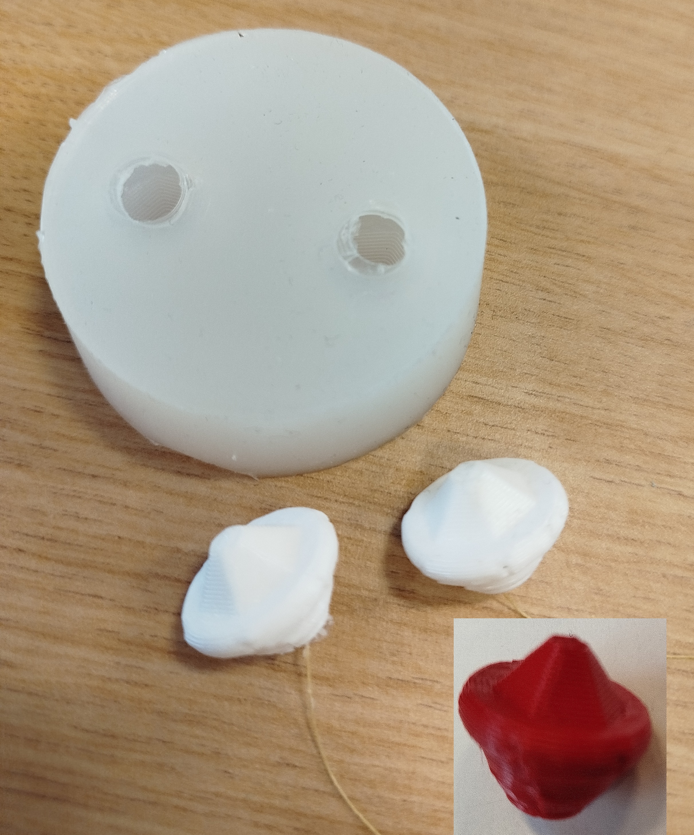
Objects obtained on the process of molding and casting.
Videos of the experiments.