12. Input Devices
In the context of electronics, input devices are those that facilitate the input of information or data into an electronic system. These devices are fundamental for interacting with computers, mobile phones, tablets, and other electronic devices. Some common examples of input devices include keyboards, mice, touchscreens, scanners, microphones, and cameras. Each of these devices serves a specific function by converting real-world information into data that the electronic system can process.
Research
The group assignment of this week you can found it here.
The main goal of this week is some input device to measure some magnitudes. In contrast to the majority of previous designs, I did not utilise any of the existing boards. Instead, I employed the Arduino Nano 33 BLE Sense Rev2, which has been specifically developed for the Internet of Things and TinyML. The rationale behind the construction of this microcontroller is that it is the one that I intend to utilise in my final project.
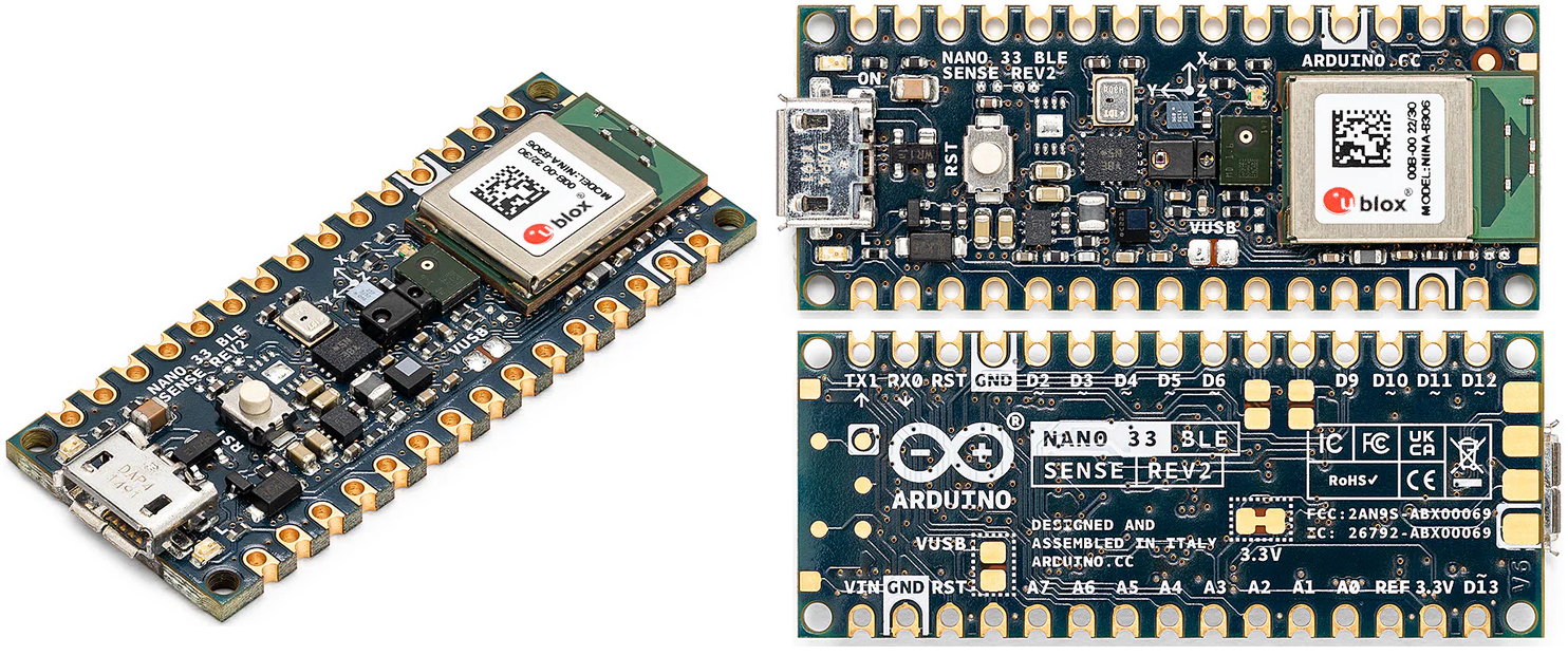
Image taken for https://store.arduino.cc/products/nano-33-ble-sense-rev2
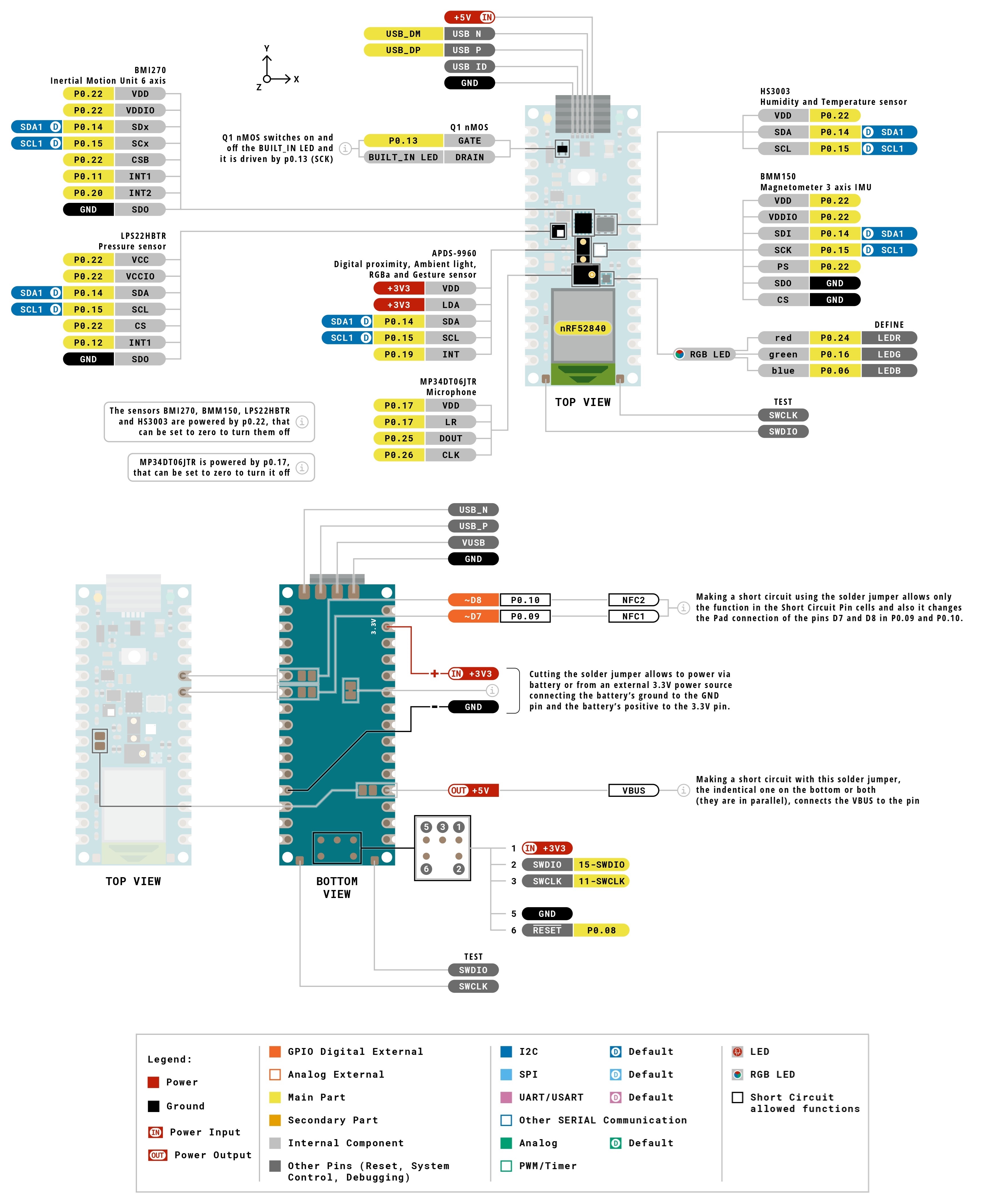
Image taken for Arduino Nano 33 BLE Sense Rev2 Pinout Docs
The aforementioned board is equipped with the following sensors:
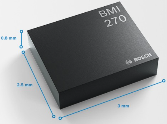
The device is an ultra-low power IMU optimized for wearable applications. It combines precise acceleration and angular rate measurement with intelligent on-chip motion-triggered interrupt features. The 6-axis sensor comprises a 16-bit triaxial gyroscope and a 16-bit triaxial accelerometer in a compact 2.5 x 3.0 x 0.8 mm3 LGA package.
This IMU is a member of the BMI260 family of inertial measurement units (IMUs), which are designed for fast and accurate inertial sensing in wearable applications. It incorporates Bosch's automotive-proven gyroscope technology with an improved accelerometer. Significant improvements include an extremely low zero-g offset and sensitivity error, low temperature drifts, robustness over PCB strain, and a low noise density.
This device incorporates a self-calibrating gyroscope that employs the motionless CRT (Component Re-Trimming) function to compensate for soldering deviations typical of MEMS devices. This technology ensures that post-soldering sensitivity errors are within ±0.4%. Furthermore, the device includes gesture, context, and activity recognition capabilities, as well as an integrated plug-and-play step counter/detector optimized for accurate step counting in wrist-worn devices. The IMU is well suited for integration into other types of wearable devices, including hearables, smart clothes, smart shoes, smart glasses, and ankle bands.
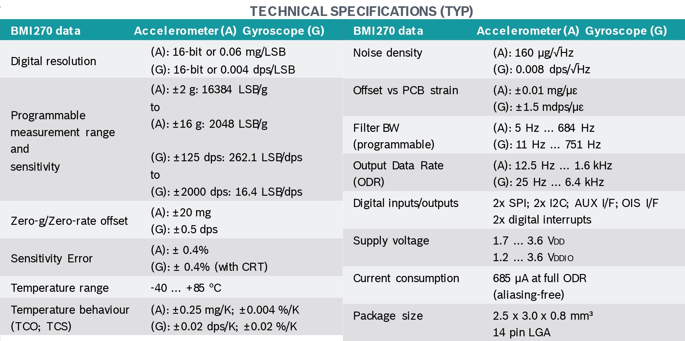
The BMI270 has been designed to provide optimal fit for modern embedded CE portable/audible devices. It offers a primary digital interface (I2C and SPI) and a freely configurable secondary digital interface (I2C and SPI).
The intelligent IMU has a wide range of VDD and VDDIO supply voltages, and performance and current consumption are stable over the entire supply range. Typical current consumption for the BMI270 accelerometer and gyroscope at full 6.4 kHz ODR is less than 700 μA. By enabling high output data rates with low current consumption, portable device manufacturers can circumvent the unpleasant aliasing effect, an effect that causes different signals to become indistinguishable when sampled at lower ODRs.
Further details regarding this sensor can be found in its accompanying datasheet.
The BMM150 is a geomagnetic sensor that measures the magnetic field in three perpendicular axes. It is based on Bosch's patented FlipCore technology, which enables it to adapt to the requirements of various three-axis mobile applications, such as electronic compasses, navigation, and augmented reality.
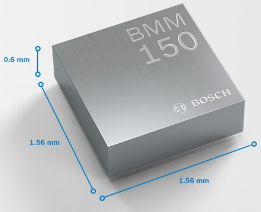
An evaluation circuit (ASIC) converts the sensor output into digital results that can be read out via industry-standard digital interfaces such as SPI and I2C. The package design and interfaces of the BMM150 allow it to meet a wide range of hardware requirements.
The sensor's ultra-compact size and flat profile render it particularly suitable for integration into mobile applications. Its wafer-level chip scale package (WLCSP) of only 1.56 x 1.56 x 0.6 mm³ affords it significant flexibility for placement on printed circuit boards.
The BMM150 operates at very low voltages, ranging from 1.62 V to 3.6 V for VDD and from 1.2 V to 3.6 V for VDDIO. Furthermore, it can be programmed to optimize its functionality, performance, and power consumption for specific applications.
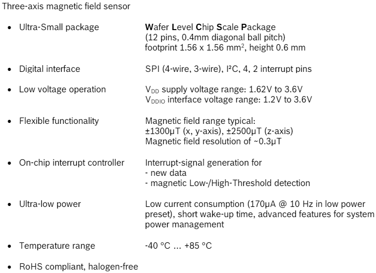
Image taken for https://docs.arduino.cc/resources/datasheets/bst-bmm150-ds001.pdf.
The device features a programmable interrupt engine, which provides developers with design flexibility. The sensor is capable of detecting all three axes of the earth's field, making it suitable for use in a range of applications, including cell phones, handheld devices, computer peripherals, human-machine interfaces, virtual reality applications, and game controllers.
Although the BMI270 and BMM150 sensors are separate on this board, they are typically integrated on a single chip. Consequently, when developing libraries for their management, they are treated as a single 9-axis IMU. This allows the use of multiple libraries that facilitate the use of this integrated 9-axis system. Examples of such libraries include the BMI270_BMM150 and LSM9DS1 libraries, which are capable of handling both the BMI270 and BMM150 sensors (as if they were one entity) as well as the LSM9DS1 sensor.
The following code provides a basic illustration of the values displayed on the screen (if the Monitor Serie is opened) for the magnitudes measured by the 9 axes:
  #include <Arduino_LSM9DS1.h>

    void setup() {
      Serial.begin(9600);
      while (!Serial);
      Serial.println("Started");

      if (!IMU.begin()) {
        Serial.println("Failed to initialize IMU!");
        while (1);
      }
      Serial.println("Magnetic Field in uT, Acceleration in g's, Gyroscope in degrees/second");
      Serial.println("Bx\tBy\tBz\tAx\tAy\tAz\tDx\tDy\tDz");
    }

    void loop() {
      float Bx, By, Bz, Ax, Ay, Az, Dx, Dy, Dz;

      if (IMU.magneticFieldAvailable()) {
        IMU.readMagneticField(Bx, By, Bz);
        IMU.readAcceleration(Ax, Ay, Az);
        IMU.readGyroscope(Dx, Dy, Dz);

        Serial.print(Bx);
        Serial.print('\t');
        Serial.print(By);
        Serial.print('\t');
        Serial.println(Bz);
        Serial.print('\t');
        Serial.print(Ax);
        Serial.print('\t');
        Serial.print(Ay);
        Serial.print('\t');
        Serial.println(Az);
        Serial.print('\t');
        Serial.print(Dx);
        Serial.print('\t');
        Serial.print(Dy);
        Serial.print('\t');
        Serial.println(Dz);
      }
    }
The LPS22HB is a highly accurate barometric pressure and temperature sensor manufactured by ST Microelectronics. This sensor is specifically designed for mobile and portable applications that require accurate pressure and temperature measurements. It has a pressure measurement range from 260 to 1260 hPa, with a resolution of 0.002 hPa. With regard to temperature, the LPS22HB is capable of measuring over a range of -40 °C to 85 °C, with a resolution of up to 0.01 °C. Typical sensor accuracy is ±0.1 hPa for pressure and ±0.5 °C for temperature, rendering it an optimal choice for applications requiring reliable measurements.
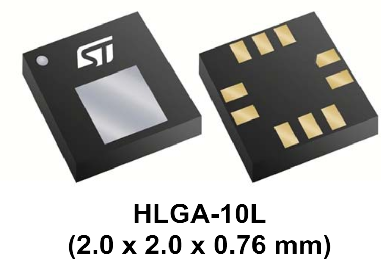
Image taken for the datasheet of the sensor.
One of the most notable attributes of the LPS22HB is its low power consumption, rendering it particularly well-suited for applications requiring battery power. Additionally, the sensor incorporates advanced functions such as free-fall detection, motion detection, and integrated temperature compensation, conferring upon it a comprehensive and versatile character. The LPS22HB's digital interface supports both I2C and SPI communication, facilitating seamless integration with microcontrollers, including those utilized on Arduino boards.
The LPS22HB sensor employs a physical principle called piezoresistivity to measure barometric pressure. It comprises a piezoresistive pressure element, which is a material whose electrical resistance varies as a function of applied pressure. When pressure is exerted on this element, its resistance changes, and this variation can be measured and converted into a pressure reading. Inside the LPS22HB sensor, the piezoresistive element is encapsulated in a sealed chamber. When the external pressure changes, this pressure is transmitted to the piezoresistive element through the chamber, causing a change in its resistance. An electronic circuit built into the sensor measures these resistance changes and converts them into a digital signal representing the pressure value. This digital signal can be read and processed by a microcontroller, such as those used on Arduino boards, via I2C or SPI interfaces.
Image taken for the https://docs.arduino.cc/tutorials/nano-33-ble-sense-rev2/barometric-sensor/.
The LPS22HB sensor also measures ambient temperature, employing a distinct physical principle from that used for pressure measurement. It incorporates a thermoelectric element, specifically a thermistor. A thermistor is a device whose electrical resistance varies as a function of the temperature to which it is exposed. Inside the LPS22HB sensor, the thermistor is embedded in the same sealed chamber as the piezoresistive element used to measure pressure. As the ambient temperature fluctuates, the thermistor detects these changes and modifies its electrical resistance in accordance. As with the pressure measurement, the LPS22HB's internal electronic circuitry is responsible for converting the thermistor's resistance alterations into a digital signal representing the temperature value. This digital signal can be read and processed by a microcontroller via the I2C or SPI interfaces.
This sensor can also be used to measure altitude indirectly. The relationship between atmospheric pressure and altitude is based on the barometric equation, also known as Laplace's formula. Because the LPS22HB sensor is able to measure pressure with high accuracy, it is possible to use this information to calculate the altitude at which the device is located.
The barometric formula relating pressure \(P\) and altitude \(h\) is as follows:
\[h = \frac{T_0}{L} \left[ \left( \frac{P}{P_0} \right)^{-\frac{g_0M}{RL}} - 1 \right]\]
where:
By providing the sensor with the measured pressure value \(P\), this formula can be applied and the corresponding altitude value \(h\) can be obtained. In this way, developers can easily obtain the altitude in their projects without having to implement the barometric equation themselves. This functionality is very useful in applications that require elevation knowledge, such as drones, portable weather stations or navigation systems.
To facilitate the management of this sensor, Arduino has developed an optimized low-power library that enables Arduino developers to integrate this sensor into their projects with minimal effort, freeing them from the burden of navigating the intricacies of device communication and configuration. This library is available in the form of Arduino_LPS22HB.h.
Further details regarding this sensor can be obtained from its accompanying datasheet.
The following code provides a basic illustration of the values displayed on the screen (if the Monitor Serie is opened) for the quantities measured by this sensor, including indirect altitude measurement:
  #include <Arduino_LPS22HB.h>

    void setup() {
      Serial.begin(9600);
      while (!Serial);

      if (!BARO.begin()) {
        Serial.println("Failed to initialize pressure sensor!");
        while (1);
      }
    }

    void loop() {
      // read the sensor value
      float pressure = BARO.readPressure();
      float altitudes = 44330 * ( 1 - pow(pressure/101.325, 1/5.255) );
      float temperature = BARO.readTemperature();
      // print the sensor value
      Serial.print("Pressure = ");
      Serial.print(pressure);
      Serial.println(" kPa");
      // print the sensor value
      Serial.print("Temperature = ");
      Serial.print(temperature);
      Serial.println(" C");
      // print the sensor value
      Serial.print("Altitude according to kPa is = ");
      Serial.print(altitudes);
      Serial.println(" m");
      // print an empty line
      Serial.println();
      // wait 1 second to print again
      delay(1000);
    }
The HS3003 sensor is a high-precision device designed to accurately measure relative humidity and temperature levels in a wide variety of applications. The HS3003 sensor was developed by TE Connectivity and is employed in a multitude of sectors, including HVAC and environmental control systems, as well as in home appliances and wearable devices.
One of the most notable features of the HS3003 is its measurement range. The sensor is capable of detecting relative humidity values ranging from 10% to 90% RH with an exceptional degree of accuracy, with a precision of ±1.5% RH. In terms of temperature, the sensor's range extends from -10 °C to 80 °C, with an equally notable precision of ±0.2 °C. These specifications render the sensor highly reliable and accurate, capable of providing accurate measurements in a wide range of environmental conditions.
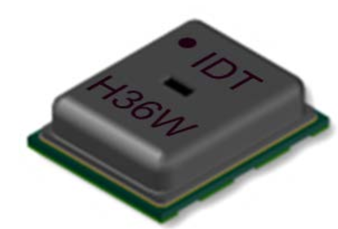
Image taken for the datasheet of the sensor.
Another noteworthy feature of the HS3003 is its I2C digital interface, which facilitates its integration into embedded systems and microcontrollers. This interface facilitates straightforward and efficient communication, thereby streamlining the design and implementation of systems that incorporate this sensor. Furthermore, the HS3003 is distinguished by its low power consumption, rendering it an optimal choice for applications that necessitate efficient battery use, such as portable or low-power devices.
Regarding its construction, the HS3003 is available in a small SMD (Surface Mount Device) format, facilitating its integration into printed circuit boards and compact devices. The HS3003's robust design and resistance to environmental factors such as humidity, corrosion, and shock make it a reliable and durable solution for a wide range of industrial and consumer applications.
A number of libraries have been developed for the purpose of managing this sensor. However, the official Arduino library, Arduino_HS300x.h, is particularly noteworthy.
The following code provides a basic illustration of the values displayed on the screen (if the Monitor Serie is opened) for the quantities measured by this sensor:
    #include <Arduino_HS300x.h>

    void setup() {
      Serial.begin(9600);
      while (!Serial);
      if (!HS300x.begin()) {
        Serial.println("Failed to initialize humidity temperature sensor!");
        while (1);
      }
    }

    void loop() {
      // read all the sensor values
      float temperature = HS300x.readTemperature();
      float humidity = HS300x.readHumidity();
      // print each of the sensor values
      Serial.print("Temperature = ");
      Serial.print(temperature);
      Serial.println(" °C");
      Serial.print("Humidity    = ");
      Serial.print(humidity);
      Serial.println(" %");
      // print an empty line
      Serial.println();
      // wait 1 second to print again
      delay(1000);
    }
The APDS-9960 sensor represents a significant advance in sensor technology, combining multiple functionalities on a single compact chip. Manufactured by Broadcom (formerly Avago Technologies), this sensor integrates gesture, color, and proximity detection into a comprehensive, low-power solution. One of the main features of the APDS-9960 is its ability to detect gestures in four directions: up, down, left, and right. This allows users to interact with electronic devices through simple hand movements, obviating the need to physically touch the screen or controls. This functionality significantly improves the user experience, especially in mobile and remote control applications.
In addition to gesture detection, the APDS-9960 also incorporates proximity and RGB color sensors. The proximity sensor is capable of detecting objects at a distance of up to 20 centimeters, thereby enabling the activation of functions such as turning on screens or locking devices when the user approaches or moves away. In contrast, the RGB color sensor provides detailed information about the color composition of the environment, which can be utilized in adaptive lighting or color analysis applications.
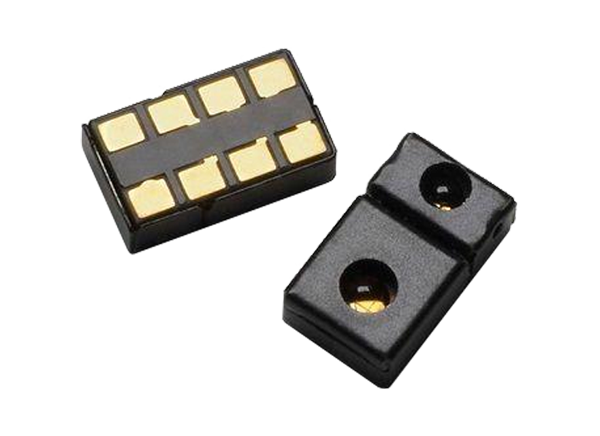
Image taken for the https://www.broadcom.com/products/optical-sensors/integrated-ambient-light-and-proximity-sensors/apds-9960.
One of the principal advantages of the APDS-9960 is its low power consumption, rendering it an optimal solution for portable and low-power devices. This sensor is capable of communicating via digital interfaces such as I2C or SPI, facilitating its integration into a diverse array of electronic systems. The APDS-9960 is a versatile and efficient sensor that offers multiple functionalities in a single component, rendering it an appealing option for the development of innovative and high-quality user interfaces.
For further insight into the specifications of this sensor, please consult the accompanying datasheet.
The Arduino_APDS9960.h library is used to manage this sensor. A compelling illustration of the utility of this library can be found in the following link.
The MP34DT06JTR sensor is a MEMS (Micro-Electro-Mechanical Systems) digital microphone manufactured by STMicroelectronics, a leading developer of sensor solutions. This device is distinguished by its ability to convert analog audio signals into a digital representation, rendering it an optimal choice for integration into a diverse array of applications that necessitate high-quality sound capture. One of the key features of the MP34DT06JTR is its wide frequency range, spanning from 20 Hz to 20 kHz. This frequency range coincides with the spectrum audible to the human ear, which means that the sensor is capable of capturing the full range of sounds that can be perceived by people. This feature is critical for applications such as audio recording, high-quality music playback, and speech recognition systems, where the fidelity of the audio signal is crucial.
In addition to its frequency range, the MP34DT06JTR is distinguished by its high sensitivity and low signal-to-noise ratio (SNR). The sensor's sensitivity is specified at -26 dBFS ± 3 dB, which indicates that it can capture audio signals at very low intensity levels without introducing an excessive amount of noise. Conversely, the signal-to-noise ratio of 62 dB ensures that the captured audio signal is well separated from the background noise, resulting in exceptional sound quality. These features render the MP34DT06JTR an optimal choice for applications that necessitate high-quality audio capture, such as video conferencing systems, home entertainment systems, and augmented and virtual reality solutions.
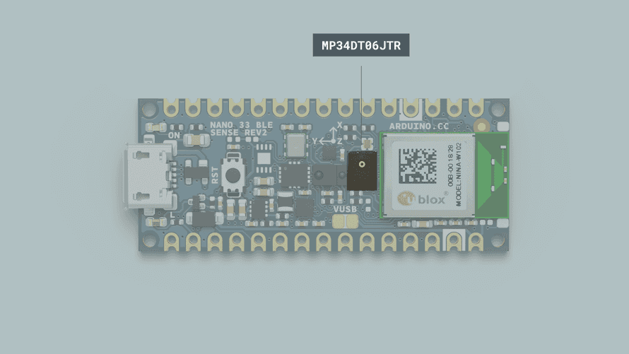
Image taken for the https://docs.arduino.cc/tutorials/nano-33-ble-sense-rev2/microphone-sensor/.
Finally, the MP34DT06JTR sensor boasts an important feature: its digital PDM (Pulse Density Modulation) interface. This interface enables the efficient transmission of digital audio signals using a single data wire, thus facilitating integration into embedded systems and digital signal processors (DSPs). Furthermore, the PDM interface offers increased resistance to electromagnetic noise, rendering it an attractive option for use in mobile and portable devices.
PDM (pulse density modulation) is a digital modulation technique that is commonly employed in MEMS microphone sensors, such as the MP34DT06JTR. This digital interface enables the efficient transmission of high-quality audio signals using a single data wire. In the PDM, the analog audio signal is converted into a sequence of digital pulses, where the density of these pulses represents the amplitude of the original signal. This is achieved by a process of pulse width modulation, where the duration of each individual pulse is adjusted proportionally to the amplitude of the audio signal.
The principal advantage of employing PDM in digital microphone sensors is that it facilitates straightforward and cost-effective integration in embedded systems and digital signal processors (DSPs). Since the audio data is transmitted as a sequence of pulses rather than as a complete analog signal, the volume of data to be processed is significantly reduced, resulting in lower power consumption and higher bandwidth efficiency.
Furthermore, the PDM interface is inherently robust to noise, rendering it an optimal choice for use in electromagnetically noisy environments. This makes it an attractive solution for mobile and portable applications that require high-quality audio capture.
The Arduino PDM.h library is employed in conjunction with digital microphones on Arduino development boards. The library offers a number of features, including the capacity to record audio using MEMS digital microphones, support for a range of audio formats, the ability to configure key parameters such as sample rate and resolution, real-time audio processing, including filtering and voice detection functions, and compatibility with a variety of Arduino boards, with support for digital microphones. This makes it a highly useful tool for developers seeking to integrate digital audio functionality into their Arduino applications.
The following code provides a basic illustration of the values displayed on the screen (if the Monitor Serie or Serial Plotter is opened) for the quantities measured by this sensor:
    #include <PDM.h>
    // buffer to read samples into, each sample is 16-bits
    short sampleBuffer[256];
    // number of samples read
    volatile int samplesRead;

    void setup() {
      Serial.begin(9600);
      while (!Serial);
      // configure the data receive callback
      PDM.onReceive(onPDMdata);
      // optionally set the gain, defaults to 20
      // PDM.setGain(30);
      // initialize PDM with:
      // - one channel (mono mode)
      // - a 16 kHz sample rate
      if (!PDM.begin(1, 16000)) {
        Serial.println("Failed to start PDM!");
        while (1);
      }
    }

    void loop() {
      // wait for samples to be read
      if (samplesRead) {
        // print samples to the serial monitor or plotter
        for (int i = 0; i < samplesRead; i++) {
          Serial.println(sampleBuffer[i]);
        }
        // clear the read count
        samplesRead = 0;
      }
    }

    void onPDMdata() {
      // query the number of bytes available
      int bytesAvailable = PDM.available();
      // read into the sample buffer
      PDM.read(sampleBuffer, bytesAvailable);
      // 16-bit, 2 bytes per sample
      samplesRead = bytesAvailable / 2;
    }
Example of use
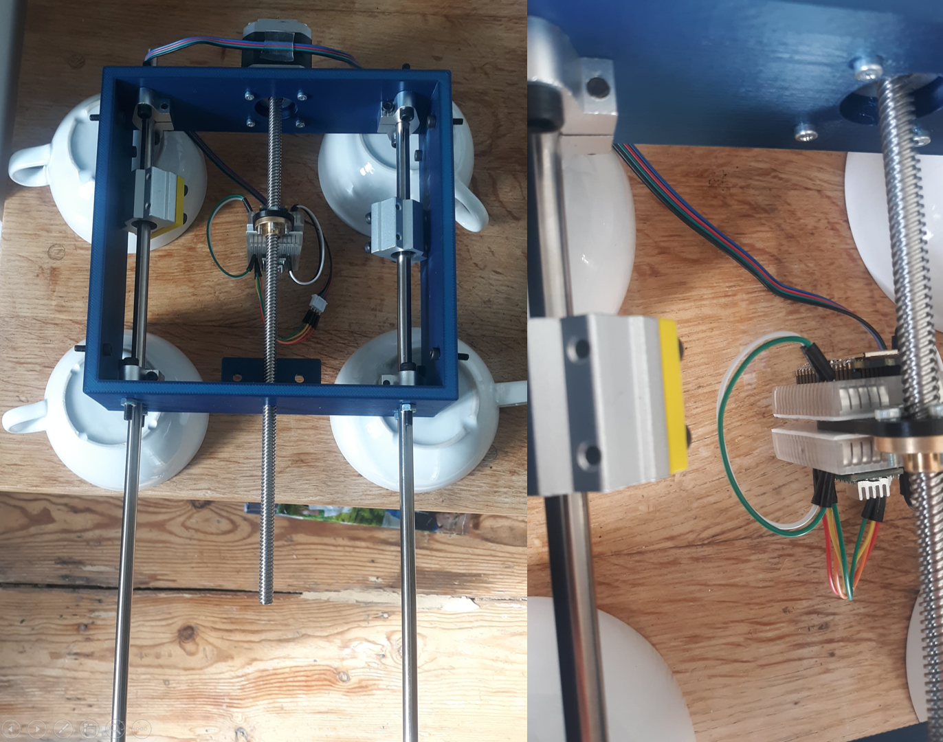
The initial phase of the project involved the design of the platform on which the wave generator will be situated. This was subsequently printed in 3D. The axes and worm of the stepper motor that will be used to move the piston-type paddle were aligned on the printed platform, as illustrated in the figures.
In order to fulfill the weekly individual assignment, I conducted tests on the operation of some of the sensors integrated in the Arduino Nano 33 BLE Sense board. I focused on the pressure, temperature, and IMU acceleration measurements. For this, I began with two examples from the Arduino_LPS22HB and Arduino_LSM9DS1 libraries, which I integrated into a single sketch, as shown below.
          #include <Arduino_LSM9DS1.h>
          #include <Arduino_LPS22HB.h>

          void setup() {
            Serial.begin(9600);
            while (!Serial);
            Serial.println("Started");

            if (!IMU.begin()) {
              Serial.println("Failed to initialize IMU!");
              while (1);
            }
            if (!BARO.begin()) {
              Serial.println("Failed to initialize pressure sensor!");
              while (1);
            }

            Serial.print("Accelerometer sample rate = ");
            Serial.print(IMU.accelerationSampleRate());
            Serial.println(" Hz");
            Serial.println();
            Serial.println("Acceleration in g's");
            Serial.println("X\tY\tZ");
          }

          void loop() {
            float x, y, z;

            if (IMU.accelerationAvailable()) {
              IMU.readAcceleration(x, y, z);

              Serial.print(x);
              Serial.print('\t');
              Serial.print(y);
              Serial.print('\t');
              Serial.println(z);
            }
            // read the sensor value
            float pressure = BARO.readPressure();

            // print the sensor value
            Serial.print("Pressure = ");
            Serial.print(pressure);
            Serial.println(" kPa");

            float temperature = BARO.readTemperature();

            // print the sensor value
            Serial.print("Temperature = ");
            Serial.print(temperature);
            Serial.println(" C");

            // print an empty line
            Serial.println();

            // wait 1 second to print again
            delay(100);
          }
As can be observed, the operation of the sensors is accurate and in accordance with the intended functionality.
Test of the Arduino Nano 33 BLE Sense
Making a board with extra sensors
After explore the sensors of the Arduino Nano 33 BLE Sense Rev2 I decided add more sensors to a board making a new one, with the Xiao Seed Studio microcontroller. Appling the knowledge of the week 8 I designed the following board on KiCAD.
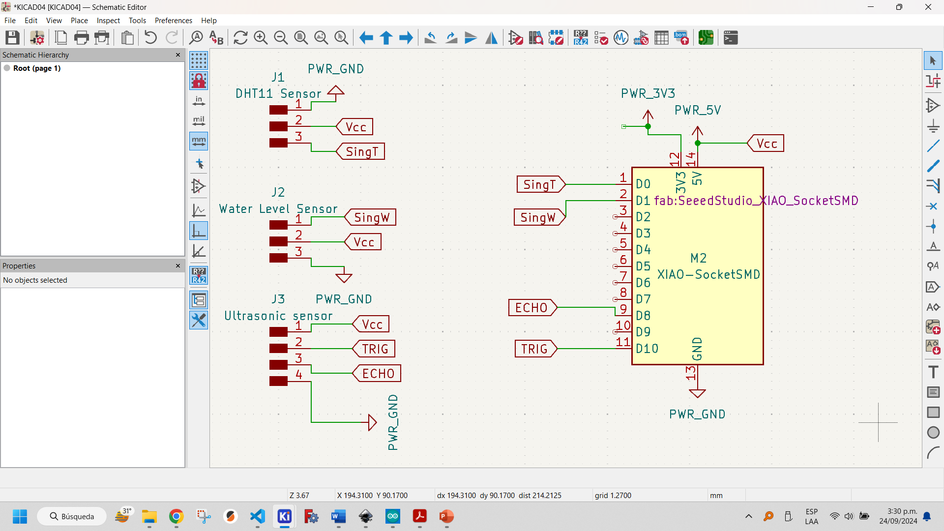
Schematic for extra sensors board on KiCAD
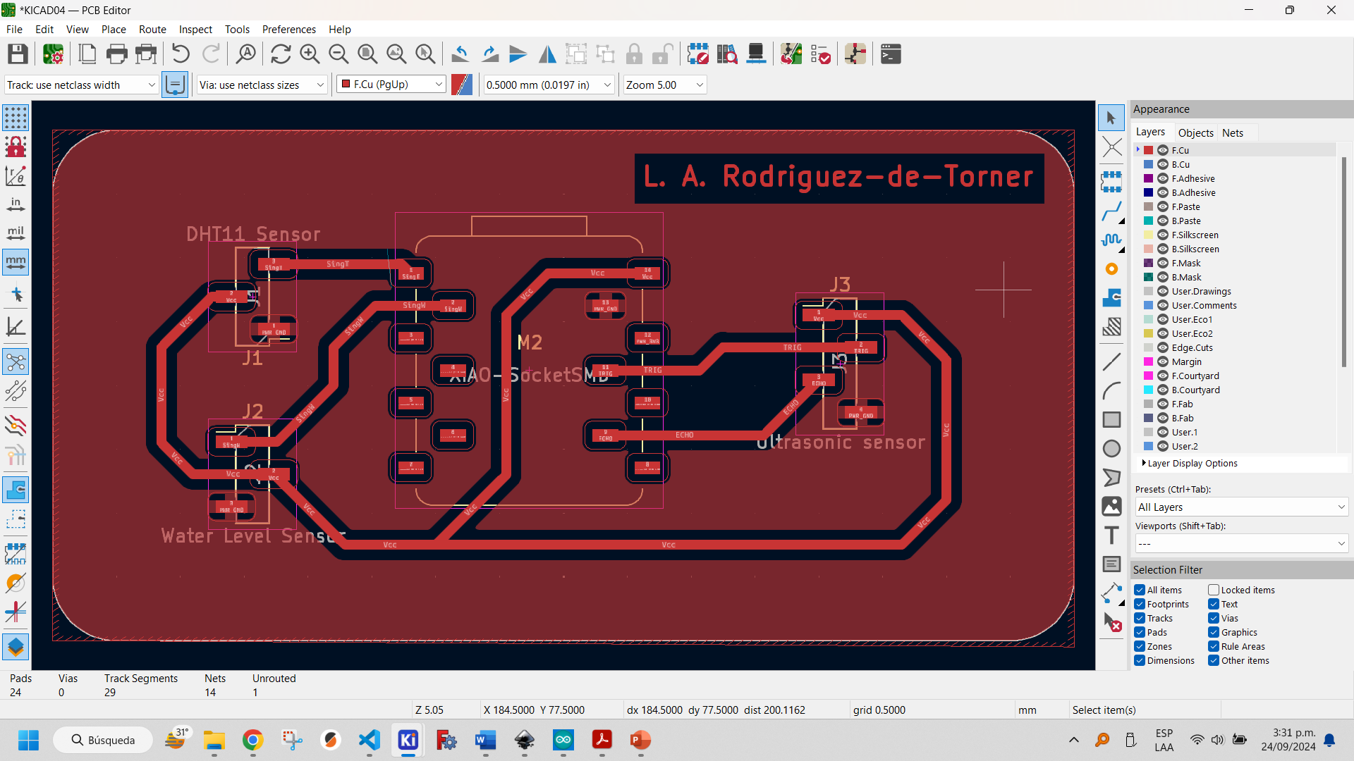
PCB for extra sensors board on KiCAD
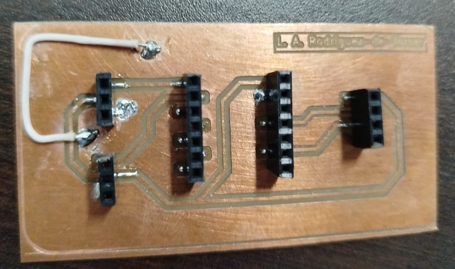
Board with soldered header. The white wire is used to connect the two isolated ground areas to each other.
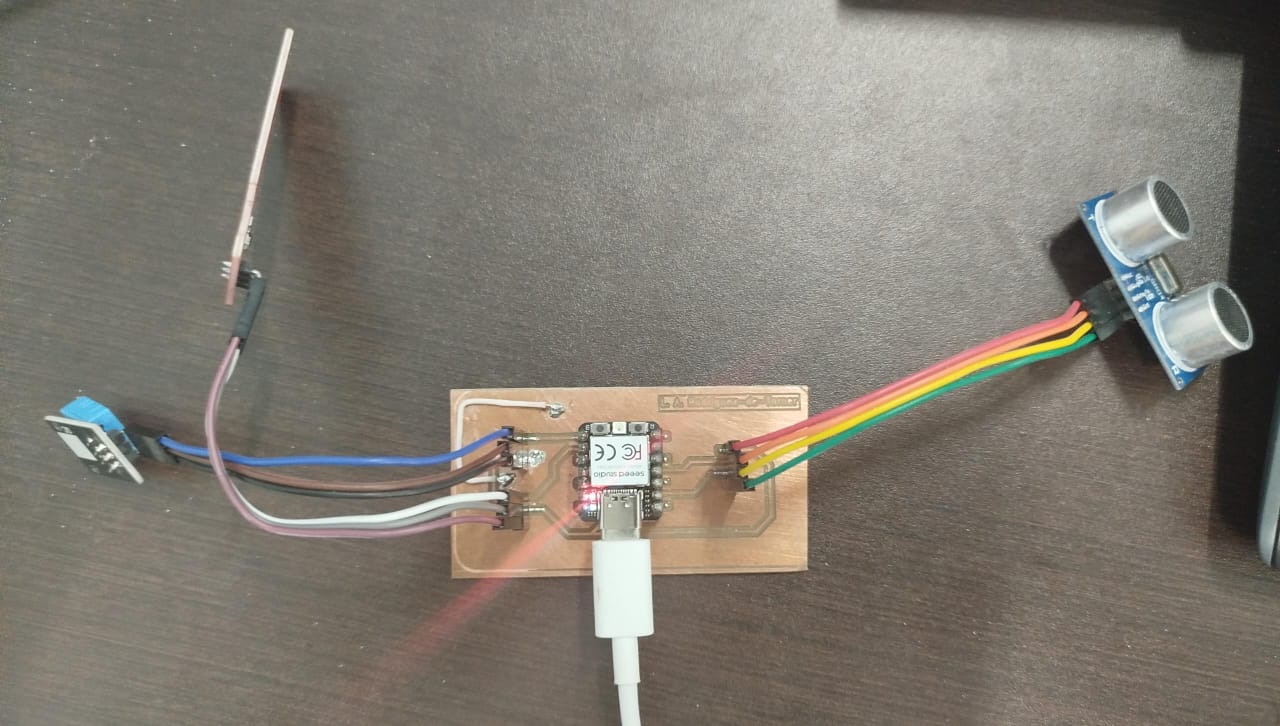
Board with sensors added.
You can download the design files for this board here.
Exploring the add sensors
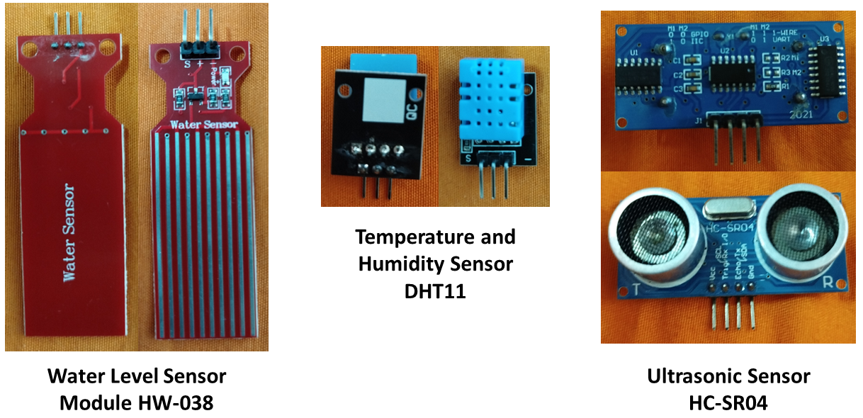
Added sensors
The DHT11 is classify as an environmental sensor because is used typically for environmental projects. This sensor is capable to measure temperature, in a range to 0 °C to 50 °C with a precision of to 1 °C , and humidity, in a range to 20% to 80% with a precision of 1%. This sensor has a ratio of frequency of 1 s. More information about this sensor can be found on its datasheet.
To use this sensor is common employ the library DHT11.h. The fallowing code show a simple example of how to use it to read temperature and humidity, modifying an example of this library.
            #include <DHT11.h> // Include the DHT11 library for interfacing with the sensor.
            DHT11 dht11(26);         // According the board design, the sensor is connected to pin D0 (number 26)

            void setup() {
              Serial.begin(9600);    // Using a baud rate of 9600 bps.
              dht11.setDelay(2000);  // 2-second delay to avoid data overwrite.
            }

            void loop() {
                int temperature = 0; // Initiation of the variable for the temperature
                int humidity = 0;    // Initiation of the variable for the humidity

                // Attempt to read the temperature and humidity values from the DHT11 sensor.
                int result = dht11.readTemperatureHumidity(temperature, humidity);

                // Check errors and print the values
                if (result == 0) {
                    Serial.print("Temperature: ");
                    Serial.print(temperature);
                    Serial.print(" °C\tHumidity: ");
                    Serial.print(humidity);
                    Serial.println(" %");
                } else {
                    // Print error message based on the error code.
                    Serial.println(DHT11::getErrorString(result));
                }
            }
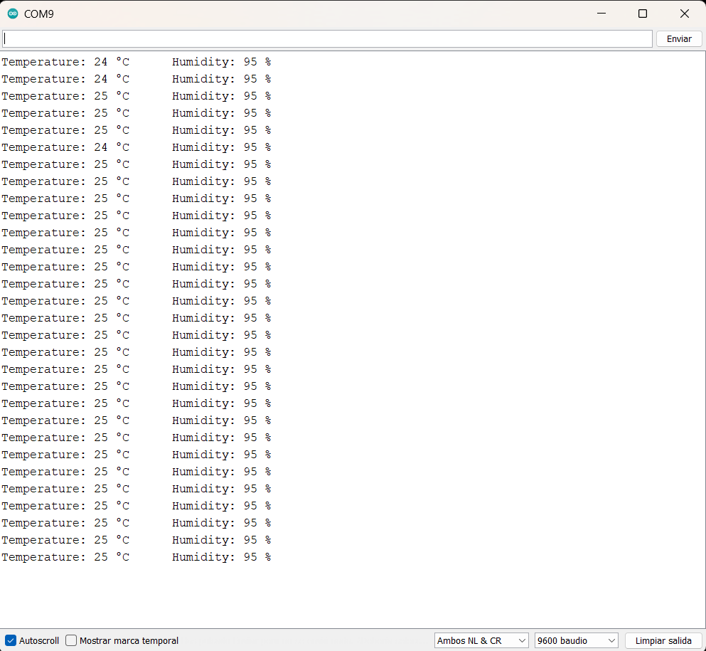
Monitor Serial showing DHT11 sensor readings of temperature and humidity.
Video measuring temperature and humidity
The Water Level Sensor Module HW-038 is an analogic sensor. It has ten exposed copper traces, five of which are power traces and the others five are sense traces. These traces are interlaced so that there is one sense trace between every two power traces. Normally, power and sense traces are not connected, but when immersed in water, they are bridged. The more water the sensor is immersed in, the better the conductivity and the lower the resistance. The less water the sensor is immersed in, the poorer the conductivity and the higher the resistance. The sensor generates an output voltage proportional to the resistance linearly; by measuring this voltage, the water level can be determined. More information about this sensor can be found on the following links:
- https://lastminuteengineers.com/water-level-sensor-arduino-tutorial/
- https://curtocircuito.com.br/datasheet/sensor/nivel_de_agua_analogico.pdf?srsltid=AfmBOorOfPaNrXMIMmtC_i6EJpse5_nksw1F1sHQthr2hPq8Hxmwfm5a
- https://www.bitmi.ro/domains/bitmi.ro/files/files/bitmi-datasheet-senzor-nivel-masurare-apa-1794.pdf
Water Level Sensor Working. Animation taken from https://lastminuteengineers.com/water-level-sensor-arduino-tutorial/
The fallowing code show how to use this sensor:
            #define SensorPin A1 // According the board design, the sensor is connected to pin A1
            int level = 0;       // Value for storing water level

            void setup() {
             Serial.begin(9600); // Using a baud rate of 9600 bps.
            }

            void loop() {
              level = analogRead(SensorPin); // Read the analog value from the sensor
              Serial.print("Water level: "); // Print the value for Monitor Serie
              Serial.println(level);         // Print the value for Monitor Serie
              delay(300);                    // Delay for 300 ms
            }
Video measuring water level
The Ultrasonic Sensor HC-SR04 is usually used to measure distance. It counts with 2 piezoelectric plates with a frequency of vibration of 40 kHz (ubicated on the ultrasound part of the audible spectrum). They name Trigger, the and Echo
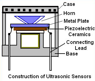
It all begins when the Trigger pin is set to HIGH for 10 µs. The sensor then sends out an ultrasonic burst of eight pulses at 40 kHz in response. The eight-pulse pattern is designed in a way that helps the receiver distinguish the transmitted pulses from ambient ultrasonic noise. The eight ultrasonic pulses then travel through the air away from the transmitter. Meanwhile, the echo pin goes high to start the echo signal. If the pulses aren't reflected, the echo signal times out and drops after 38 ms. So, a 38 ms pulse means there's no obstruction in the sensor's range. If the pulses are reflected, the echo pin goes low as soon as the signal is received. This generates a pulse on the echo pin whose width varies from 150 µs to 25 ms, depending on how long it takes to receive the signal.
Echo Working when no Obstacle in front.
Echo working when Obstacle in front.
Ultrasonic Sensor Working. Animations taken from https://cursos.mcielectronics.cl/2022/12/06/como-funciona-el-sensor-ultrasonico-hc-sr04-y-como-se-conecta-con-arduino/
More information about this sensor can be found here
The sensor returns the time elapsed between the trigger emission event and the echo reception event, given in microseconds. This is why the software must be used to calculate the distance. This can be done in two closely related ways. The first is to assume a constant temperature, which means that the speed of sound in air is constant. For a temperature of 25 °C, the speed of sound would be approximately 348 m/s. The second way is to consider that air can be approximated to an ideal gas, so that the speed of sound depends on temperature according to the following expression:
\( v = \sqrt{\frac{\gamma R T}{M}} \)
Where \(v\) is the speed of sound in the gas, \(\gamma\) is the ratio of the heat capacity at constant pressure to the heat capacity at constant volume (\(\gamma = 1.40\) for the air), \(T\) is the thermodynamic temperature (\(T = 298 \, \text{K}\) in this case), \(R\) is the universal gas constant (\(R = 8.31 \, \text{J/mol K}\)) and \(M\) is the molar mass of the gas (\(M = 2.88 \times 10^{-2} \, \text{kg/mol}\) for the air).
For most applications it is sufficient to consider the speed of sound constant. The following code determines the distance, in centimeters, taking into account that the speed of sound is equal to 348 m/s.
            #define EchoPin 2
            #define TriggerPin 3
            void setup() {
              Serial.begin(9600);
              pinMode(TriggerPin, OUTPUT);
              pinMode(EchoPin, INPUT);
            }

            void loop() {
              int discm = PING(TriggerPin, EchoPin);
              Serial.print("Distance: ");
              Serial.print(discm);
              Serial.println("cm");
              delay(500);
            }

            int PING(int TriggerPin, int EchoPin) {
              long Time, Dist;
              digitalWrite(TriggerPin, LOW);
              delayMicroseconds(4);
              digitalWrite(TriggerPin, HIGH);
              delayMicroseconds(10);
              digitalWrite(TriggerPin, LOW);
              Time = pulseIn(EchoPin, HIGH);
              Dist = Time * 87/5000;
              return Dist;
            }
Video measuring distance