My Final Project GIOXANCE
As you may have already read the "About me" section, I study Biomedical Engineering, so the main idea of my final project is to design a device that helps people who have a visual disability (total blindness), which usually goes unnoticed and many times other people treat them badly.
Brief Research
The Mexican Society of Ophthalmology estimates that in Mexico there are 2,237,000 people with visual impairment and nearly 416,000 people with blindness, which places our country among the 20 with the highest number of people affected by visual impairment or blindness. In the country, 25 out of every 100 disabled people were victims of discrimination at least once a year, this group has the highest prevalence of all those considered.
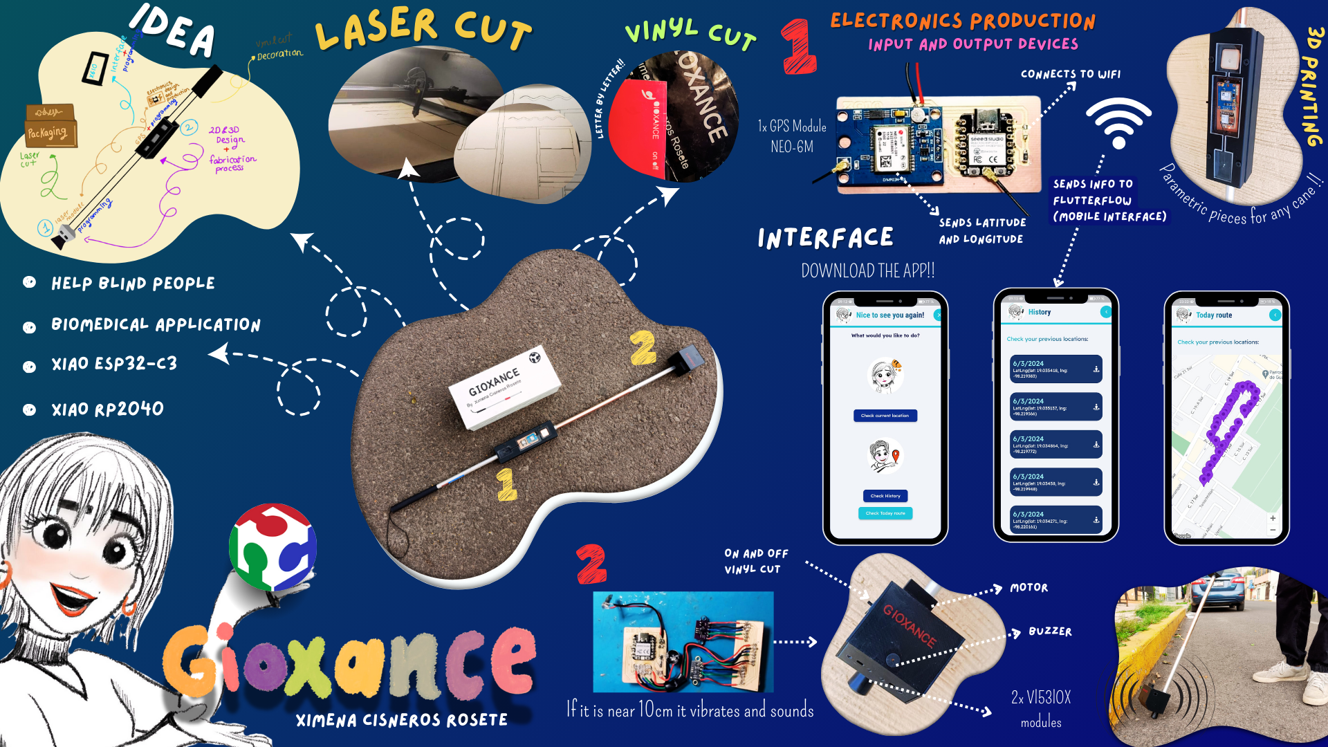
The idea is based on making a cane which has two main parts:
-
The first part would be to use an ultrasonic sensor that can detect any kind of obstacle in front of the person, so it can immediately make a vibration in their hand and also make a sound.People who are blind often experience a remarkable enhancement in their other senses. Some individuals develop a heightened sense of touch, allowing them to perceive vibrations with extraordinary sensitivity, while others find their sense of hearing becomes exceptionally acute. Because of these adaptations, a cane for the blind incorporates features for both senses, enabling users to navigate their surroundings through tactile feedback and auditory signals.
-
The second part is to implement a type of GPS in the same cane which will have a connection internet and it would tell the person their exact position or location. The second part arose from talking to a person with this disability, where she told me that there are applications that can give the exact location at anytime she would like to; however, this means that she has to carry her cell phone in her hand, causing her some insecurity about whether they can steal it. She commented that if the same purpose of the aplication was on the cane, it would be much more useful. However, the interface is not directly for the person who is blind. During an interview with a blind individual and their sister, it became clear that the sister constantly worried about whether her sibling would successfully catch the bus or get lost. Therefore, the interface is primarily designed for these concerned loved ones. It allows them to easily check that their family member has reached their destination, providing peace of mind from the comfort of their home.
This system is not an invasion of privacy because it operates with the consent and cooperation of the blind individual. It is designed to enhance their independence and safety by reducing the constant worry of their loved ones. This way, the blind person can navigate more freely, knowing that their family has a non-intrusive means to ensure their well-being. Additionally, this support system can foster a greater sense of independence for the blind individual, as it alleviates the need for constant check-ins or physical accompaniment.
Who has done what beforehand?
Additionally, I was inspired by a TikTok video that demonstrated using an ultrasonic sensor to trigger a buzzer when detecting an obstacle. However, as you can see, the setup in the video involves exposed wires and lacks sophistication. I aim to refine this concept, incorporating a more polished design and integrating it seamlessly with the GPS functionality to provide a comprehensive solution for visually impaired individuals.
TikTok video : Ultrasonic sensor for a cane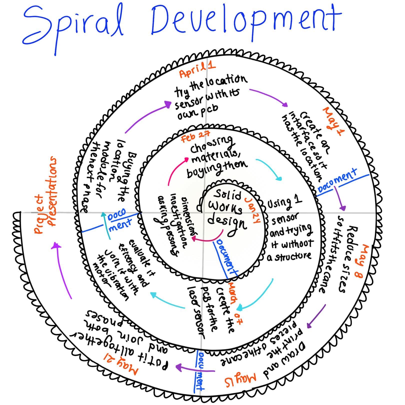
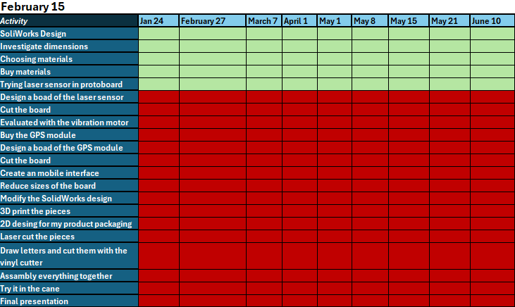
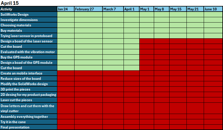
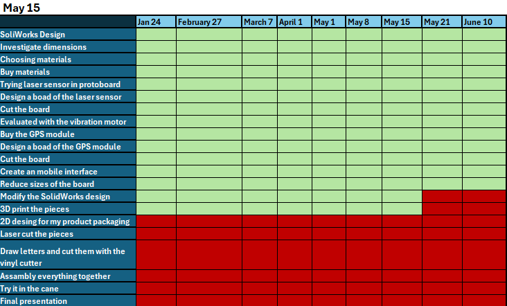
The spiral development approach, a software development methodology, worked wonderfully for me because it allowed me to set small, achievable goals that ultimately led to the final result. This approach involves iterative cycles, each consisting of planning, risk analysis, engineering, and evaluation phases. By following this methodology consistently, I was able to stay on track and meet all deadlines. Each iteration of the process helped me to refine and improve my work, ensuring a high-quality outcome. This structured yet flexible approach was instrumental in guiding my project to success
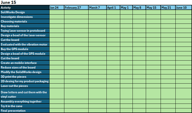
I decided to create calendars for every two months on the 15th to show my progress on the project. In the end, I separated May and June to display the specific progress for those months since they were 100% focused on the tasks being done.
-
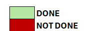
What tasks have been completed?
At the moment everything is already complete, ¡YAY!
-
What tasks remain?
None :)
-
What has worked? what hasn't?
Everything worked as I planned!
-
What questions need to be resolved?
I want to continue developing the project, and I have just one question: What is the next step? To provide some context, my plan is to integrate an advanced AI system capable of delivering precise location information through headphones. The AI will guide users by audibly informing them of their exact location, enhancing navigation and orientation in various environments. This feature could significantly benefit visually impaired individuals, improve navigational tools, and offer detailed location-based information in complex areas. Given this objective, what should be the next step in our development process to achieve this functionality?
-
What will happen when?
I will continue developing the project and plan to integrate an advanced AI system. This system will be designed to deliver precise location information audibly through headphones. The goal is to create a seamless and intuitive user experience, where the AI can guide users by telling them exactly where they are, ensuring accurate and helpful navigation or orientation in various environments. This functionality could be especially useful for applications such as assisting visually impaired individuals, enhancing navigational tools, or providing detailed location-based information in large or complex areas.
-
What have you learned?
I have learned a great deal this week, successfully integrating everything we covered into my final project. This accomplishment has left me feeling very proud of myself. By applying each concept and technique we studied, I was able to create a cohesive and functional end product. Additionally, I believe that the individualized learning approach significantly enhanced my cognitive performance compared to other times. This tailored method allowed me to focus deeply on the material, understand it thoroughly, and apply it effectively, leading to a more rewarding and enriching learning experience.
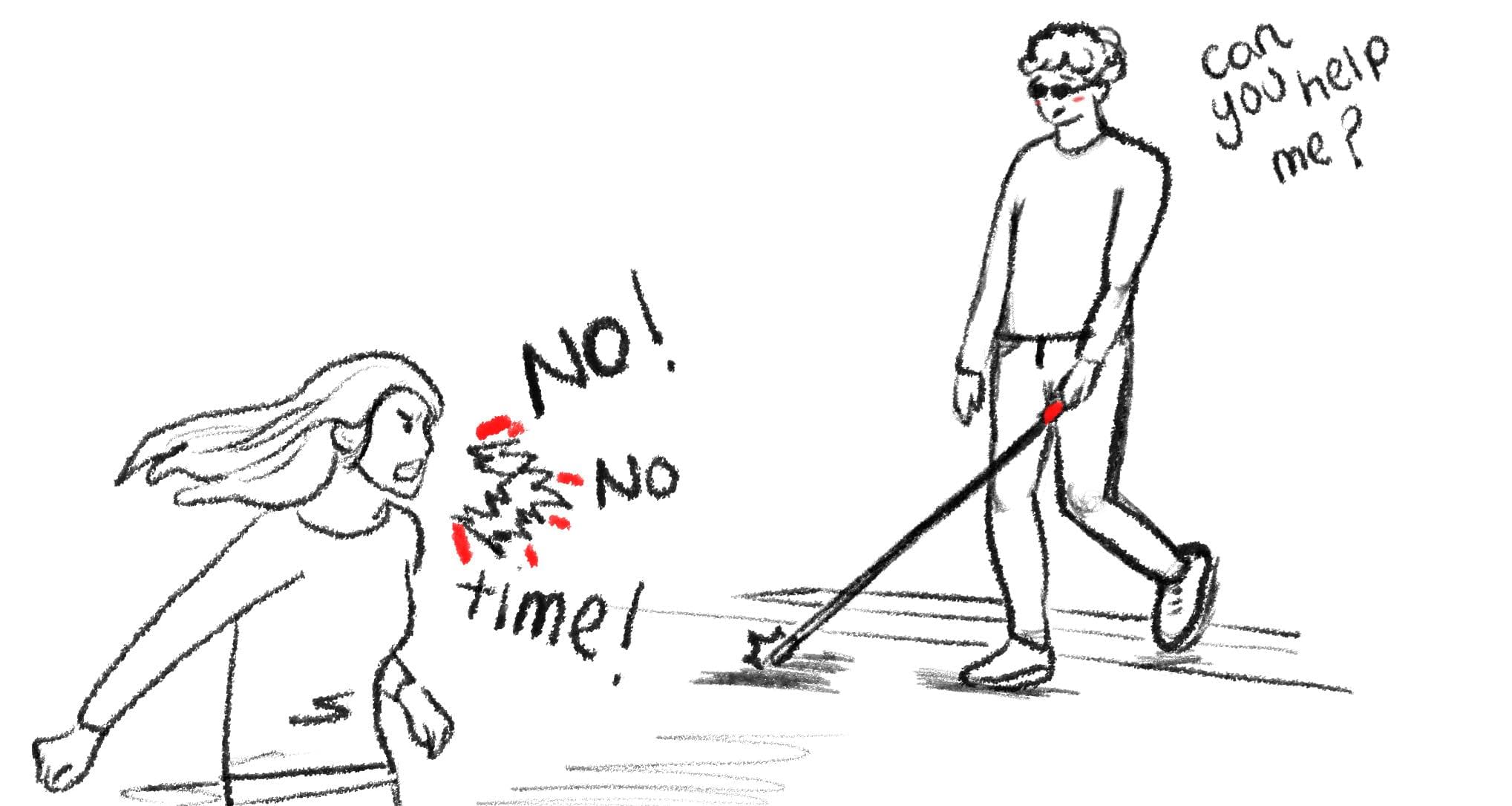
This drawing represents the fact that most times persons that have a visual disability, They have the problem that they cannot calmly ask people on the street if there is an obstacle in front of them or if they are on the right street, because they often rudely answer that they don't have time or not to bother them.
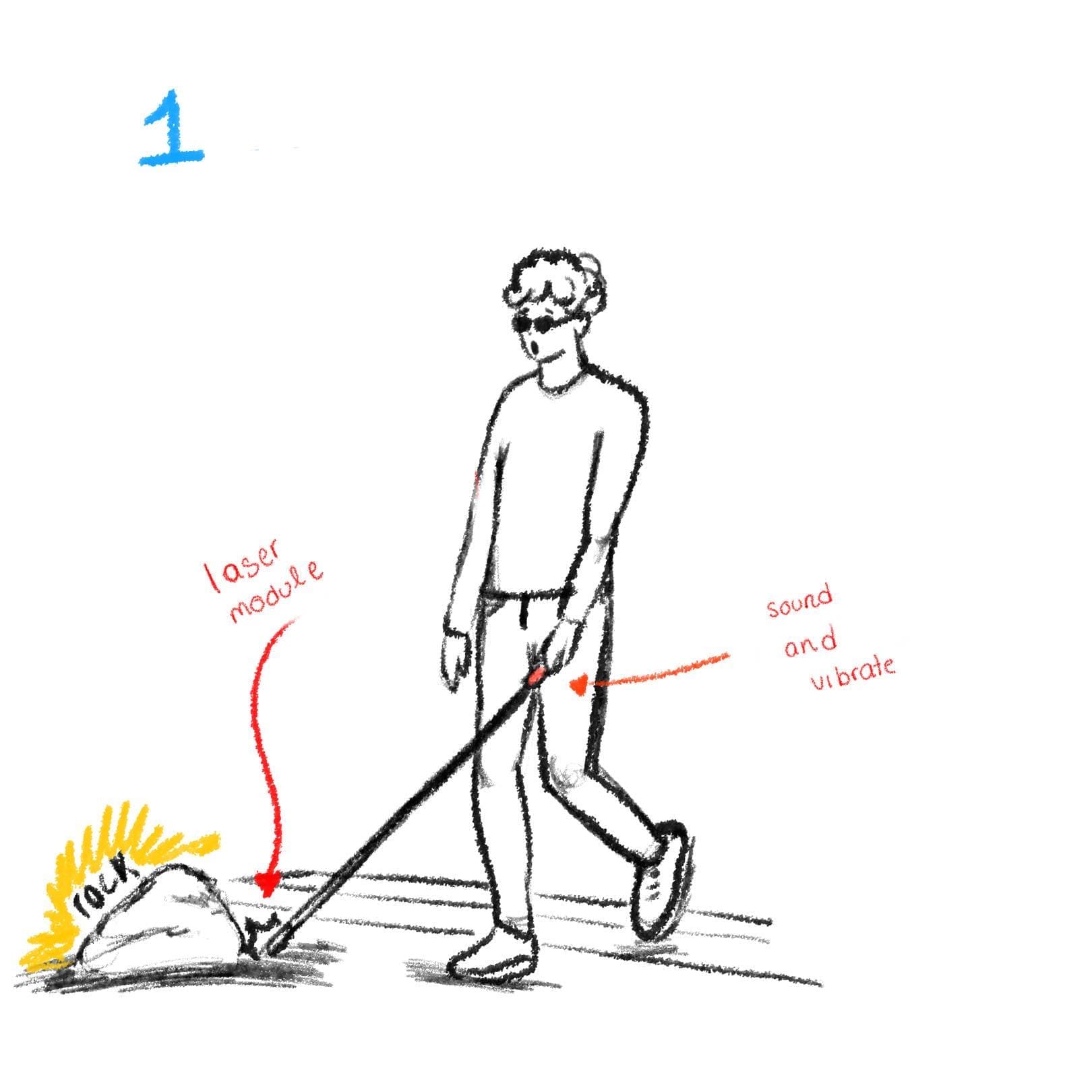
Here is the visual represetation of the point number 1 explained before.
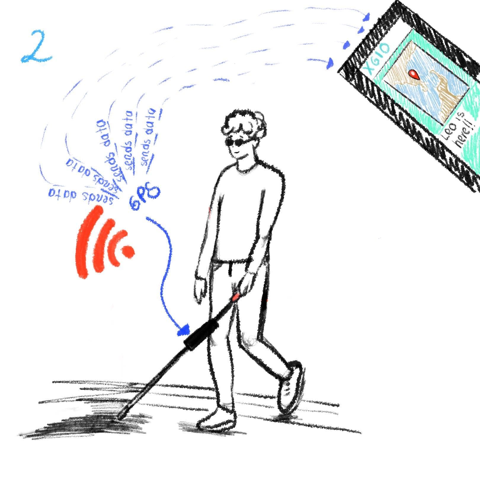
Here is the visual represetation of the point number 2 explained before.
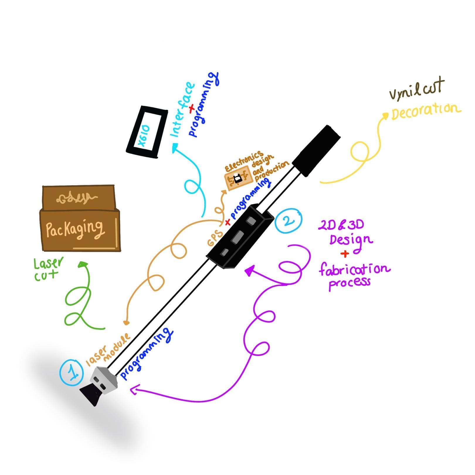
Here is the sketch of the cane were it has both numbers of the points explained before.
What materials and components will be used?, where will they come from? and how much will they cost?
| Qty | Description | Price | Link/where will they come from |
|---|---|---|---|
| 1 | XIAO RP2040 | $9 USD | Amazon link of the XIAO RP2040 |
| 1 | XIAO ESP32-C3 | $9 USD | Amazon link of the XIAO ESP32-C3 |
| 2 | GY-VL53L0XV2 | $7.55 USD | Amazon link of the module VL53L0X |
| 1 | Ublox Neo-6m Gps Module | $7 USD | Mercado libre link of the GPS sensor |
| 1 | Vibrator motor | $12 USD (package of 10) | Amazon link of the vibrator motor |
| 1 | Passive buzzer | $1 USD | Steren link of the passove buzzer |
Note: also the pins, smd components and the cables.
I decided to divide all the process of both parts in my project, because each has a especific functioning and structure.
Development of the First Part
We recall the initial component as a sensor designed to detect objects and transmit vibrations to the handle of the cane. This feature serves to alert the user in case of potential obstacles, thereby enhancing safety and mobility.
The module that is going to be used is the Vl53l0x :
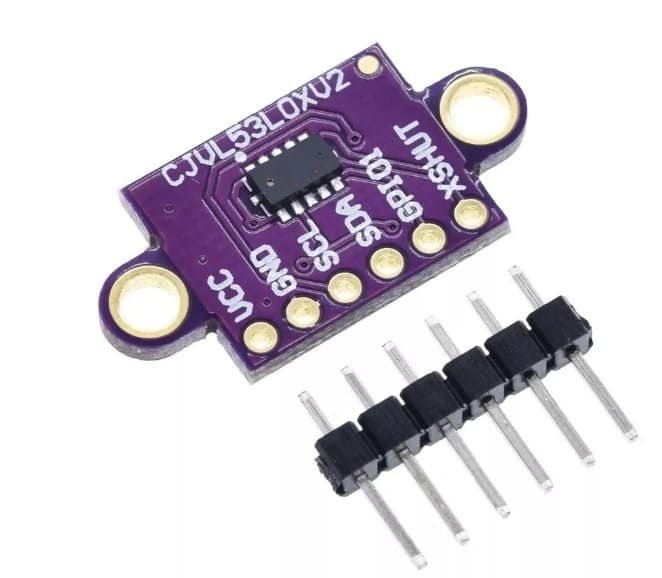
The VL53L0X is a compact, low-power time-of-flight sensor manufactured by STMicroelectronics. Using laser pulses, it accurately measures the distance between the sensor and a reflected object, making it ideal for applications where space is limited and precise distance detection is required. With an easy-to-use I2C interface and adjustable measurement range, the VL53L0X is widely used in electronics and robotics projects, as well as indoor navigation applications, motion-detecting toys, and more.
As you can see in the Week 11, there is my first attempt.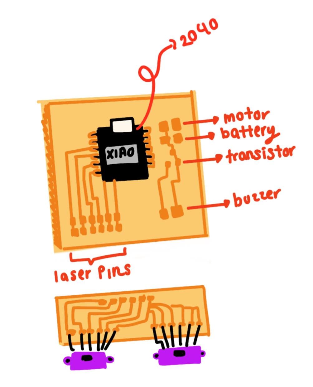
This was my initial drawing of what I wanted to do, this with the purpose of possibly moving everything around and colocate it as the way I wanted.
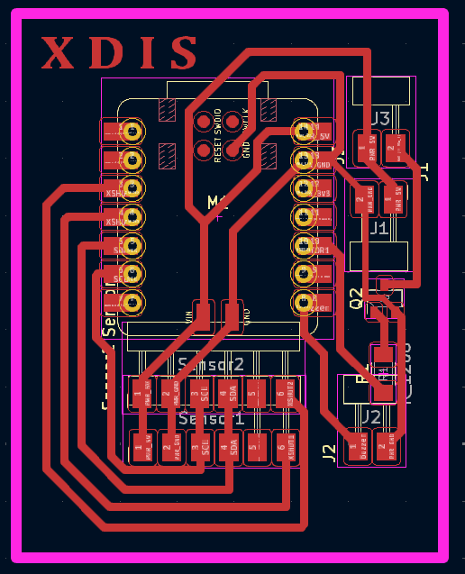
Here is the visual represetation of the point number 1 explained before.
Here is the visual represetation of the point number 2 explained before.
Here is the sketch of the cane were it has both numbers of the points explained before.
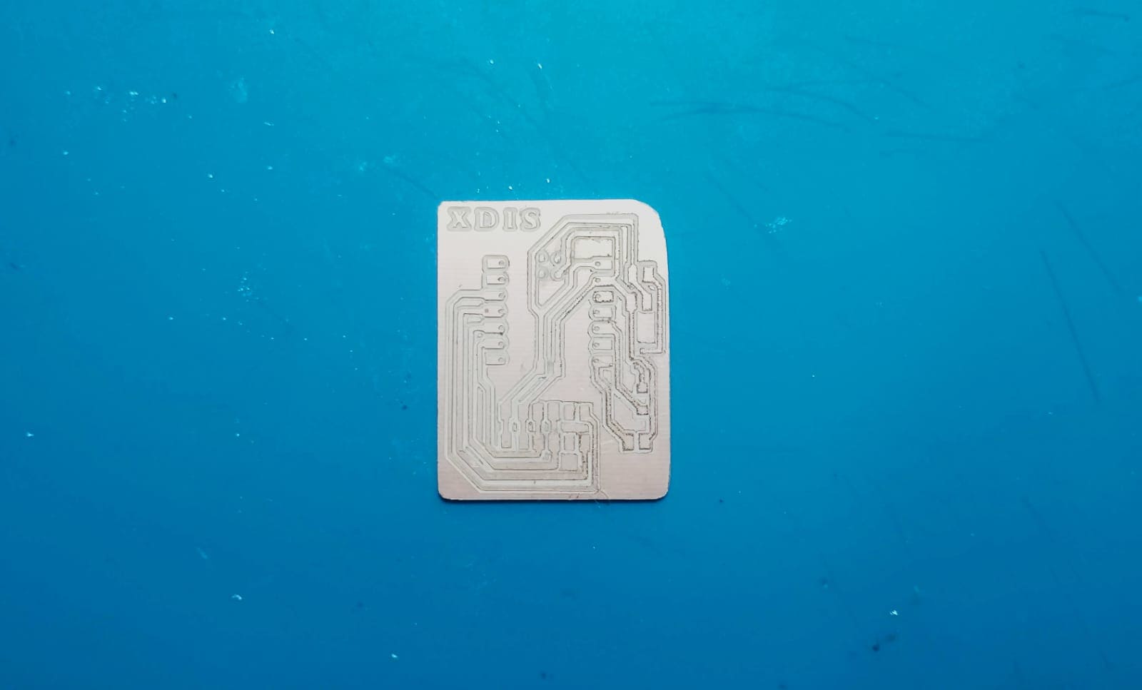
Here is a small clip of how I solded the pieces:
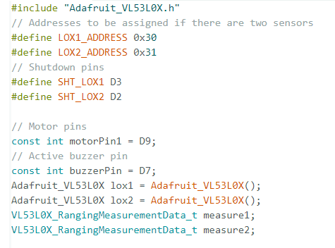
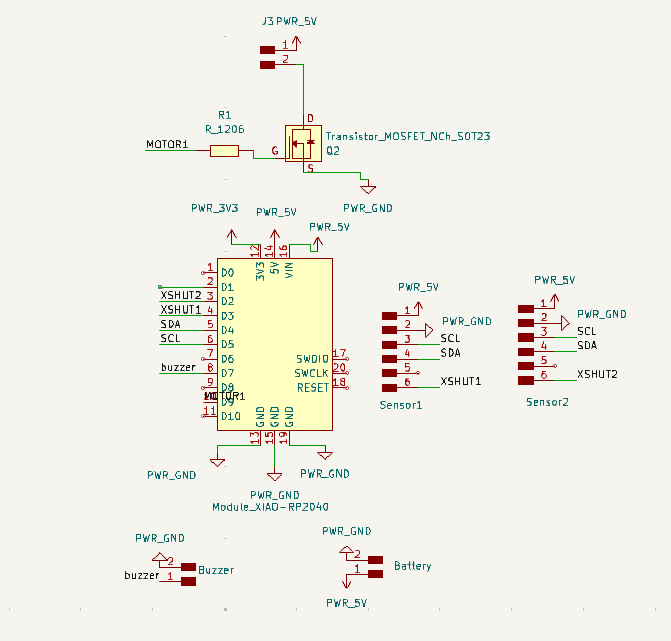
Certainly, here's an explanation of what the code does: This code interfaces with two Adafruit VL53L0X time-of-flight distance sensors, a motor, and a buzzer. The sensors are assigned specific I2C addresses (0x30 and 0x31) and connected to separate shutdown pins (D3 and D2) to control their power state. The motor and buzzer are connected to pins D9 and D7, respectively.
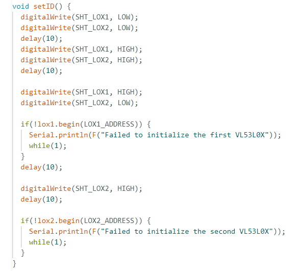
In the setup() function, the serial communication is initialized, and the pins for the sensors, motor, and buzzer are configured as outputs. The sensors are initially set to a low state to reset them, then they are powered up one by one in the setID() function. This function also initializes the sensors with their respective addresses.
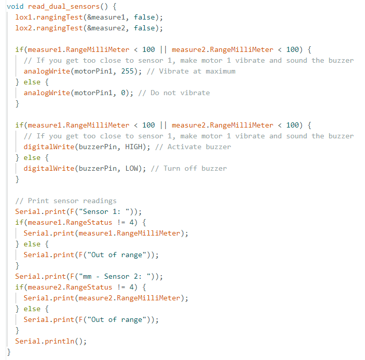
The loop() function repeatedly calls read_dual_sensors() which reads distance measurements from both sensors. If either sensor detects an object within 100 millimeters, the motor is activated to vibrate at maximum strength, and the buzzer is turned on.
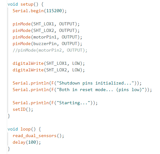
If no objects are detected within this range, both the motor and the buzzer are turned off. The distance readings from both sensors are printed to the serial monitor for debugging and verification purposes.
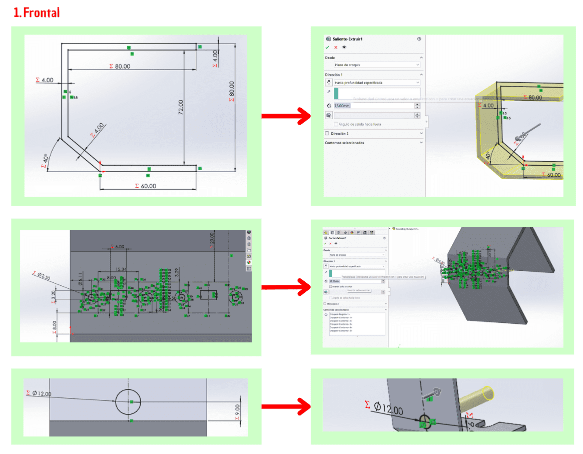
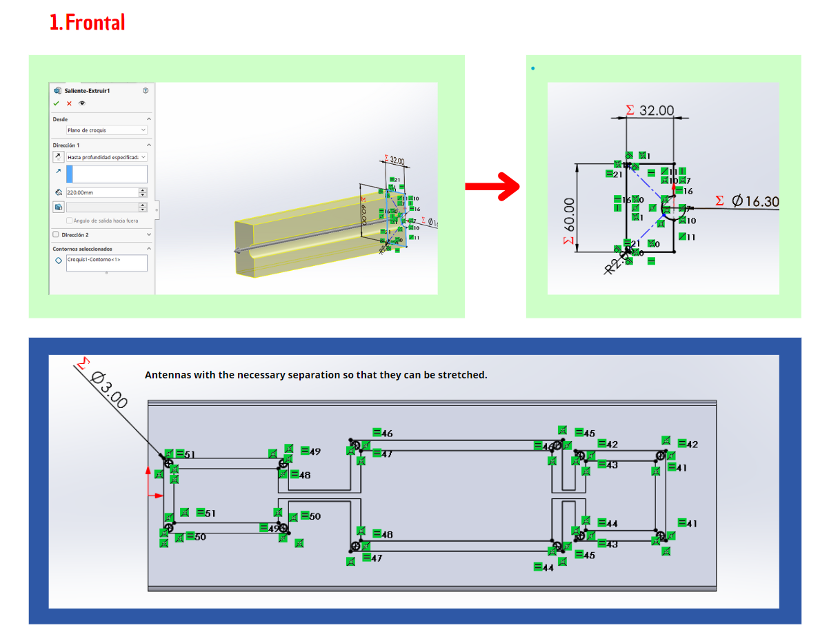
The idea is to design modular pieces. I didn't want to attach them permanently to a cane, because the goal is to allow them to be adaptable to any existing cane you might already have. Since the design is parametric, I can easily adjust the measurements, ensuring everything fits perfectly.
Pieces:
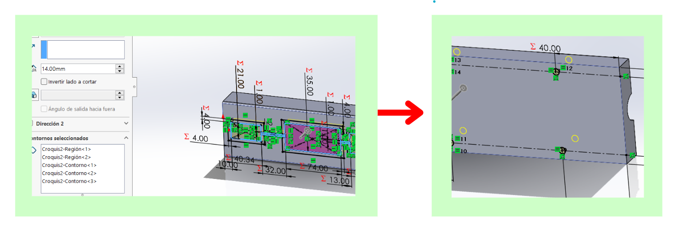
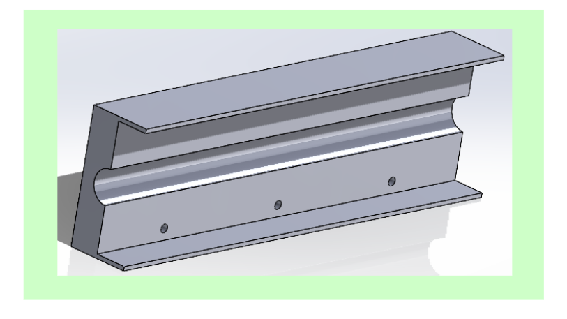
I designed three main parts. The first part, which I call the formal section, houses the sensors, buzzer, and motor. This section is angled at 40° so that the sensors can effectively identify obstacles without getting confused by the floor or other objects that might distract the user instead of helping them.
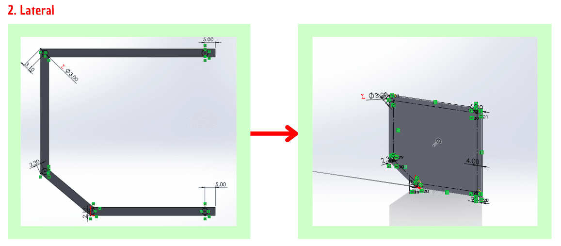
The lateral section exists to make it much easier to install the components. In an earlier design, I found it very time-consuming to place the components, so this lateral part was added specifically to streamline the assembly process.
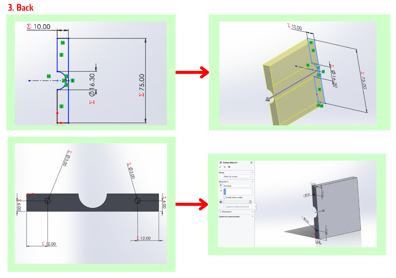
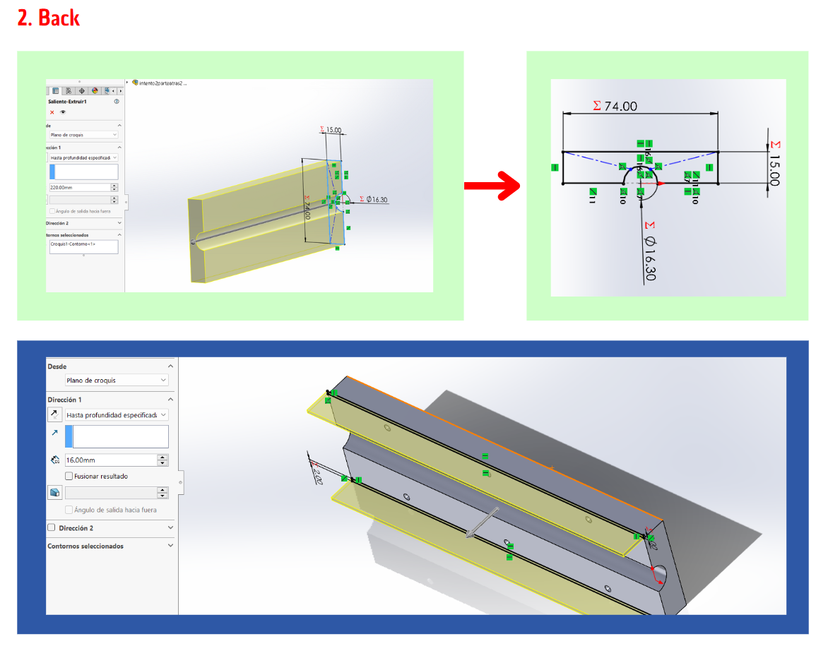
The back section is the counterpart that allows the device to attach securely to the cane. This section has been designed with adaptability in mind. If the cane is slightly larger, this piece can be easily modified to fit correctly. By making minor adjustments to the dimensions of this back section, it can accommodate different cane sizes, ensuring a proper and secure fit. This adaptability not only enhances the functionality of the device but also simplifies the assembly process, making it more versatile and user-friendly. The secure attachment is crucial for the stability of the device, ensuring that all components remain in place and function as intended, providing reliable assistance to the user.
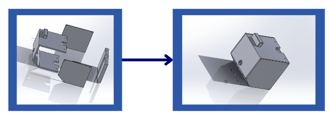
The printer:
To manufacture these parts, I used the X1 Carbon Combo Bambu Lab 3D printer available in our biomedical engineering laboratory. This printer is much faster than others I have used in the past, which is why I chose to use it. Additionally, it provides a much better and cleaner finish, ensuring high-quality, precise parts that enhance the overall functionality and aesthetics of the device.
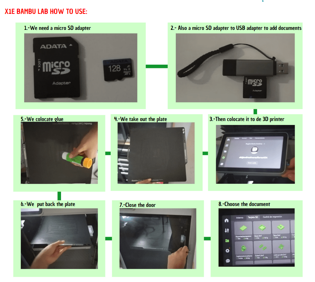
The printing of all the pieces took only 3 hours because the Bambu printer is much faster, which significantly facilitated the work. In contrast, using the Ender printer would have taken more than 6 hours.
The goal was for the pieces to fit any cane, making the design much more efficient. This way, a person can simply attach them to their existing cane without the need to purchase a new one.Here is a video of how everything is collocated inside the 3D print, I didn't wanted to colocate the full video of me joining the parts because it actually took me like one full week.
In this video you can see how it actually works!! It doesn't sounds when it the ground, but when it sees something near the 10 cm, it vibrates and sound depending how close you are:
Here it is another video of the proper functioning:
Development of the Second Part
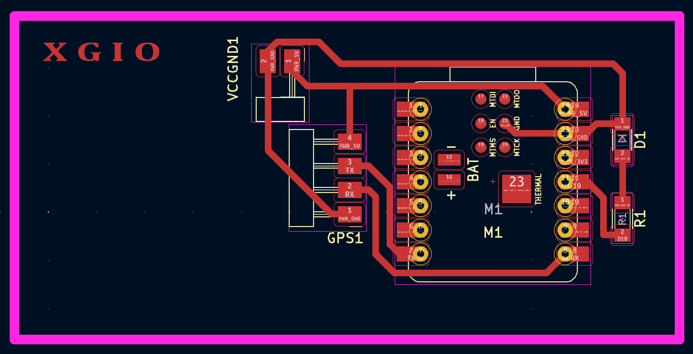
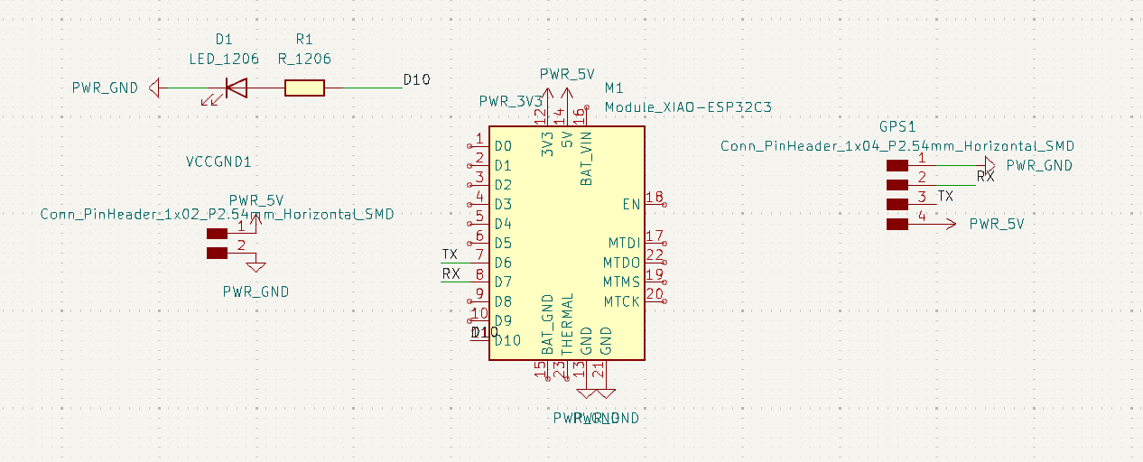
The second part is to implement a type of GPS in the same cane which will have a connection internet and it would tell the person their exact position or location.
The module that is going to be used is the Neo-6m :
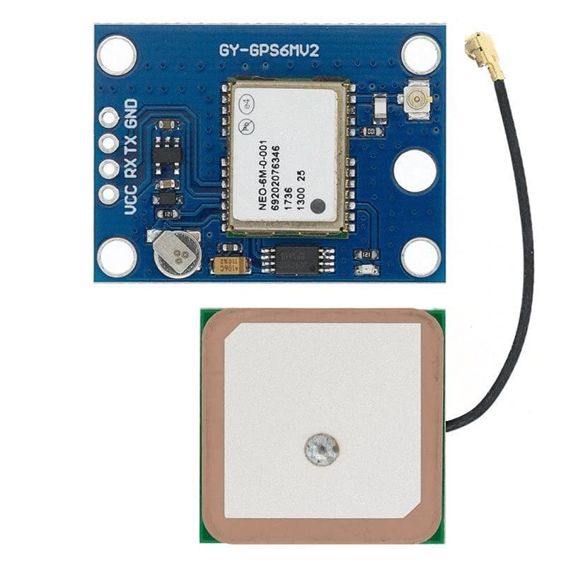
The Neo-6 series by u-blox represents a range of GPS modules designed for efficient and reliable navigation and positioning applications. These modules are known for their high sensitivity, with a tracking sensitivity of -161 dBm, which allows them to perform well even in challenging environments such as urban canyons and dense foliage. The Neo-6 series supports multiple GNSS systems, including GPS and QZSS, enhancing their versatility and accuracy. With a power-efficient design, these modules can operate on low power, making them suitable for battery-operated devices. Additionally, they feature a compact form factor, enabling easy integration into a wide variety of applications, from automotive to personal navigation devices. The modules also offer advanced jamming and spoofing detection mechanisms to ensure robust and secure signal reception.
As you can see in the Week 11, there is my first attempt.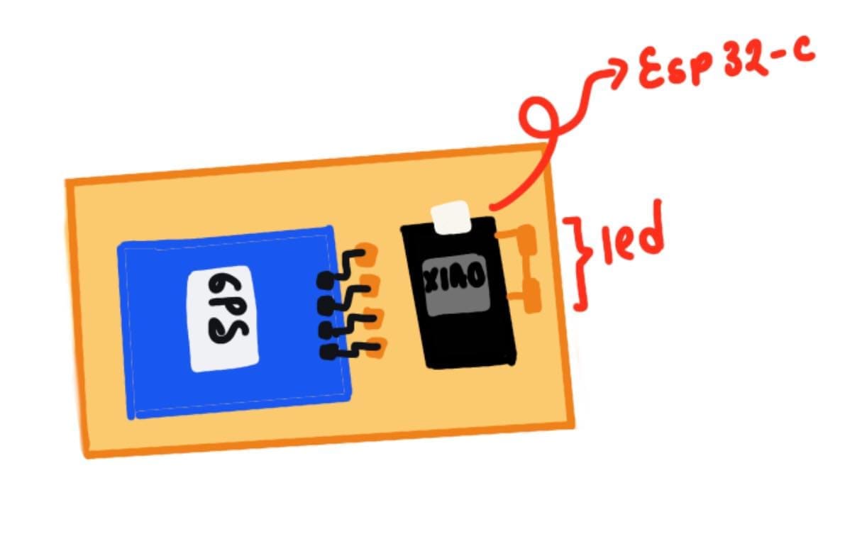
This was my initial drawing of what I wanted to do, this with the purpose of possibly moving everything around and colocate it as the way I wanted.
Here is the visual represetation of the point number 1 explained before.
Here is the visual represetation of the point number 2 explained before.
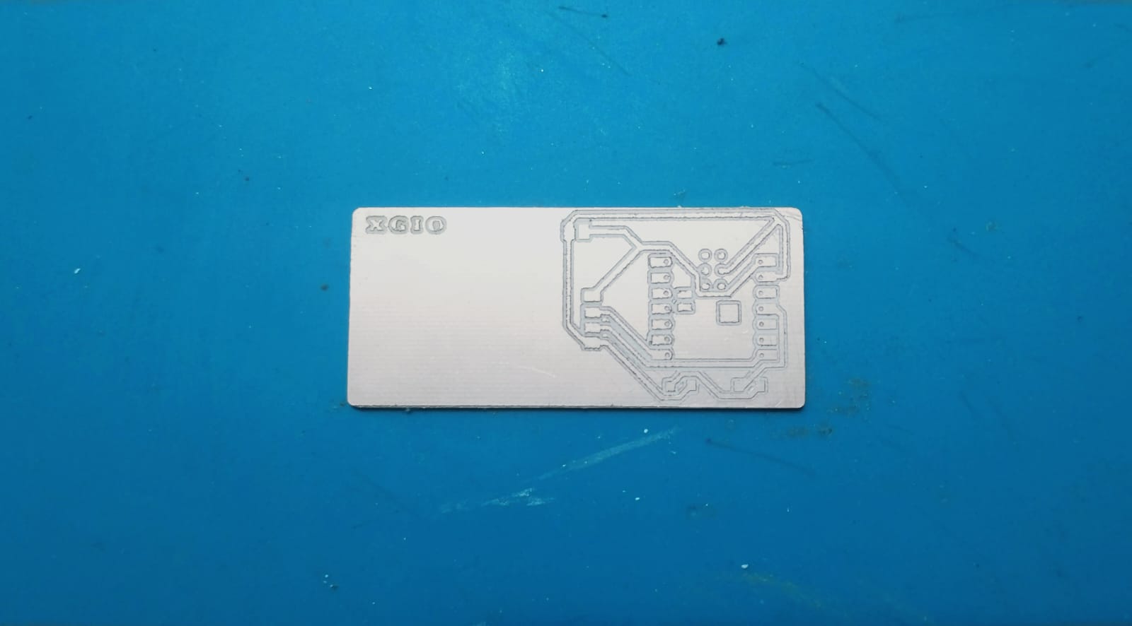
Here is a small clip of how I solded the pieces:
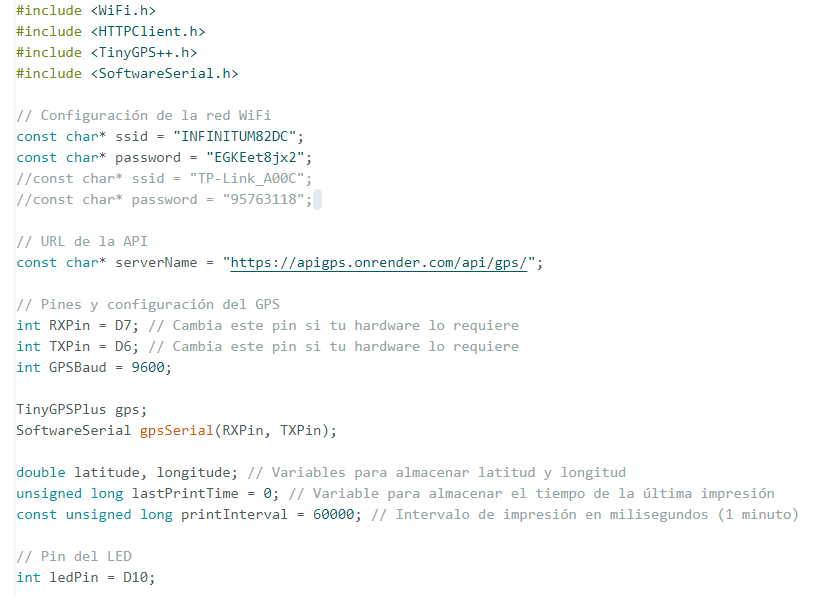
In this part of the code, it connects an ESP32 microcontroller to a specified Wi-Fi network using the SSID and password. It sets up a GPS module via software serial communication, reading data from designated RX and TX pins with a baud rate of 9600. The code also defines a URL for an API endpoint where the GPS data will be sent. Latitude and longitude values are extracted from the GPS data using the TinyGPSPlus library. The GPS data is intended to be sent to the server at regular intervals (every 30 seconds), and an LED connected to pin D10 can be used for status indication. The lastPrintTime variable helps manage the timing for data transmission, ensuring it happens at the defined interval.
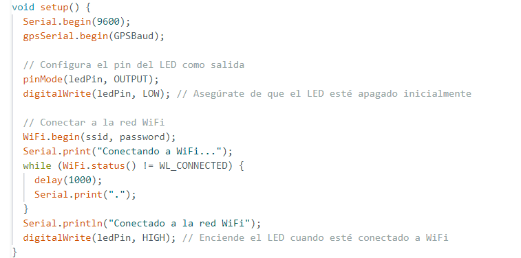
Here it is inizialized serial communication with a GPS module and connects to a WiFi network. In the setup() function, it first initializes serial communication at 9600 baud for debugging purposes and also for the GPS module communication using gpsSerial.begin(GPSBaud). It then configures a specified pin (ledPin) as an output to control an LED, ensuring the LED is off initially. The code attempts to connect to a WiFi network using the provided SSID (ssid) and password (password). It prints status messages to the serial monitor, indicating the connection process. Once connected, it prints a confirmation message and turns on the LED to signal a successful WiFi connection.
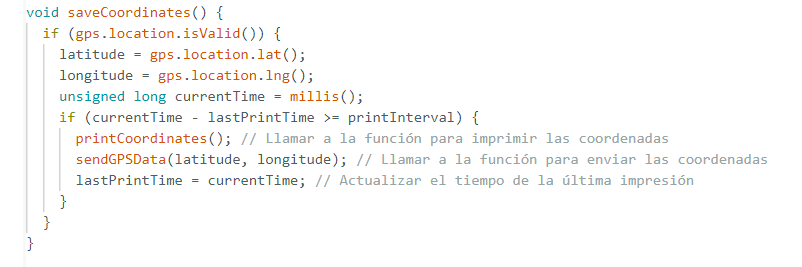
This function saveCoordinates() checks if the GPS location data is valid using the gps.location.isValid() method. If the location is valid, it retrieves the current latitude and longitude values from the GPS object and assigns them to the latitude and longitude variables, respectively. It then gets the current time in milliseconds using the millis() function. The function compares the current time with the last recorded print time (lastPrintTime) to see if a specified interval (printInterval) has passed. If the interval has elapsed, it calls the printCoordinates() function to print the current coordinates and the sendGPSData(latitude, longitude) function to send the GPS coordinates. Finally, it updates lastPrintTime to the current time, ensuring the coordinates are only printed and sent at the specified intervals.
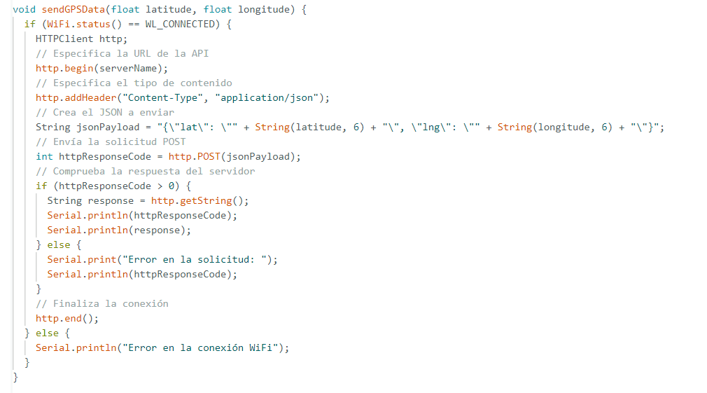
This function, sendGPSData(float latitude, float longitude), is designed to send GPS coordinates to a remote server over Wi-Fi. It first checks if the Wi-Fi connection is active (WiFi.status() == WL_CONNECTED). If connected, it creates an HTTPClient object and specifies the target server URL using http.begin(serverName). The content type for the HTTP request is set to JSON with http.addHeader("Content-Type", "application/json"). The GPS coordinates (latitude and longitude) are then formatted into a JSON string, jsonPayload, with six decimal places of precision. The function sends this JSON payload via a POST request (http.POST(jsonPayload)). It checks the server's response: if successful (httpResponseCode > 0), it prints the HTTP response code and server's response to the serial monitor. If the request fails, it prints an error message with the HTTP response code. Finally, it terminates the HTTP connection with http.end(). If Wi-Fi is not connected, it prints an error message indicating the Wi-Fi connection issue.
Here you can see how the LED is turned on when it is connected to WIFI, and how it is blinking the other LED sending the data:
The idea is to design modular pieces. I didn't want to attach them permanently to a cane, because the goal is to allow them to be adaptable to any existing cane you might already have. Since the design is parametric, I can easily adjust the measurements, ensuring everything fits perfectly.
Pieces:
I designed three main parts. The first part, which I call the formal section, houses the sensors, buzzer, and motor. This section is angled at 40° so that the sensors can effectively identify obstacles without getting confused by the floor or other objects that might distract the user instead of helping them.
The lateral section exists to make it much easier to install the components. In an earlier design, I found it very time-consuming to place the components, so this lateral part was added specifically to streamline the assembly process.
The back section is the counterpart that allows the device to attach securely to the cane. This section has been designed with adaptability in mind. If the cane is slightly larger, this piece can be easily modified to fit correctly. By making minor adjustments to the dimensions of this back section, it can accommodate different cane sizes, ensuring a proper and secure fit. This adaptability not only enhances the functionality of the device but also simplifies the assembly process, making it more versatile and user-friendly. The secure attachment is crucial for the stability of the device, ensuring that all components remain in place and function as intended, providing reliable assistance to the user.
The back section is the counterpart that allows the device to attach securely to the cane. This section has been designed with adaptability in mind. If the cane is slightly larger, this piece can be easily modified to fit correctly. By making minor adjustments to the dimensions of this back section, it can accommodate different cane sizes, ensuring a proper and secure fit. This adaptability not only enhances the functionality of the device but also simplifies the assembly process, making it more versatile and user-friendly. The secure attachment is crucial for the stability of the device, ensuring that all components remain in place and function as intended, providing reliable assistance to the user.
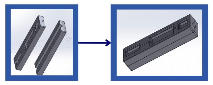
Here is a small video of how all the pieces are put together and how it is colocated to the cane:
I developed the interface almost entirely during the interface development week, focusing on creating a user-friendly and functional design. The only significant addition made afterward was the feature to display the route of the person, which allows users to view and track their path. This specific enhancement will be documented in detail here, providing insights into its implementation and integration into the existing interface.
For a comprehensive explanation of the overall development process and the methodologies used, please refer to: MOBILE INTERFACE: Week 14
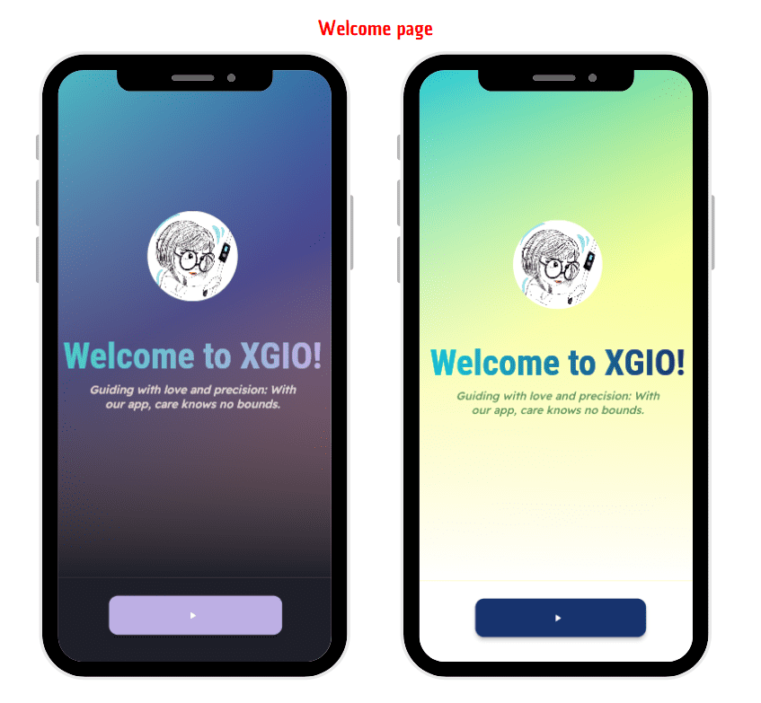
The app comes with two versions: a dark mode and a light mode. These themes can be switched automatically depending on your phone’s settings, ensuring a seamless and personalized user experience. Below, you can see the screens showcasing both the dark and light versions of the app:
- Dark Mode: Designed for use in low-light environments, reducing eye strain and conserving battery life.
- Light Mode: Ideal for bright environments, providing a clear and crisp display for easy readability.
The app begins with a welcome page designed to offer a welcoming and engaging experience upon entry. It features a soothing greeting message accompanied by a prominent play button, inviting users to begin their interaction seamlessly
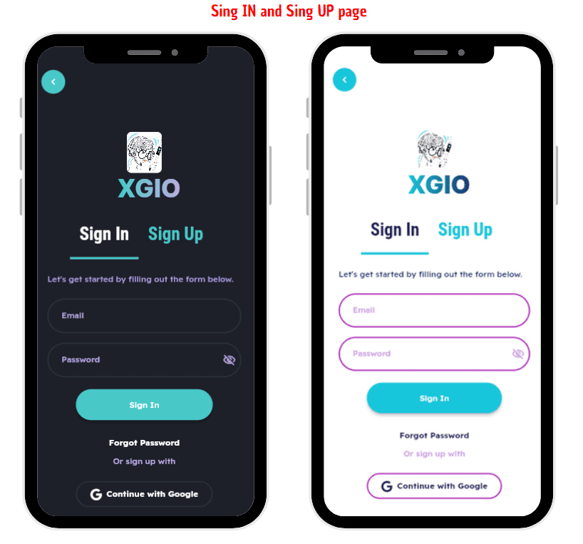
Moving forward, the sign-in and sign-up pages serve as the gateway for users to either create a new account or log into an existing one. This step is crucial as it enables the app to gather specific information about the user, which is essential for providing personalized services.
Once authenticated, users are directed to the main menu page, which houses several key functionalities.
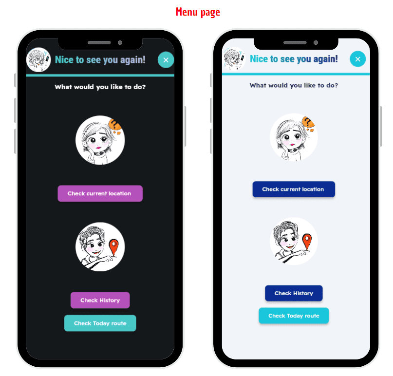
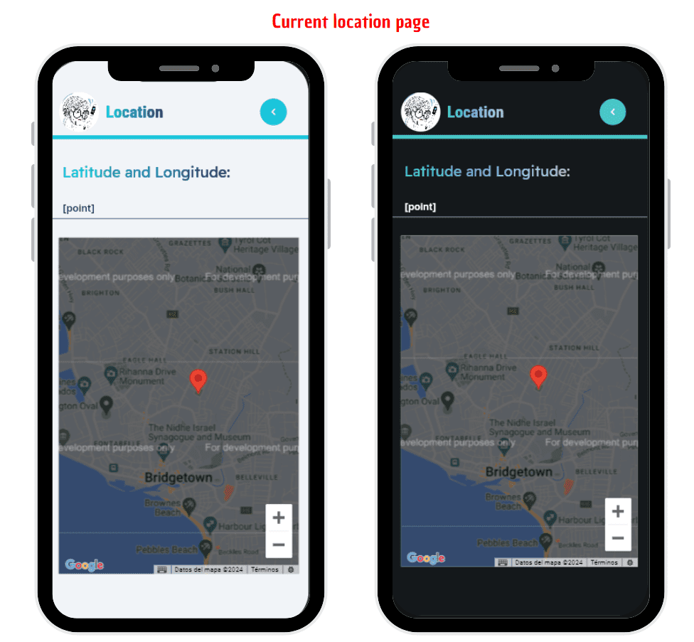
The first option allows users to check their current location in real-time, leveraging the device's GPS capabilities to pinpoint their exact whereabouts. This feature not only provides immediate location details but also ensures users stay informed about their surroundings.
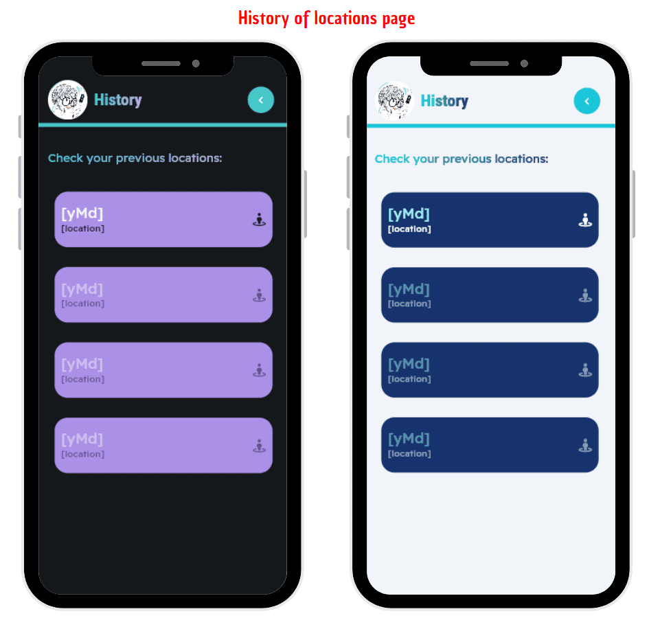
The second option on the main menu is dedicated to viewing route history. Here, users can access a detailed timeline of their movements throughout the day, displaying various points they have visited or passed through. This retrospective view not only aids in recalling past activities but also helps in planning future journeys based on previous routes taken.
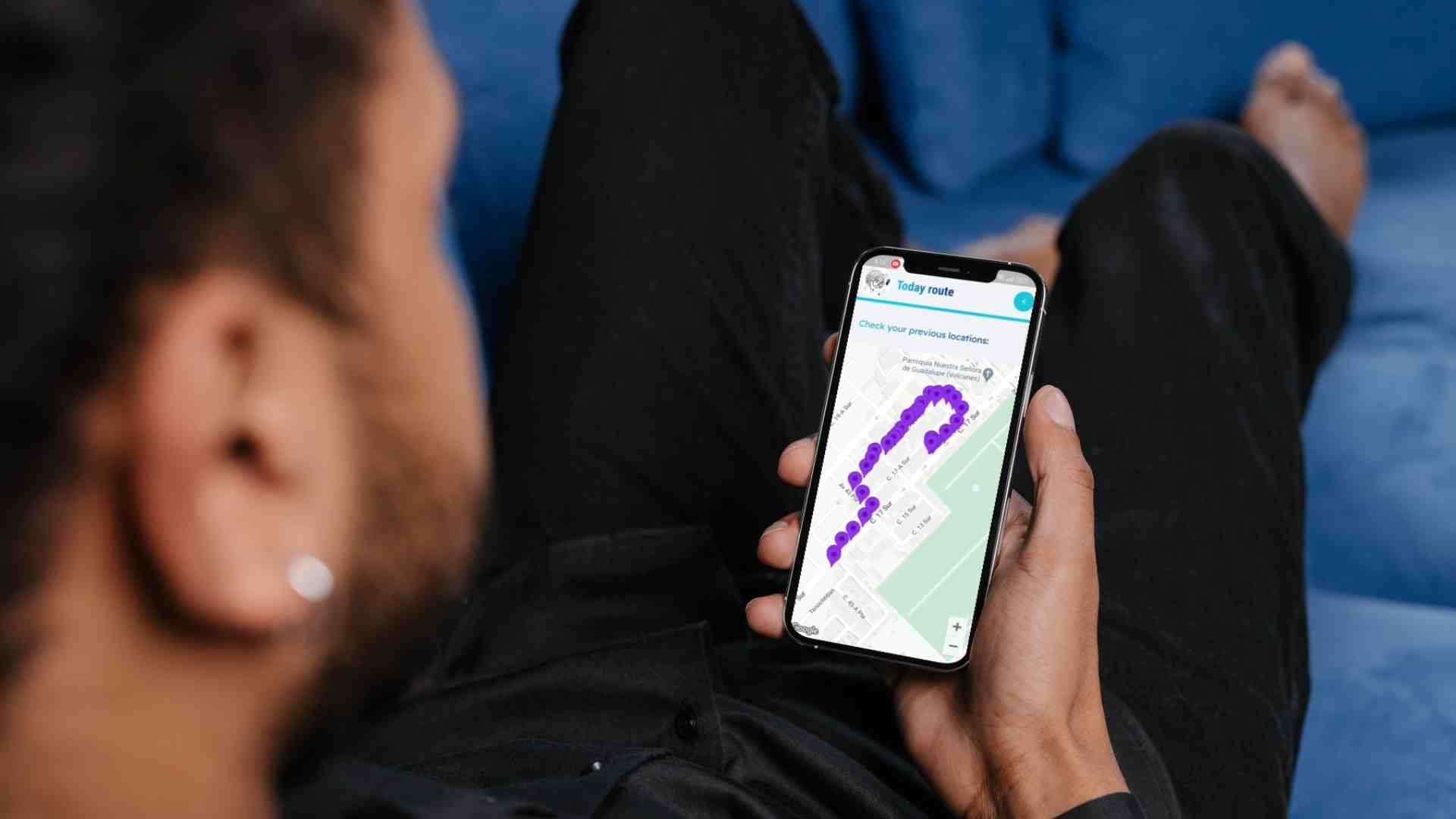
The latest addition to the app is the trajectory tracking feature. This innovative capability aggregates all recorded points of a user's journey and dynamically generates a comprehensive route map. This map visualizes the entire path traveled, offering a holistic view of the user's movements over a specified period. This functionality is particularly useful for analyzing travel patterns, understanding frequented locations, and gaining insights into overall movement behavior.
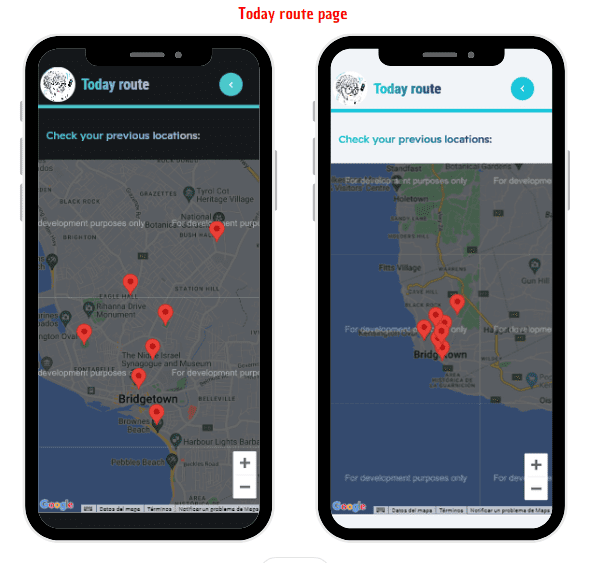
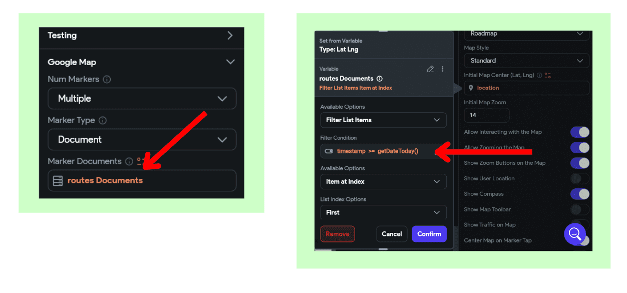
The "Track Trajectory" feature is powered by FlutterFlow and utilizes data from a Firestore collection named "routes." This functionality gathers comprehensive information from the routes recorded on the same day and seamlessly displays them on the map interface, as illustrated below:
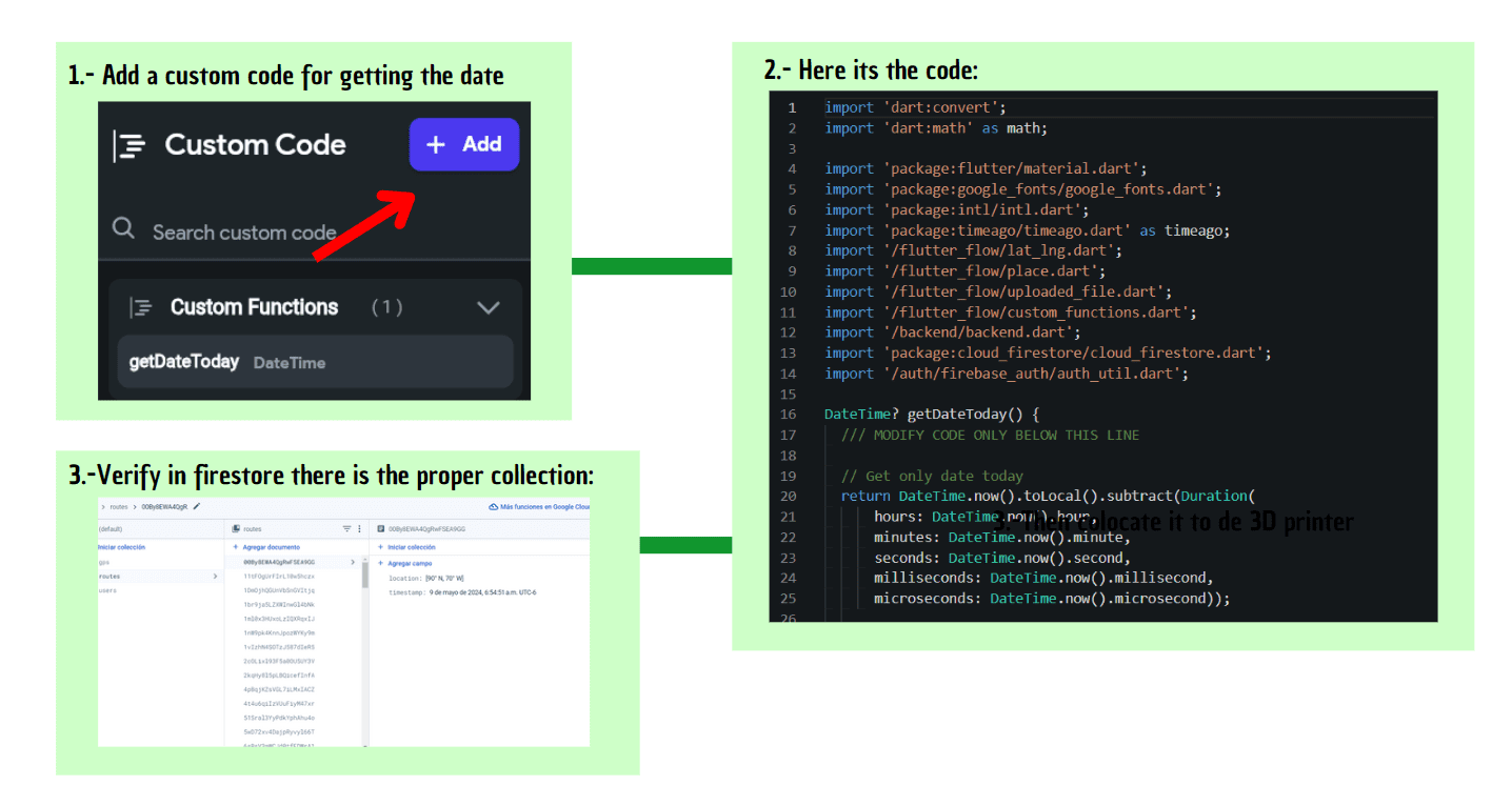
Using FlutterFlow ensures a smooth integration of backend functionality with the frontend user interface, allowing for efficient data retrieval and visualization. The Firestore "routes" collection serves as the repository for storing location-based data, which is then retrieved and dynamically plotted on the map in real-time. This capability not only enhances user engagement by providing a visual representation of their daily trajectories but also leverages cloud-based storage to ensure data reliability and accessibility across devices.
The APK download app was quite heavy to colocate the document, but in case you want to download it make sure to send me a message.

Here I made some mockups I made with Canva Pro, just to give a complete look of how everything will loke like:

Here it's the full video of the functioning of the app, I went for a 30 min walk and this is the video of eveything(I cut it a bit, because I was going tobe heavy):
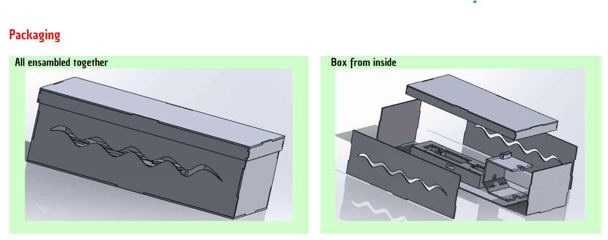
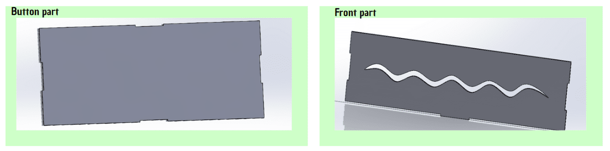
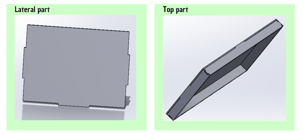
Laser cut
My packaging box consists of five pieces that are assembled considering an MDF kerf of 0.3mm, with the intention of maximizing the use of the machines, specifically the laser cutter. It was originally designed to fit together without the need for glue, but while the pieces did fit, they were not perfectly tight and ended up being loose. As a result, I had to use adhesive to secure them. Additionally, I designed a lid to cover the top of the box, with its pieces also fitting together.
I don't have a better video of the laser cutting because the area was about to close, so they let me cut it very quickly, but with a lot of pressure. However, since it turned out very well, I only had to cut it once, so I couldn't re-record it. It would also be a waste of material to cut another box:
The entire project was designed in SolidWorks, applying the knowledge acquired in recent weeks to create the designs.
Here is a small video of the packaging of my project, I wanted to go beyond of just the project.
Vinyl cut
I made a vinyl cut of letters, the FabLab logo, on and off letters and a cane to be adhered to the lid of the box. It's important to mention that I utilized the knowledge applied in: VINYL CUT: Week 3
The process involved tracing the entire sticker design in Inkscape to create a precise outline. I then saved the design as a PNG file and imported it into Silhouette Studio, where I adjusted the settings to ensure accurate cutting. After configuring the machine, I loaded the vinyl and executed the cut, resulting in a detailed and clean sticker ready to be applied to the box lid.
As previously mentioned, I will use a CC BY license for this project to help more people. This license allows others to recognize my work while also enabling them to improve upon it and generate new ideas. By sharing it under CC BY, I hope to encourage collaboration and innovation, ensuring that my contributions are acknowledged and that the project can evolve and benefit even more individuals.
For a deeper understanding, refer to: Week 17
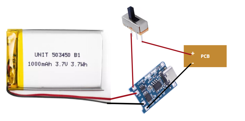
NOTE: for both projects I used a 3.7 V lithium battery with its charger and an switch so I can be rechargable and turn it on and off whenever the person wanted.
A lithium battery was used for this device. Lithium batteries are known for their high energy density, lightweight, and long lifespan compared to other types of rechargeable batteries. They are commonly used in portable electronics, electric vehicles, and other applications where weight and efficiency are critical. Despite these advantages, during constant use, this particular lithium battery lasts approximately three hours before needing to be recharged. This duration can vary depending on the specific power demands of the device it powers.
Mistakes and how I solve them
| Problem | How we solve it | I wanted the GPS module to be soldered as close as possible to the PCB to optimize space and connection. However, in the process, I accidentally applied too much heat with the soldering iron and ended up burning the module, rendering it unusable. | I had to purchase another GPS module to replace the burned one. This time, to avoid the same issue, I soldered pins to the module and cut them short to make it easier to handle and solder without the risk of overheating. |
|---|---|
| I bought a GPS module from an unreliable store, and as a result, the module never managed to fix the location. I spent a lot of time trying to make it work but eventually had to accept that it was a defective module. | I decided to buy a third GPS module, this time from Amazon, to ensure I received a quality product. The new module worked perfectly, solving the location-fixing issue. |
| I designed an enclosure for the laser module without considering the necessary tilt for the sensors. Because of this, the laser sensor constantly detected the floor and triggered the alarm sound, causing a malfunction. | I redesigned the enclosure, incorporating a 45° tilt for the sensors. With this new design, the sensor stopped detecting the floor but still detected certain obstacles, solving the false alarm problem. |