Computer controlled cutting
Group assignment
- Characterize your lasercutter’s focus, power, speed, rate, kerf, joint clearance and types.
- For this first point I used the lasercutter: CAMFive CFL-CMA1080K

- As you can already see in our Group webpage, there are serveral steps you can follow to use the lasercutter(make sure to check first it is the same model, because each lasercutter has different caracteristics).
- For this first point I used the lasercutter: CAMFive CFL-CMA1080K
- Explain what I learned.
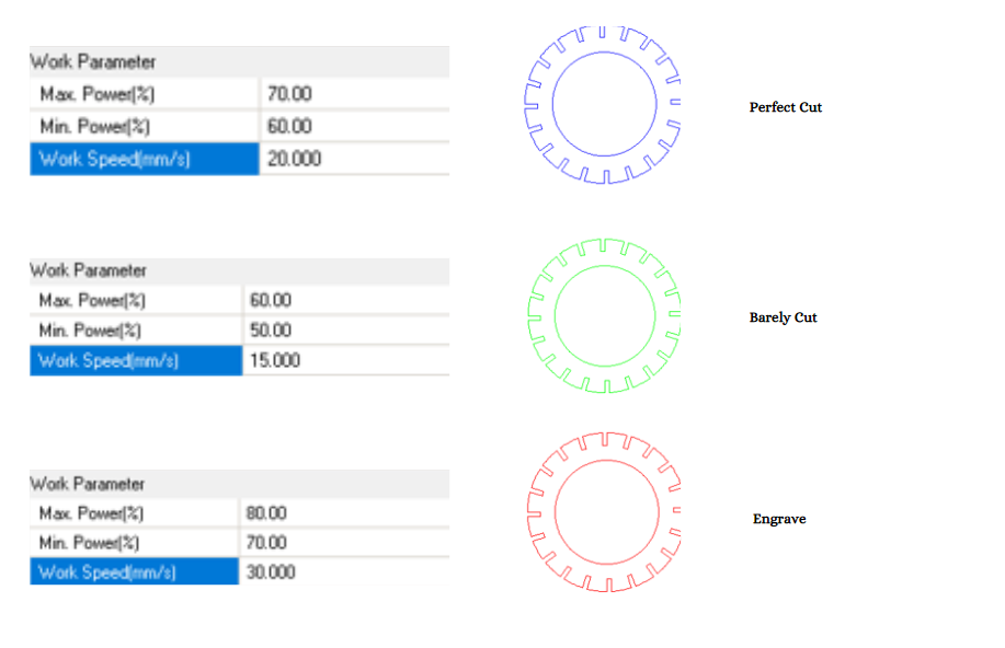
Power and speed
For the first experiment it was used from 10% until 95% of power, and also in speed starting from 15mm/s until 40mm/s; from this it was discovered that:
At slower speed it become really burn wich means = worst kerf.
Kerf
On a MDF 3mm and Acrylic 3mm, it was followed a formula of = gap/number of cuts.
At slower speed it become really burn wich means = worst kerf.
Joints
On the group activity there were several options of joints, such as: snap fit joint,finger joint,wedge joint, pinned joint,press fit joint and flexure joint.
Also I learned to do a living hinge, which are widely used in product design for flexible joints in toys, furniture, possible clothes, etc.
Individual assignments
- Design, lasercut, and document a parametric construction kit, accounting for the lasercutter kerf, which can be assembled in multiple ways.
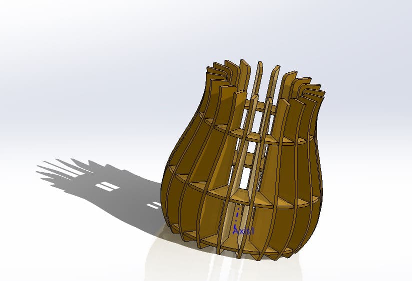
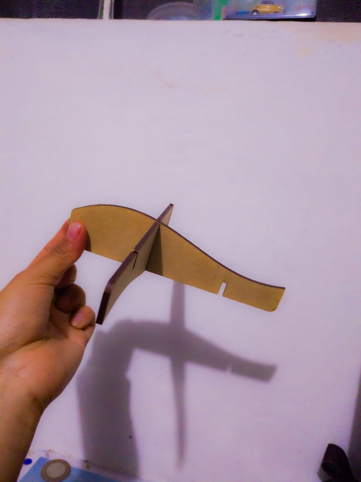
- First I designed a drawing using the knowledge of the week 2 in order to make a flower vase.
- I created the base that was going to be de part that was going to be assembled with some circles that I revolved from the same sketch.
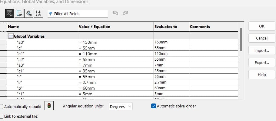
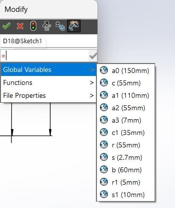
- In the "Tools" menu, select "Design Table" or "Equations" to add parameters to your model. You can set dimensions as variables to facilitate future modifications.
- If you need to make changes to the design, you can adjust dimensions directly in the design table or equations.
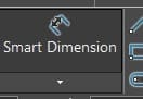
- Use the "Smart Dimension" tool (located on the Sketch tab) to apply dimensions to your sketch. Click on the tool, then select the entities you want to dimension.
- After applying a dimension, you can link it to a parameter by typing an equal sign (=) and then assigning a parameter name. For example, if you want a dimension to be driven by a parameter named "Width," you would enter "=Width" after setting the dimension.
- After you had done that, it should appear a "∑" before the name of the global variable.
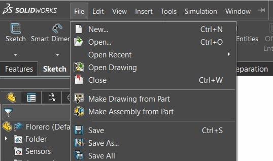
- Open the SolidWorks part or assembly file that you want to save as a DXF.
- Go to the "File" menu and select "Make Drawing from Part" or "Make Drawing from Assembly," depending on your file type.
- Once you have set up the drawing, go to the "File" menu and choose "Save" or "Save As" to save the drawing file (.slddrw).
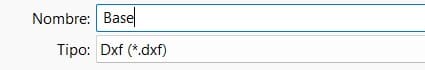
- In the "Save As" dialog box, choose a location to save the file and select "DXF (*.dxf)" as the file type.
- Click on the "Options" button in the Save As dialog box to configure the DXF export options. You can specify things like the version of DXF, sheet scale, and other export settings.
- After configuring the options, click "OK" to close the Options dialog box.
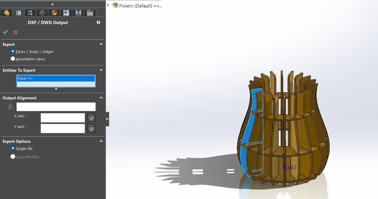
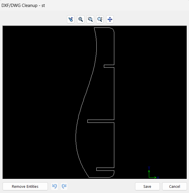
- In Solidworks it appears you a page were you can choose if you want a face, a solid, or anything for your dxf document, and you can previsualize it.
- Also I saved this three more parts for my parametric kit
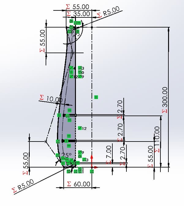
- As it is parametric you can change the measures in the parametric tool and see how quickly it change and you can have differnt forms of the same solid.
- Remember to turn on the machine's fan using the button located on the lower left side.
- Turn on the machine using the button located on the right side.
- Insert the machine key and turn. The lock is located on top of the machine to the right Turn on the laser by pressing the button. The button is located next to the key
- Place the material you wish to cut on the worktable, ensuring it is securely fastened and level. Ensure the material is within the maximum dimensions allowed by the laser cutter.
- Ensure the electronic key is connected to the computer to allow the cutting software to open.
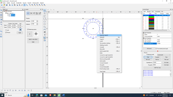
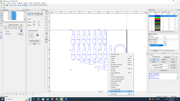
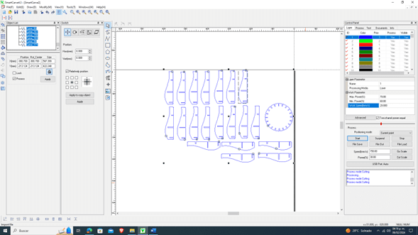
- Open the laser cutter control software "Smart Carve" on the computer.
- Import the design or drawing you wish to cut, ensuring you pick the unit system used
- Launch the Smart Carve software on your computer.
- Look for an "Open" or "Import" option in the menu or toolbar of Smart Carve. Navigate to the location where your document is stored and select it.
- Common file formats for laser engraving/cutting include SVG, DXF, AI, BMP, and other vector or raster formats depending on the capabilities of your machine.
- Once your document is loaded, you may need to adjust settings such as laser power, speed, and resolution based on the material you are working with and the desired result (what we learnt form the group homework)
- Use the tools in Smart Carve to position your design within the work area. You may be able to move, rotate, or resize the design as needed.
- Once satisfied with the settings and preview, look for an option to send or start the job. This usually involves transferring the design and settings to the laser engraving or cutting machine.
- Make sure to follow all safety guidelines for your laser machine. This may include wearing appropriate protective gear, ensuring proper ventilation, and securing the workpiece.
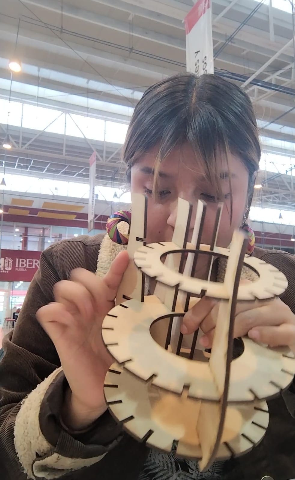
- Here is the kit mainly of 4 pieces that essentially is a flower vase, but you can also do different things.

- Here is a fast video and an image of me doing the assembly of the flower vase.
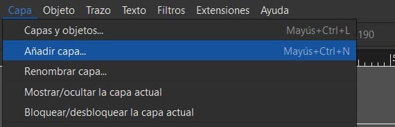
- Open Inkscape:Launch the Inkscape application.
- Go to File and import the image of the shape I want to vectorize:Navigate to the "File" menu and select the option to import the image of the desired shape that you intend to convert into a vector graphic.

- Once the image is placed in Inkscape, add a layer on top for referencing during tracing: After importing the image, create an additional layer above it. This new layer serves as a reference, allowing you to trace the image accurately without directly altering it.
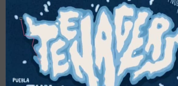
- Use the tracing tool to outline the desired elements, then reshape with the molding tool:Utilize the tracing tool to mark the specific elements you want to vectorize. Subsequently, employ the molding tool to modify and shape the traced elements according to your preferences while ensuring they align with the original image.
- To export for vinyl cutting, separate areas designated for blue and white colors: Identify and distinguish the regions on your design that are intended to be cut from blue vinyl and those from white vinyl. This separation is crucial for the subsequent cutting process.
- Navigate to the File menu, select Export, and choose PNG format:Access the "File" menu, then choose the "Export" option. In the subsequent window, select the PNG format as the preferred file type for saving.
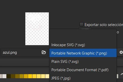
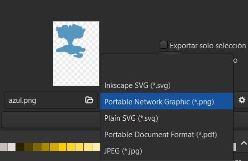
- Repeat the export process for both letters and background: Apply the export procedure separately for the lettering and the background components of your design.


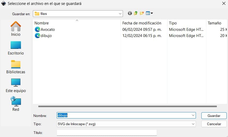
- Save the document as an SVG file for further editing: Once all the steps are completed, save the entire document as an SVG file. This format preserves the vector nature of the graphics, enabling you to continue editing the design as needed.


- Please navigate to the following link: Silhouettestudio
- On the homepage, you will find the option to download the installer for the respective machine that will be utilized.

- Upon completion of the download, locate the file and proceed by clicking "Next" throughout the installation process to finalize the program setup.

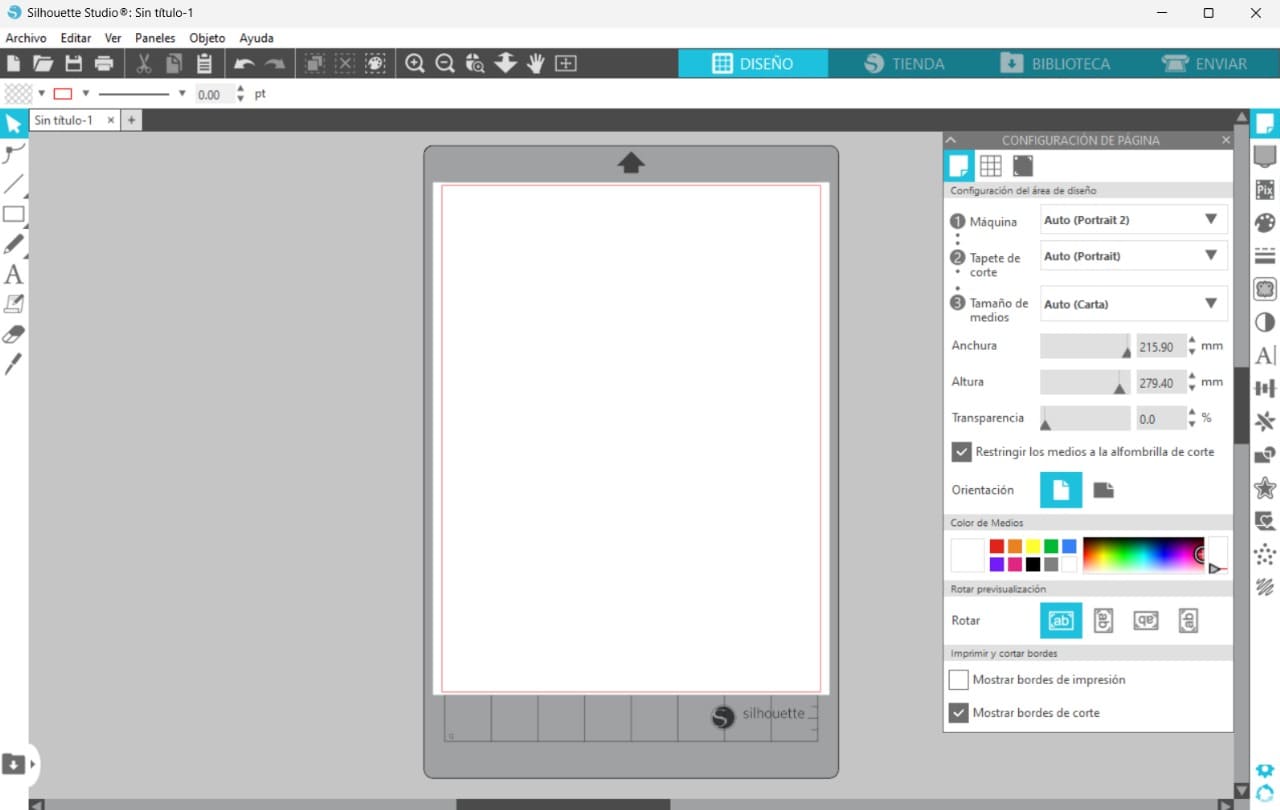
- The application interface is depicted as follows.
- Access the "File" menu, then select "Open" to load a PNG image. This allows you to position the image within the desired space, with options provided for resizing and repositioning based on the central black arrow indicator.
- Repeat this step twice to merge the two stickers into a unified entity.

- Once properly positioned, simply click "Send" (indicated as "Not available" due to the current absence of connection).
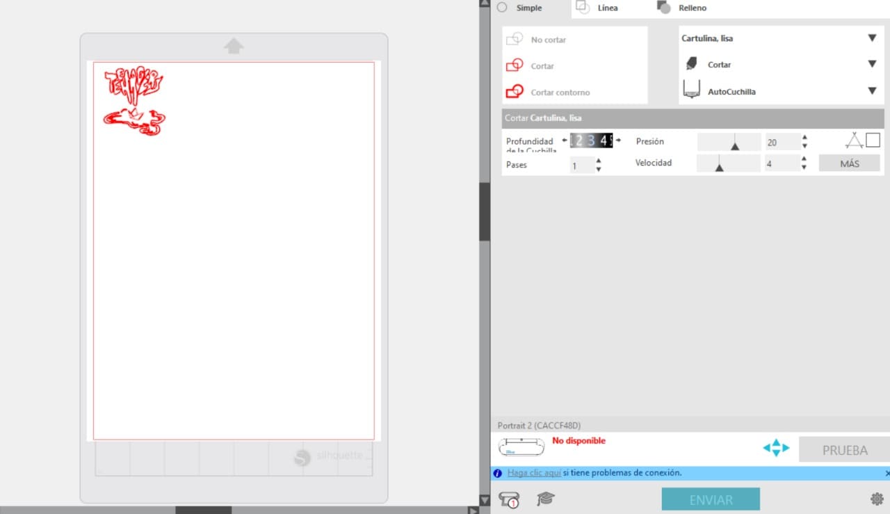
- For this part it was used a Plotter de corte silhouette cameo 4
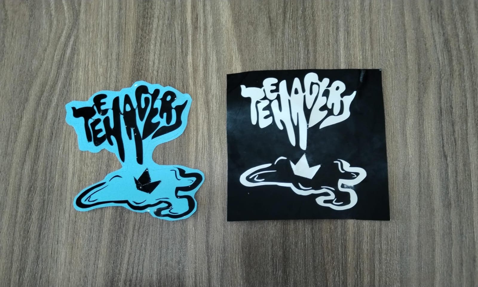
- Here is the cut of the vinyl of the white part (there was no white so I change it to black)
- Here is me putting together both vinyl cuts.
- Solidworks document of the cane.
- Base of the cane DXF
- Circle #1 DXF
- Circle #2 DXF
- Circle #3 DXF
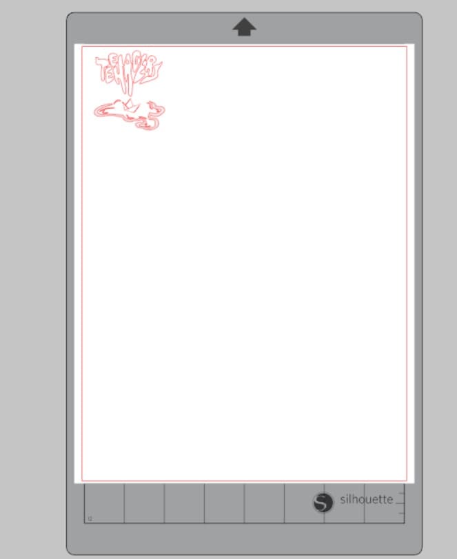
- svg document of the Teenagers sticker.
Design
How to make it parametric

How to save it to cut it in the lasercutter
Original form
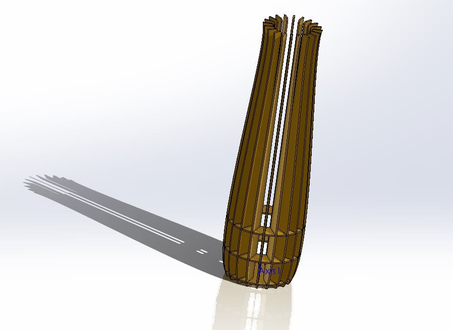
Height instead of 150mm, now 300mm
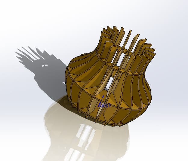
Radius instead of 55mm, now 100mm
Cut it in the lasercutter
Smart Carve
Final result of the many things you can do:
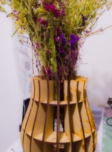
Flower vase
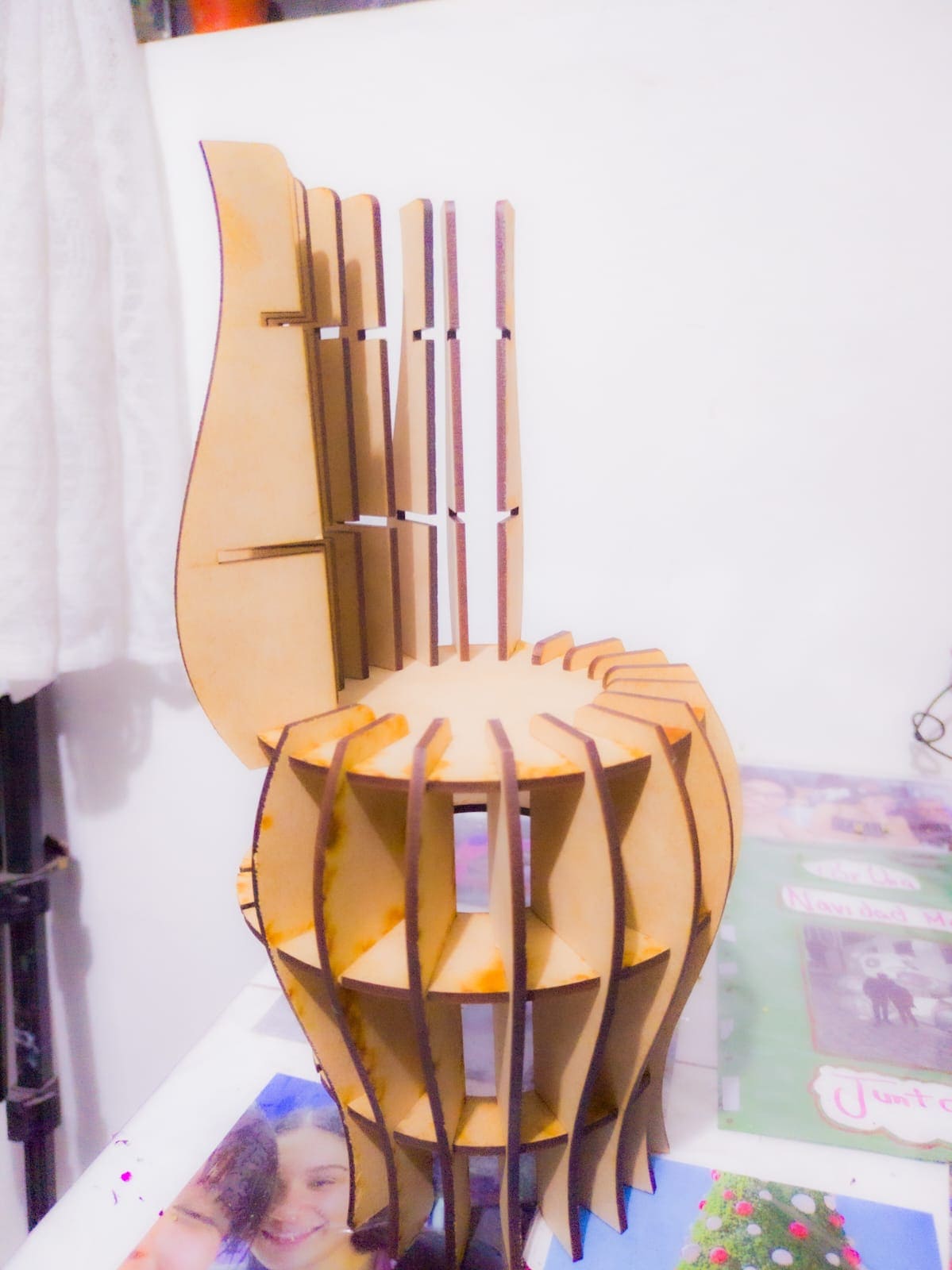
Chair
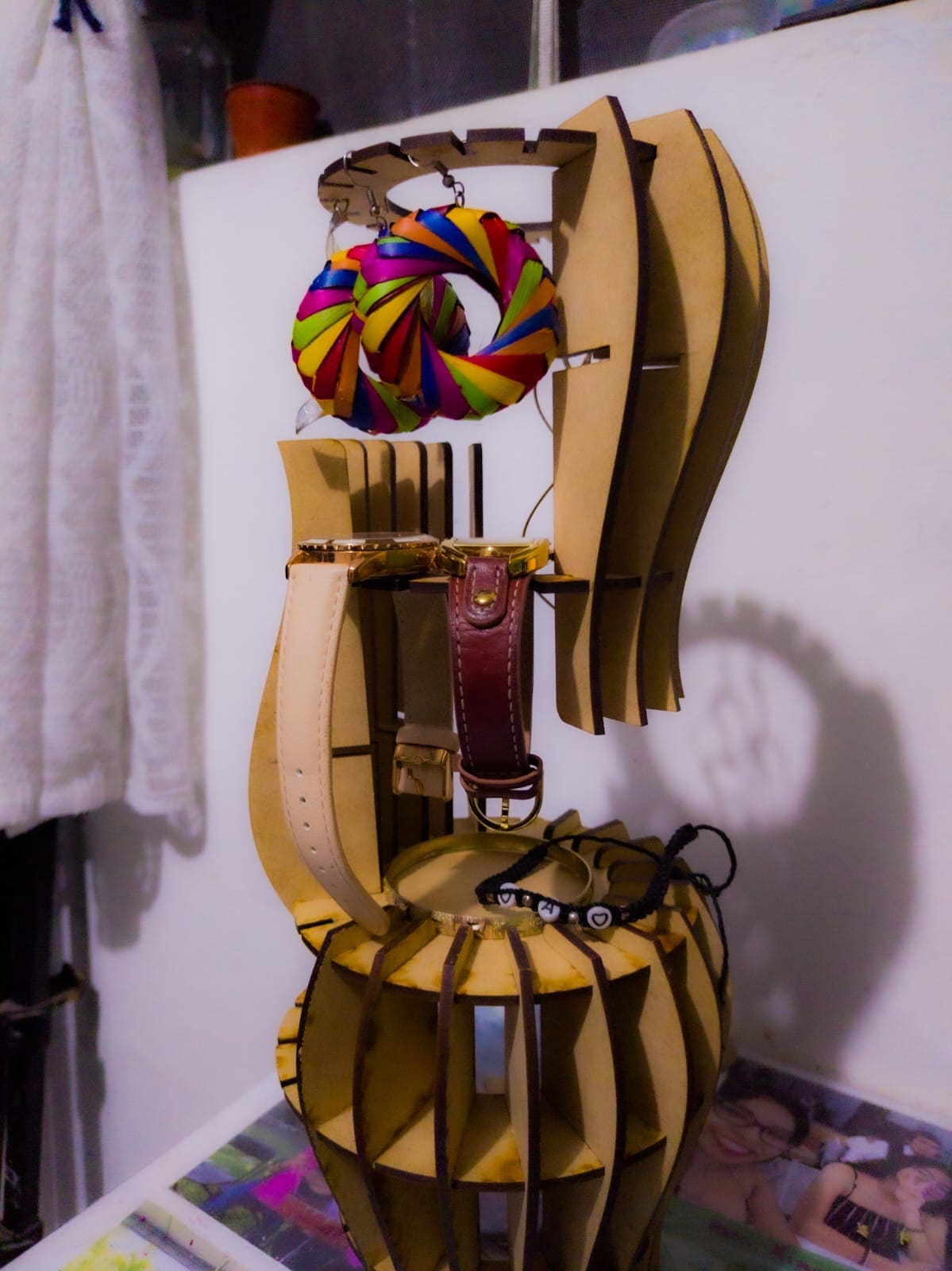
Jeweler
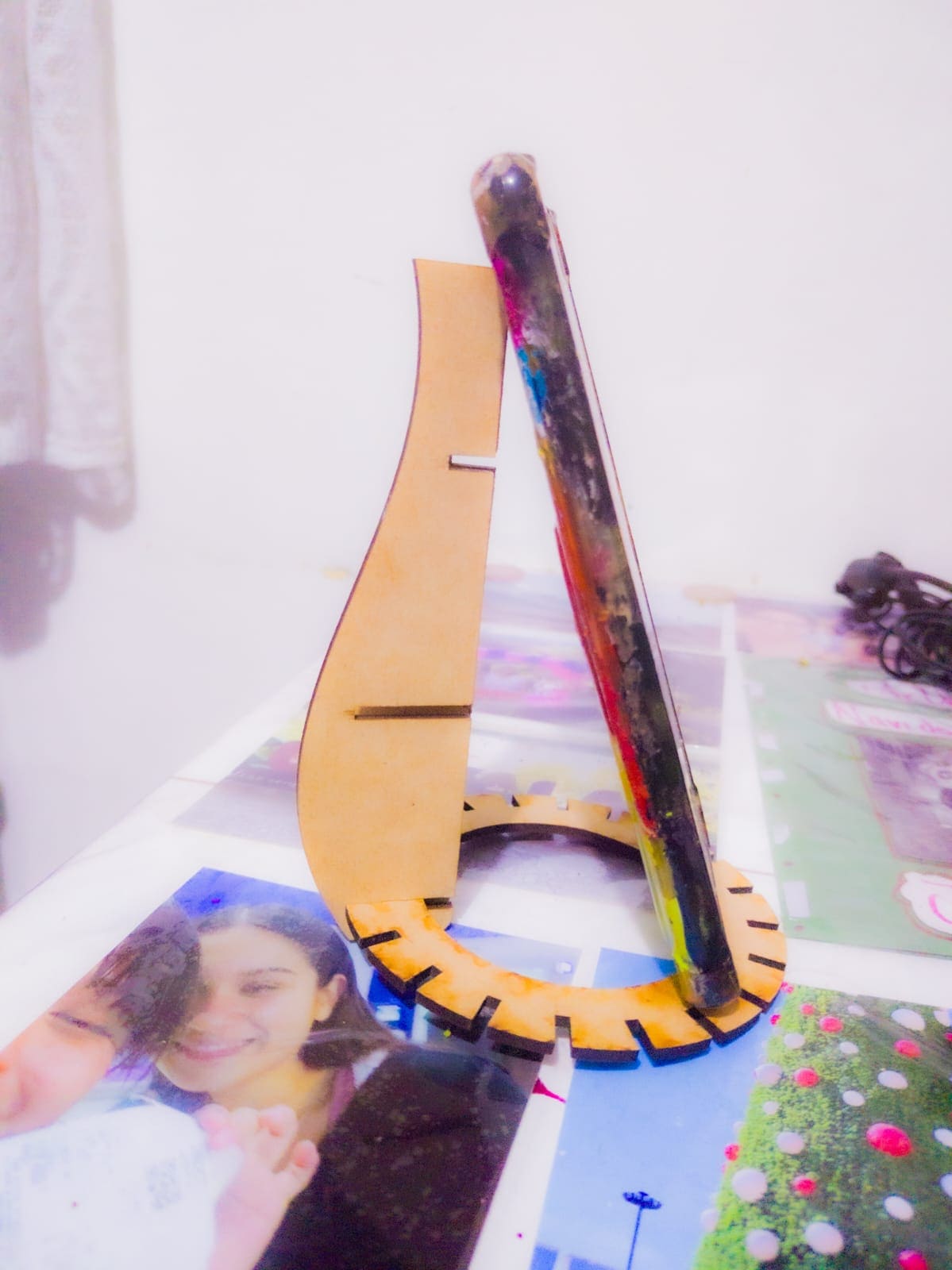
Phone/tablet holder
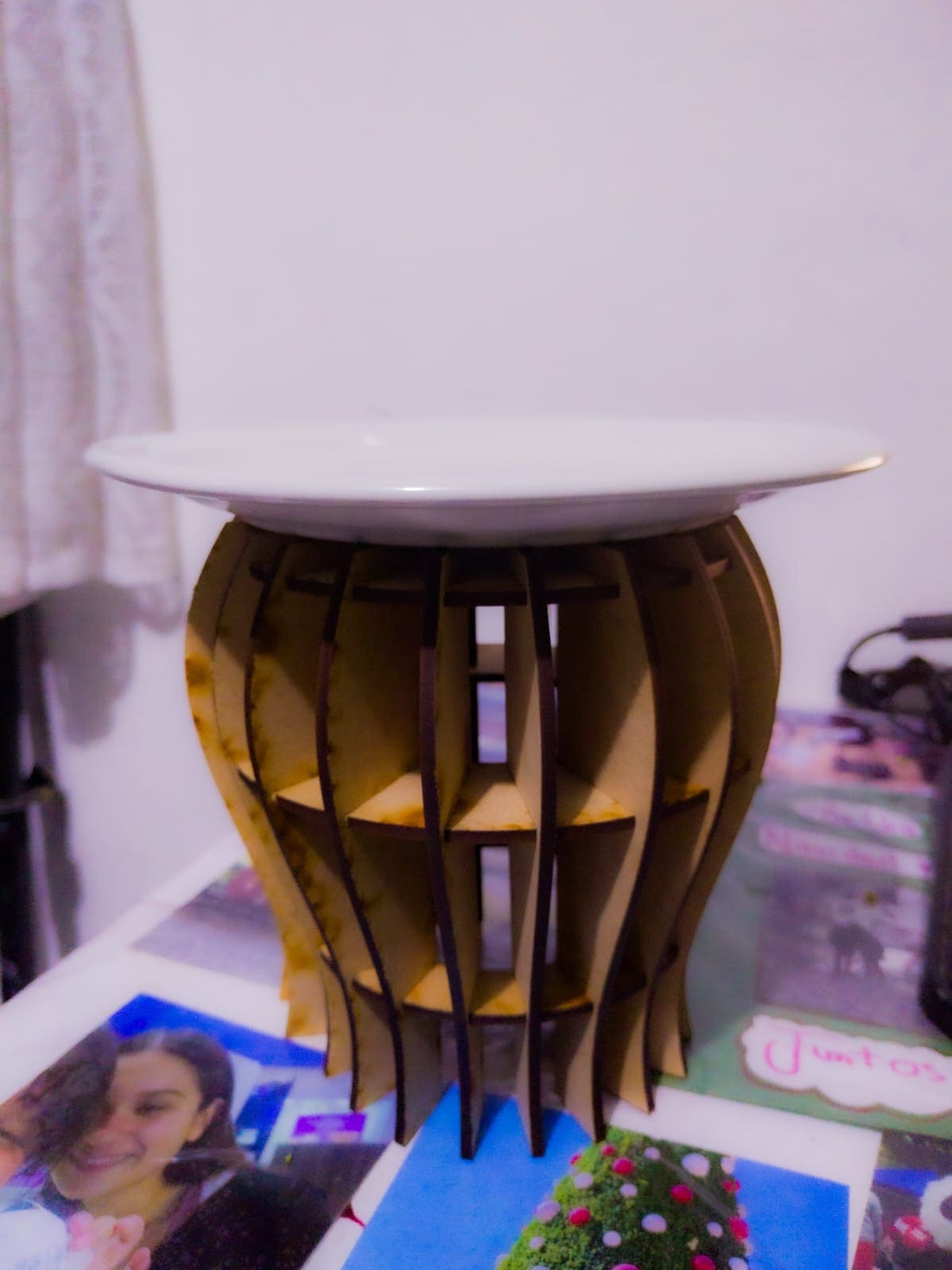
Dessert base
A toy
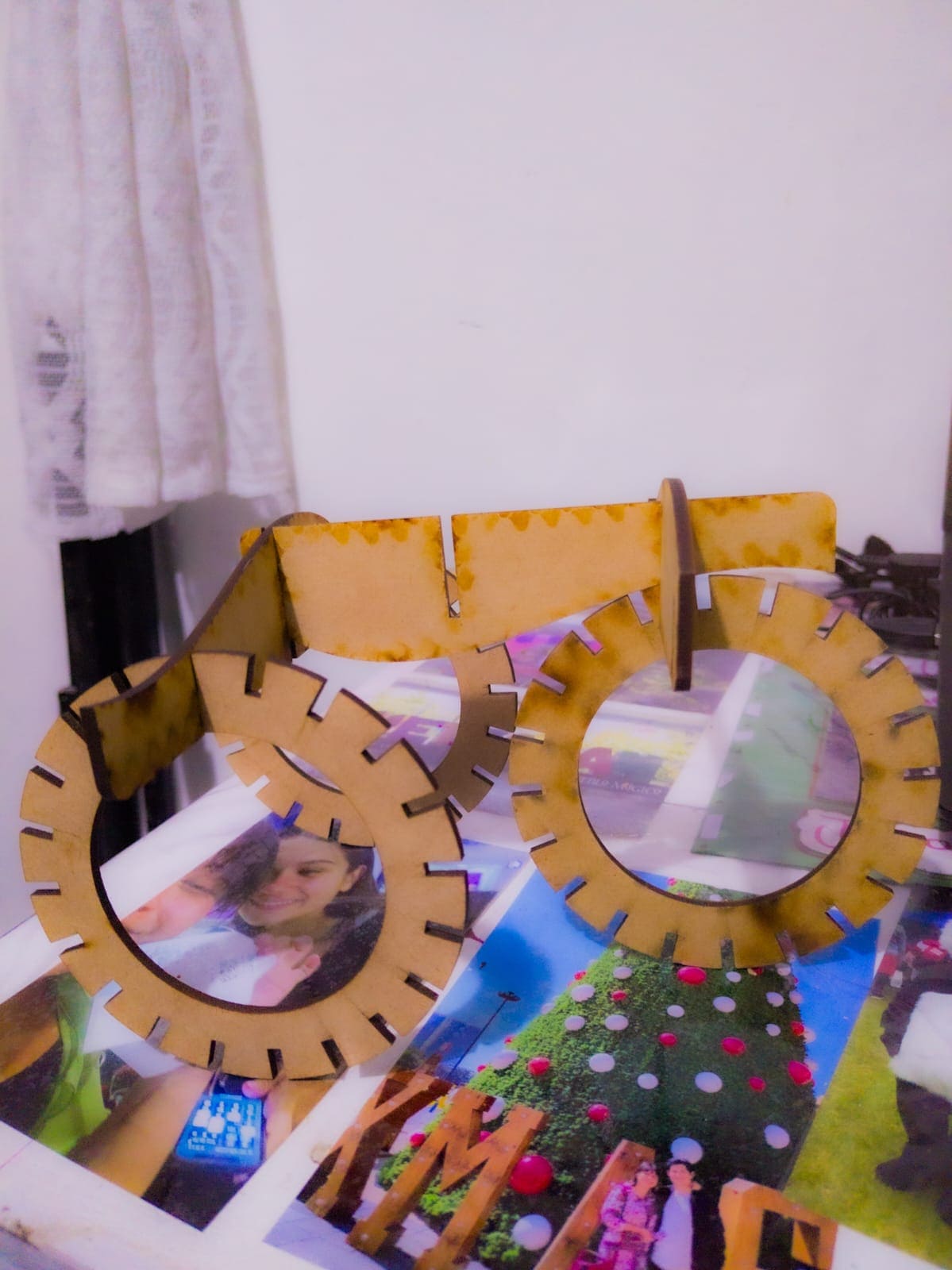
Different toy
Vinyl cutter
Design
For this part of the week assigment I decided to do a sticker of my boyfriend's punk band, so I can gift him for his computer.
Program
Cut in vinyl
Final result