Inputs
Here its our group assigment: Week 11An input typically refers to data or information that is provided to a system, process, or device. In computing, inputs can come from various sources such as keyboards, mice, sensors, or other devices, and they are used to initiate actions, trigger processes, or produce outputs. For example, when you type on a keyboard, the characters you input are sent to the computer as input data, which then processes it to display text on the screen or perform other tasks. Inputs are fundamental in interacting with and controlling computer systems and software.
Individual assigment
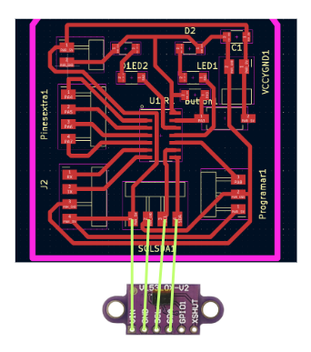
Measure something: add a sensor to a microcontroller board that you have designed and read it.
For this week the idea was to use the sensors I am goint to use for my final project, in this case the following ones:
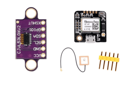
VL53L0X
The VL53L0X is a time-of-flight (ToF) laser-ranging sensor that measures distance accurately up to 2 meters. It utilizes a VCSEL (Vertical Cavity Surface Emitting Laser) and a SPAD (Single Photon Avalanche Diode) detector to emit and detect laser pulses, measuring the time taken for the pulses to travel to the target and back. With its small form factor and low power consumption, the VL53L0X is suitable for various applications such as robotics, gesture recognition, and proximity sensing
Data sheet: VL53L0X
Characteristics:
| Characteristic | Specification | Dimensions: | 0.5″ × 0.7″ × 0.085″ |
|---|---|
| Operating voltage: | 2.6 V to 5.5 V |
| Supply current: | 10 mA |
| Distance measuring range: | From 3cm up to 2 m |
| Supply current: | 10 mA |
Code
This code utilizes a VL53L0X Time-of-Flight (ToF) sensor to measure distance continuously. The sensor communicates over I2C using the Wire library. In the setup function, it initializes serial communication, I2C communication, and the sensor itself, setting a timeout and starting continuous measurement. It configures a pin (A4) for PWM output to control a vibration motor. In the loop function, it reads the distance from the sensor, maps the distance to a PWM range, constrains it within the valid PWM range, and then adjusts the motor speed accordingly using analogWrite. Finally, it prints the distance measured over serial and repeats the process.
Functioning
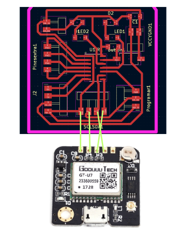
GPS GT-U7
The GT-U7 GPS module is a compact and highly accurate positioning device that utilizes the Global Navigation Satellite System (GNSS) for precise location tracking. Equipped with a built-in antenna and supporting multiple satellite systems including GPS, GLONASS, and BeiDou, the GT-U7 provides reliable positioning data in various outdoor environments. With its UART interface and NMEA protocol compatibility, it seamlessly integrates with a wide range of applications such as navigation systems, vehicle tracking, and outdoor recreational devices. Its low power consumption and fast time-to-first-fix make it an ideal choice for both professional and consumer-grade GPS applications.
Data sheet: GPS GT-U7
Characteristics:
| Characteristic | Specification | Dimensions: | 27.6x26. 6 mm. |
|---|---|
| Operating voltage: | 3.6V-5V |
| Antenna Interface: | IPEX (Default distribution of active antenna) |
| Work Baud Rate: | 9600 (self-modification) |
Code
This code sets up a communication interface with a GPS module using SoftwareSerial library, defining pins for RX and TX, and specifying the baud rate. In the setup function, it initializes serial communication for both the main serial port (presumably connected to a computer for debugging) and the GPS module. In the loop function, it continuously checks for incoming data from the GPS module. When data is available, it reads it character by character into a buffer until it encounters a newline character, indicating the end of a line. It then parses the data if it starts with "$GPGGA", which typically contains fix data. It extracts various pieces of information like UTC time, latitude, longitude, altitude, and units, and prints them out. If there's no fix, it prints "no fix" and breaks out of the loop.
Functioning
Mistakes and how I solve them
| Problem | How we solve it | The first issue I encountered was that the pins were not in the correct order (there were not inverted) | I solved it by using some jumpers and connect it inverted so it could get the signal. |
|---|---|
| The next problem was that my UPDI wasn't functioning as a serial port. | I solved it by asking Adrian through mattermost (THANKS A LOT) and initiating some extra cables for the serial communication in my PCB. |
Documents