Output Devices
Here its our group assigment: Week 9What I learned
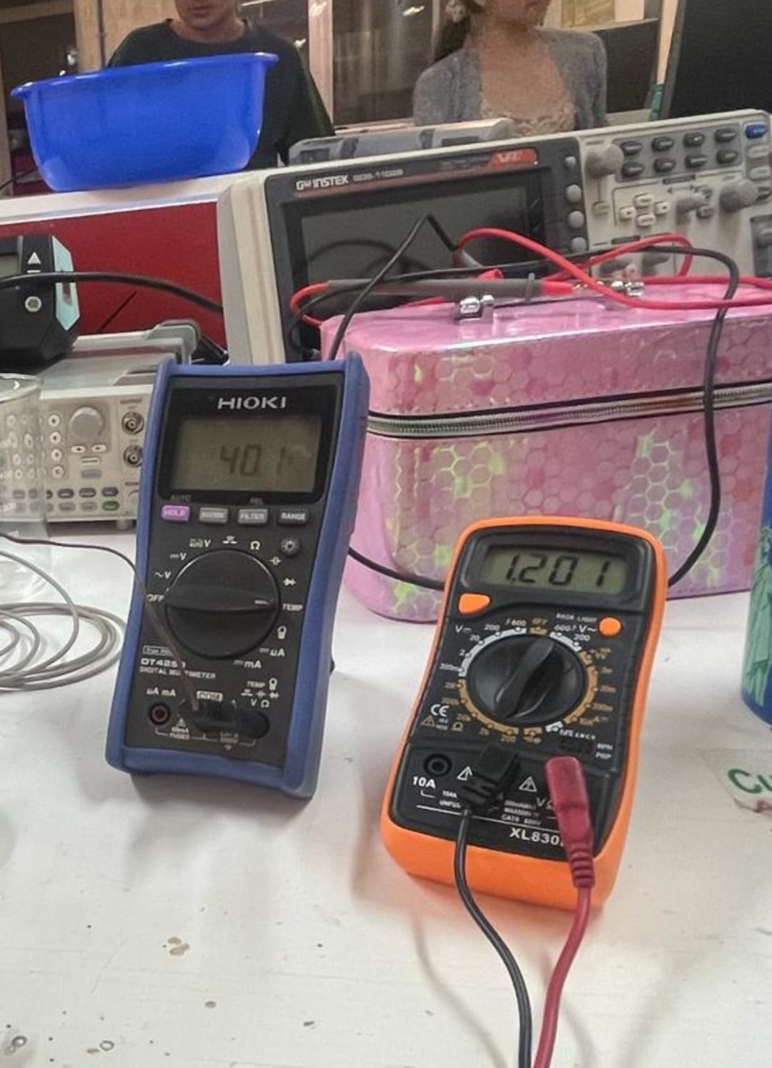
- A multimeter is a versatile tool used to measure various electrical quantities such as voltage, current, and resistance. When observing a microcontroller circuit board, you can use the multimeter to measure voltages at different points in the circuit. This helps in verifying that the power supply is functioning correctly and that voltages are within expected ranges.
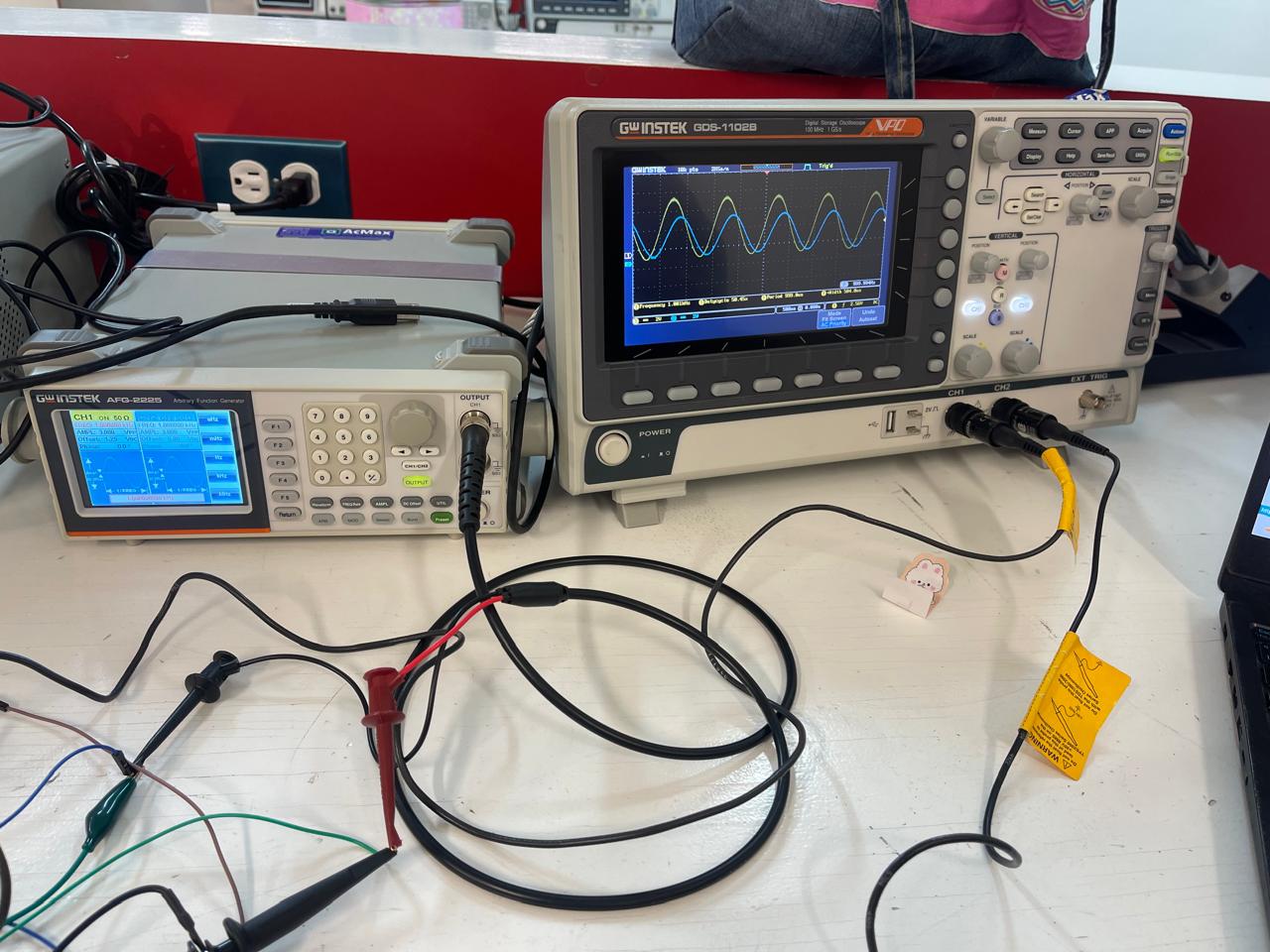
- An oscilloscope is an instrument used to visualize and analyze the waveform of electronic signals. When examining a microcontroller circuit board, the oscilloscope can be used to observe signals at different points in the circuit. This allows you to see how signals change over time, detect abnormalities or unexpected behavior, and verify the proper operation of various components such as sensors, actuators, or communication interfaces.
Individual assigment
Add an output device to a microcontroller board you’ve designed and program it to do something.
Power consumption
- Measuring the power consumption of an output device can be done using various methods depending on the device and available tools.
- A multimeter can also be used to measure power consumption indirectly. By measuring the current flowing through the device and the voltage across it, you can calculate the power consumption using the formula P = VI (where P is power in watts, V is voltage in volts, and I is current in amps).
- For output devices connected to a computer, you may be able to use software tools to monitor power consumption. These tools often come with the device's drivers or can be third-party software.
- Some modern output devices, especially high-end ones like professional monitors or printers, may have built-in power monitoring features.
My board
-
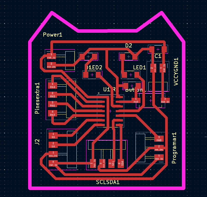
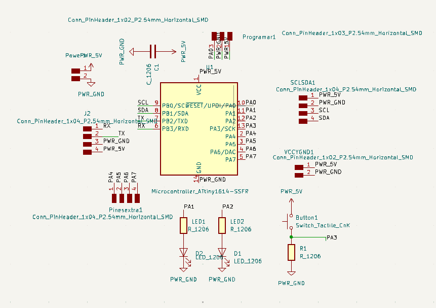
I used KiCad for designing my board, following almost the same steps that in the Week 8
-
It is actually really similar to the last PCB I design but I just changes the places of the pines for programing it, but also some of the structres needed.
-
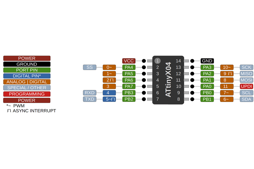
I decided to do use an Attiny1614, because of the week 8 I got really used to it's pins and functioning:
Schematic of my board
Using the machine
I followed the same steps as in the Week 4| Quantity | Material |
|---|---|
| 1 | Attiny1614 |
| 1 | Capacitor |
| 2 | Smd white Leds |
| 2 | Resistor of 1k |
| 1 | Resistor of 2k |
| - | Pines |
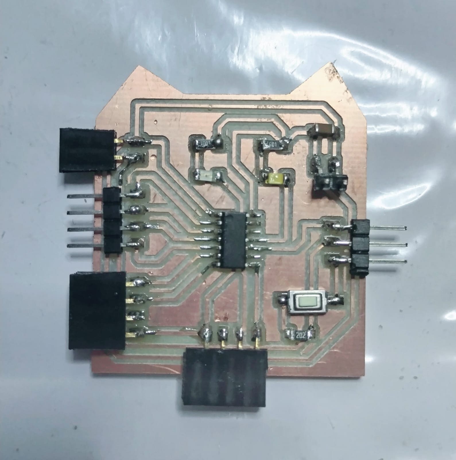
After solding
Programing it
Servomotor
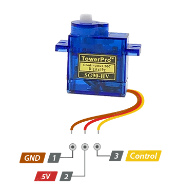
A blue servomotor is a type of servomotor that typically utilizes a blue casing or housing for its components. A servomotor is an electromechanical device that can precisely control angular or linear position, velocity, and acceleration. It operates based on feedback from a control system to ensure accurate positioning. Blue servomotors function similarly to standard servomotors but may have specific features or characteristics tailored to certain applications or environments.
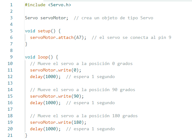
One servomotor
This code in the setup function, the servoMotor is attached to pin A7. In the loop function, the servoMotor is commanded to move to three different positions: 0 degrees, 90 degrees, and 180 degrees, with a delay of 1 second between each movement.
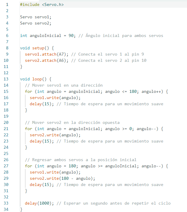
Two servomotors
This code sets an initial angle of 90 degrees for both servos in the setup function. The main loop sequentially moves servo1 from 90 to 180 degrees while simultaneously moving servo2 from 90 to 0 degrees, creating an opposing motion effect. Then, it returns both servos to their initial positions by incrementing servo1 and decrementing servo2 angles from 180 to 90.
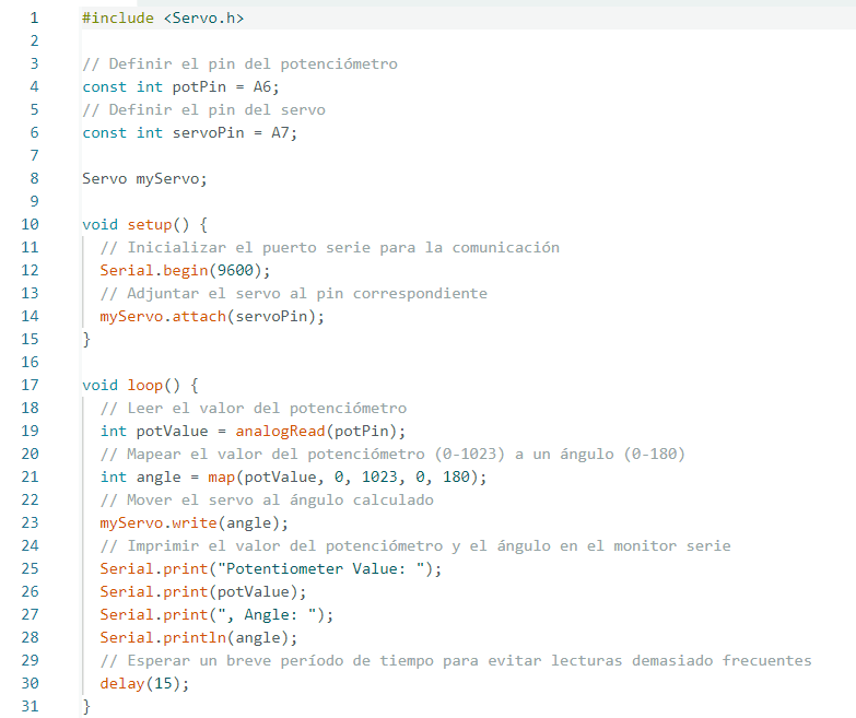
Servomotor with a potenciometer
This code in the setup function, it initializes serial communication and attaches the servo to its designated pin. Then, in the loop function, it reads the potentiometer's value, maps it to a range of 0-180 (suitable for servo angles), moves the servo accordingly, and prints both the potentiometer value and the corresponding angle to the serial monitor.
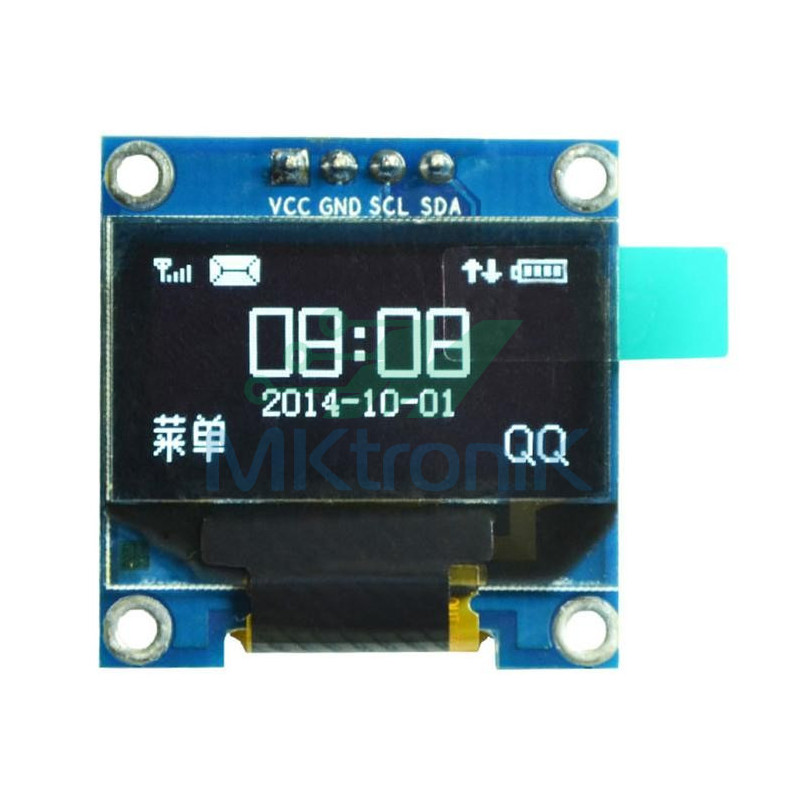
OLED
On the other hand, an OLED (Organic Light-Emitting Diode) screen is a type of display technology used in electronic devices such as smartphones, televisions, and wearable devices. Unlike traditional LCD screens that require a backlight, OLED screens emit their own light when an electric current passes through the organic materials within each pixel. This results in several advantages, including deeper blacks, higher contrast ratios, faster response times, and potentially lower power consumption. OLED screens can also be made thinner and more flexible compared to LCD screens, making them suitable for various applications where space and design considerations are crucial.
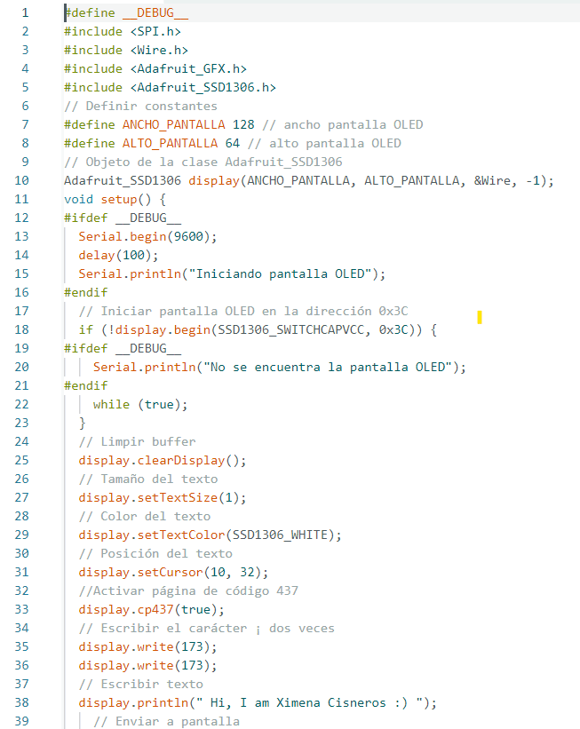
Printing text Oled
This code initializes and controls an OLED display using the Adafruit SSD1306 library. It defines constants for the width and height of the OLED screen, initializes the display, prints a message ("Hi, I am Ximena Cisneros :)") along with some special characters, scrolls the text in different directions (right, left, diagonal right, diagonal left), and utilizes conditional compilation to optionally include debugging messages via Serial communication when the __DEBUG__ macro is defined.
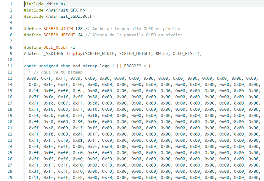
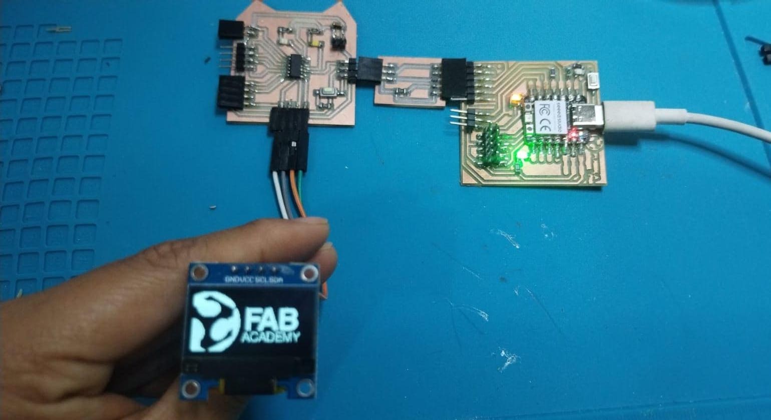
Printing drawing Oled
This code initializes and communicates with an OLED display using the Adafruit SSD1306 library. It sets up the display with specific dimensions, clears it, draws a bitmap defined as "epd_bitmap_logo_1", and then displays it on the screen.
For creating the bitmap for any image, you can enter on this link: http://javl.github.io/image2cpp/
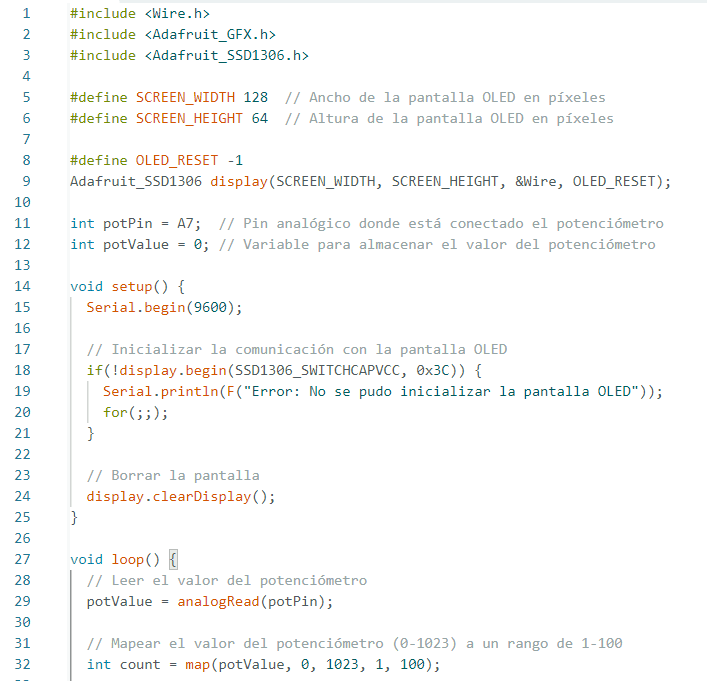
Controlling a potenciomenter and show it on the Oled
This code initializes and communicates with an OLED display using the Adafruit SSD1306 library. It reads the value from a potentiometer connected to an analog pin, maps the value to a range from 1 to 100, clears the OLED display, and then displays the mapped value on the screen. This process repeats in a loop, updating the displayed value as the potentiometer is adjusted.
Don't make the same mistakes as me...
| Mistake | Solution |
|---|---|
| The errors I encountered were primarily due to thinner traces on my PCB, making soldering more challenging | The solution to this issue is either to increase the minimum trace width or add thicker traces where necessary (0.7mm). |
| Another problem was the lack of a direct connection with the UPDI interface, requiring the create another pcb connection instead of a protoboard. | To address this, I cut a new small board that provide easy access to these connections. The connections/squematic of this mini PCB are on week 8. 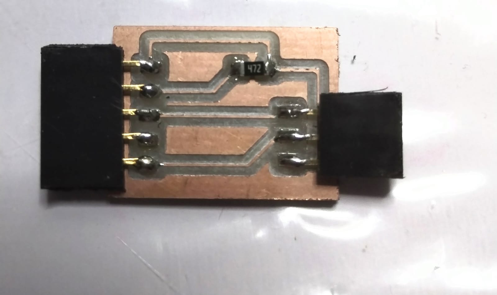 |
Documents
- One servomotor
- Two servomotors
- Servomotor with a potenciomenter
- Printing text with an Oled
- Printing drawings with an Oled
- Controlling a potenciomenter and show it on the Oled
- PCB of the new design
- Schematic of the new design