Electronics Production
Group assignment
- Characterize the design rules for your in-house PCB production process: document feeds, speeds, plunge rate, depth of cut (traces and outline) and tooling.
- Document the workflow for sending a PCB to a board house.
- Document your work to the group work page and reflect on your individual page what you learned
In our group assigment you can see all the things we did for the practice, nevertheless I wanted to put some brief points that I learned from it:
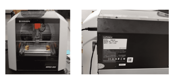
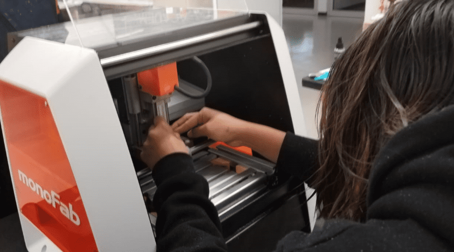
- The machine I used for this practice was the "ROLAND SRM-20", which has the same bases of functioning as the other two machines (MDX-20 and Lunyee) shown on the group assigment.
- The Mini Mills work as a CNC, so it has front cover (protective shield), power button (turn it on or off), spindle head (where the too is mounted) and the working table (surfece where the PCB material is secured).
- It has a varied compatible material list, for example: modeling wax, chemical wood, foam, acrylic,acrylonitrile, HDPE, wood, polycarbonate and PCBs.
- Some safety guidelines: The machine should be operated by one person at a time, you shouldn't put you hands over the cutting area while working, in case of malfuctioning, switch off the machine, do not allow metals or liquids, you should use a brush to clean metal savings,or a vacuum cleaner, among others.
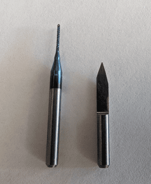
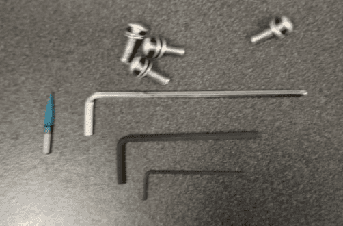
- There were used two tools. For engraving it was a used a 15 degree V-bit and for cutting we are using a 0.8 mm diameter two flute end Mill.

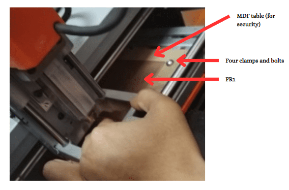
- For the milling purposes we are using a FR1 because it is a softer material and it's dust is less toxic.
Individual assignment
After learning all the basics of the machine, I needed to make and test a microcontrolled development board.
Toolpath
The first step to perform is to enter the webpage in which we can generate the documents to be uploaded to the machine interface. The link is the following :Modsproject
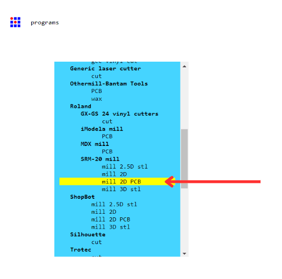
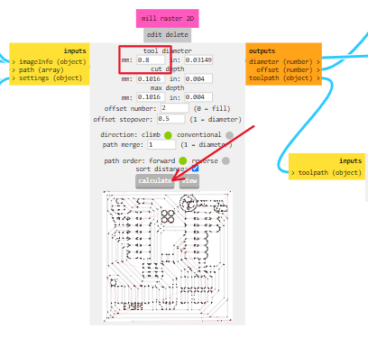
We need to select the machine, which is the Mill 2D PCB, in order to choose the correct parameters.
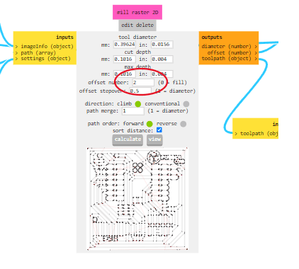
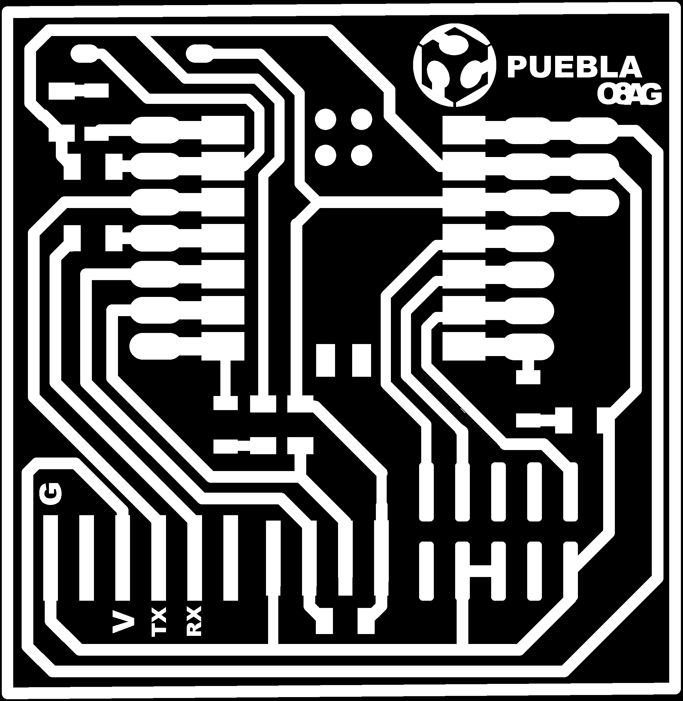
Traces
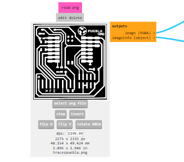
- Place the image of the corresponding traces to cut them on the copper board.
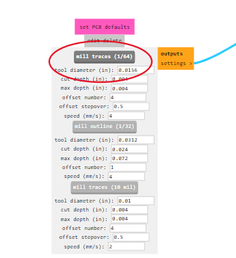
- In this section, we need to select the following:
- Once this section is selected, the parameters of the tool are changed.
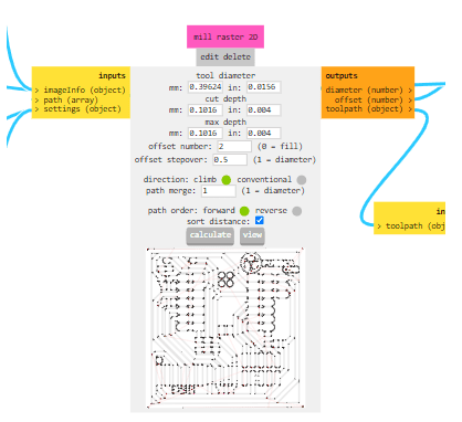
- An offset of 2 must be applied, as multiple practical tests with the equipment have demonstrated that it is the most appropriate.
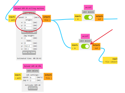
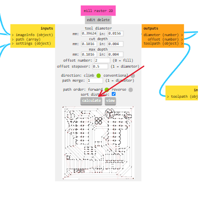
- In the section of the Roland SRM-20 milling machine, the origins must be set to 0 to correctly interpret the parameters for the machine.You enable this section so when you click "calculate" the rml document is document.
- Click the "calculate", once this is done, an RML document is generated to be entered into the program.

Cuts
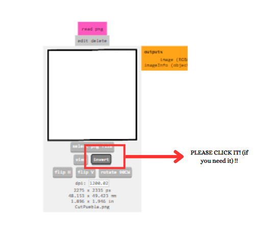
- First, the corresponding image (in this case, a PNG) needs to be changed, and the image must be inverted.
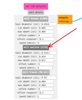
- Instead of selecting "mill tracers," choose "mill outline."
- Once this is done, change the "tool diameter" to the diameter of the tool to be used, which in this case is 0.8. After this, just click "calculate". Create the rml document.

Milled and stuffed the board
- Ensure that the ROLAND SRM-20 is placed on a stable and flat surface.
- Connect the machine to a power source and turn it on.
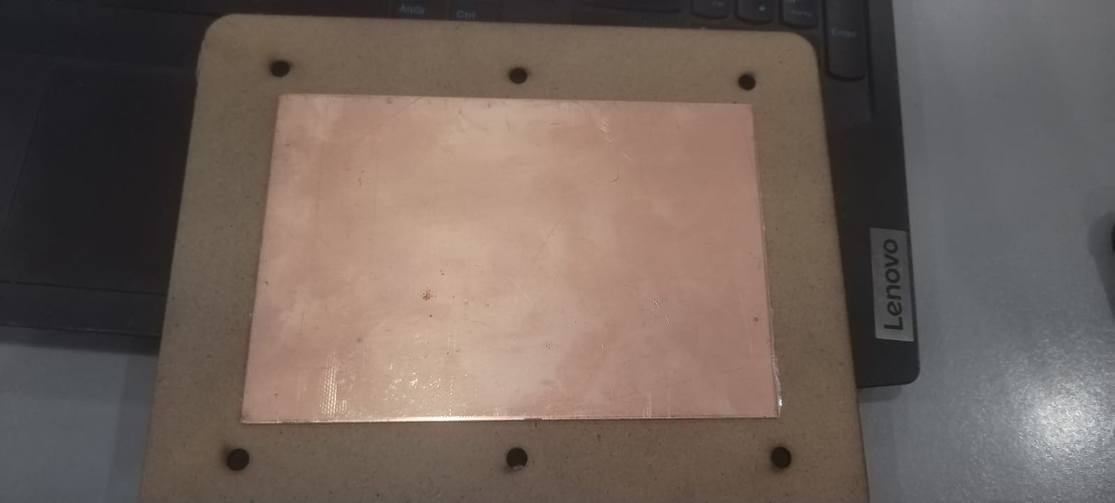
- Secure the material(in this case the pcb material) onto the milling bed using clamps.
- First it was used the 15 degree V-bit to do the traces.
- Install the tool into the spindle collet, following the manufacturer's guidelines.Please make sure the tool is securely tightened.Here are the tools used to change the tool:
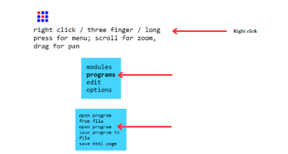
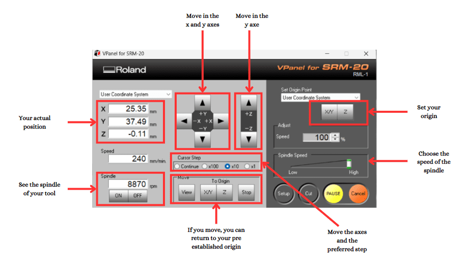
- Open the software VPanel for the ROLAND SRM-20, it looks something like this:
- Set the origin point on your material where the milling process will begin.
- Use the software to define the starting point, taking into account the dimensions and features of your design.
- Calibrate the machine by homing the axes and ensuring that the tool is correctly positioned above the material.
- After you colocated the axes, you spindle the tool, and lower the z axe -0.1 so it actually works.
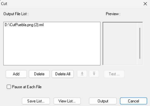
- Then you click the section "cut" in order to upload the rml document prevously created. It should appear something like this:
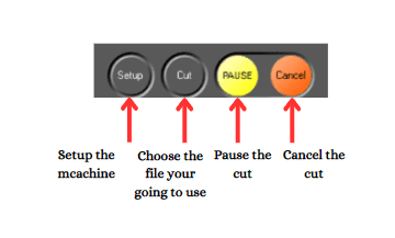
- There if there is any document already uploaded, you should click "Delete all" and after that, you should click "Add" and choose the file you want to cut or trace.
- Then you click "Output" and the machine will start working.
Solding
- 1 XIA0-RP2040
- 3 resistances of 1KΩ
- 1 resistance of 2KΩ
- 3 superficial LEDs
- 1 button
- 1 row of pins
Materials
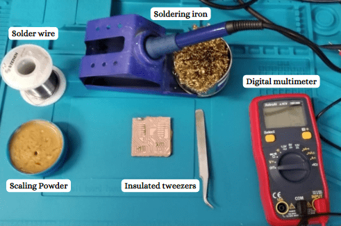
- Prepare your area with the necessary materials:
- Prepare the Work Area: ensure good ventilation, place the components on a heat-resistant surface and keep any flammable materials away.
- Ensure they are clean and free of contaminants.
- Melt a small amount of solder onto the tip of the soldering iron. This is known as tinning and helps with heat transfer.
- Place the components to be soldered in their correct positions, ensuring a secure fit.
- Touch the soldering iron to the joint where the component lead meets the circuit board pad.
- Heat the joint for a few seconds to ensure it's hot enough to melt the solder.
- Touch the solder wire to the joint, not the soldering iron.
- Allow the solder to melt and flow evenly around the joint.
- Allow the solder to cool and solidify before moving the components.
- Examine the solder joint for a smooth, shiny appearance. A dull or grainy look may indicate a cold joint.
- Repeat the process for all the solder joints, working methodically through the components.
- Clean the soldering iron tip again before moving to the next joint.
- Once all soldering is complete, turn off the soldering iron and allow it to cool down.
Steps
Code and function
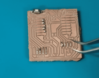
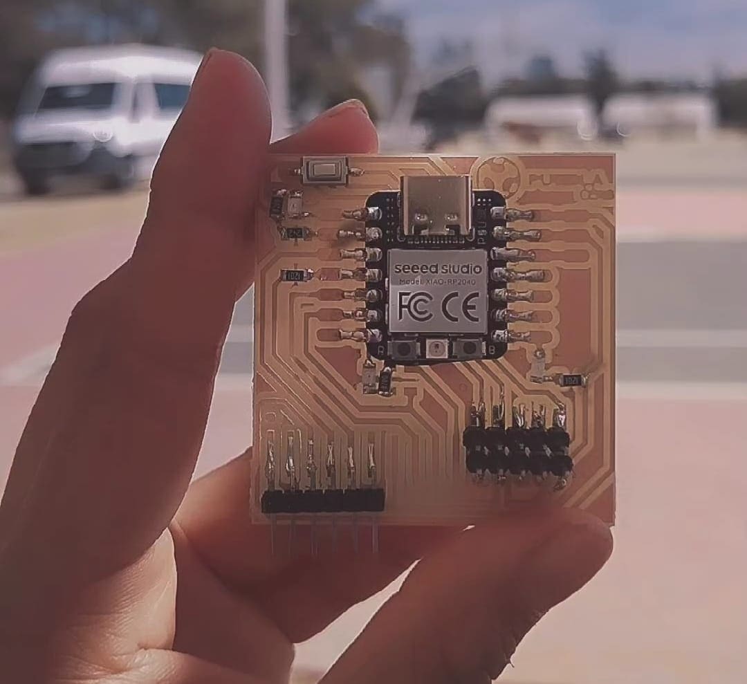
- First, I had to connect it and chek al least the LEDs of the microcontroller functions correctly, as the image shown below:

- Arduino is an open-source electronics platform that consists of both hardware and software components.
- Download Arduino from: Arduino webpage
- Open Arduino
- I started coding so I can check that the microcontroller works properly.
- This Arduino code consists of two main functions: setup() and loop(). In the setup() function, certain pins on the Arduino board are configured - pin D1 is set as an input, while pins 26, D7, and D6 are set as outputs. he loop() function then continuously executes a sequence. It reads the digital state of pin D1 and mirrors that state to pin 26, effectively syncing them. Additionally, it turns on LEDs connected to pins D6 and D7, waits for one second, turns them off, and repeats the process, creating a blinking effect. The intended behavior is to have the LED on pin D1 control the state of pin 26, while pins D6 and D7 blink alternately:
- After compilation, I could check the fact that the all the components fuction correctly:
Problems and how I solved them
Not inverting the image
The first time I cut the PCB, I didn't inverted the image of the cut, so the machine cut my voltage trace.
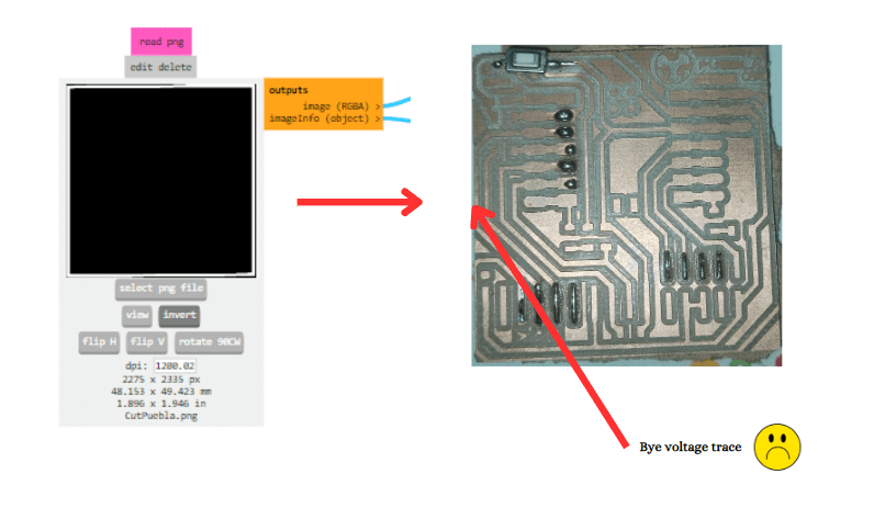
I solved it by just generating a new rml document on the page by inverting the image.
Not calibrating the machine correctly
Disclaimer: I didn't took amazing photos here, bacause I was panicking :0
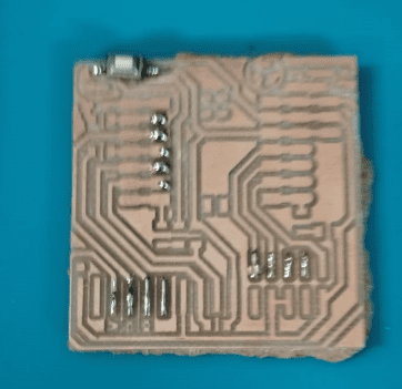
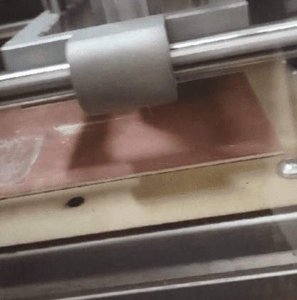
I didn't calibrate the z axe correctly two times. The first time it barely cut it, because it didn't touch the PCB material correctly (the z-axe wasn't calibrated correctly), it looked something like this:
The second time I couldn't calibrate correctly again the z-axe, it was because it was taking too much material, so the traces were practically distroyed.
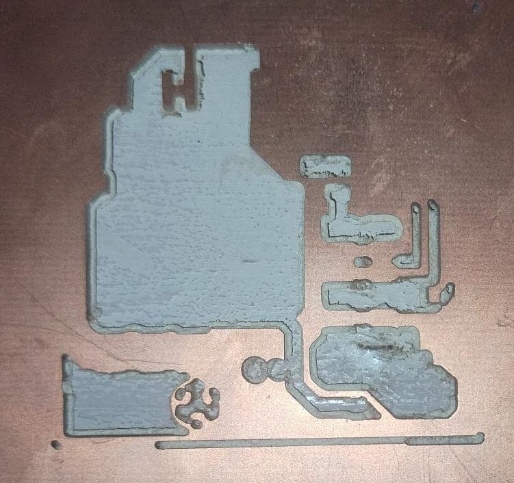
I solved it by placing a post-it note at the base and lowering the Z-axis until it touched the post-it and prevented it from coming out. Once this was done, I would turn on the tool and lower it, micrometer by micrometer, until I noticed that it was cutting into the material slightly. I would then set that value as my new Z-axis position.
Solding
I didn't had any problems while solding the PCB, but I recommend you to put your favorite playlist and take at least one hour of concentration so you don't burn anything and everything solds perfectly.
In case you were wondering, I was listening to this :) and everything turned perfectly.
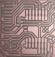
Final result
Documents
- Cut rml document
- Traces png image
- Traces rml document
- Traces png image
- Code Arduino for the microcontroller