
Embedded Programming made in 🎀pink🎀
Hey there guuuuurl, welcome to this week's assignment where we're diving into the world of super fun Arduino and Python programming yaaaaay🧸
Okay, so let me break it down for you in girl pink terms hun 💅🏼 so we are in the same page. Let's start with the basics: the syntax rules. We'll be comparing Python and C++ because, why not? lol
Python makes life easy. You just throw in a value, and Python figures out the rest. No need to sweat about declaring types! Check its syntax:
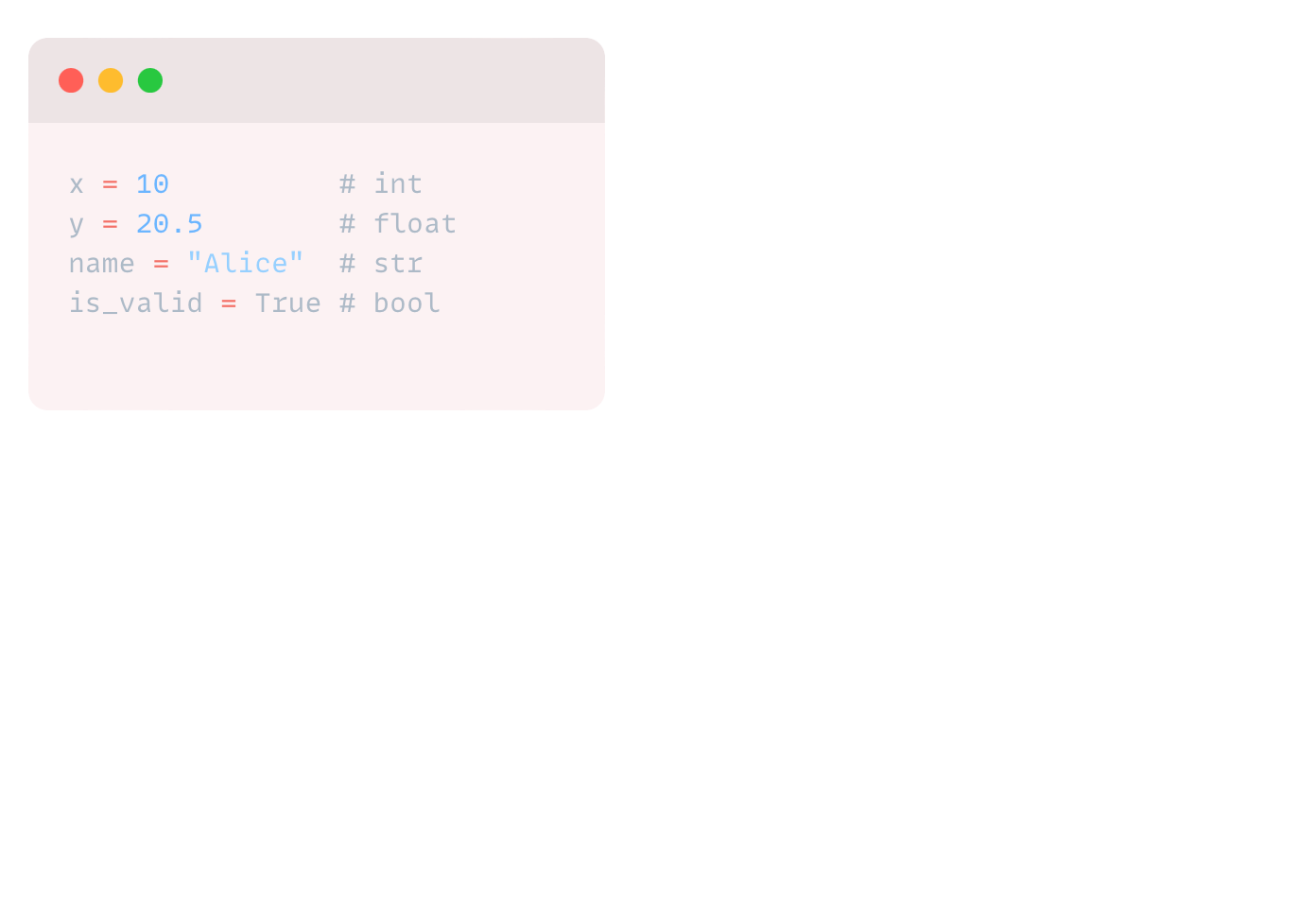
TO KNOW MORE GO HERE-->
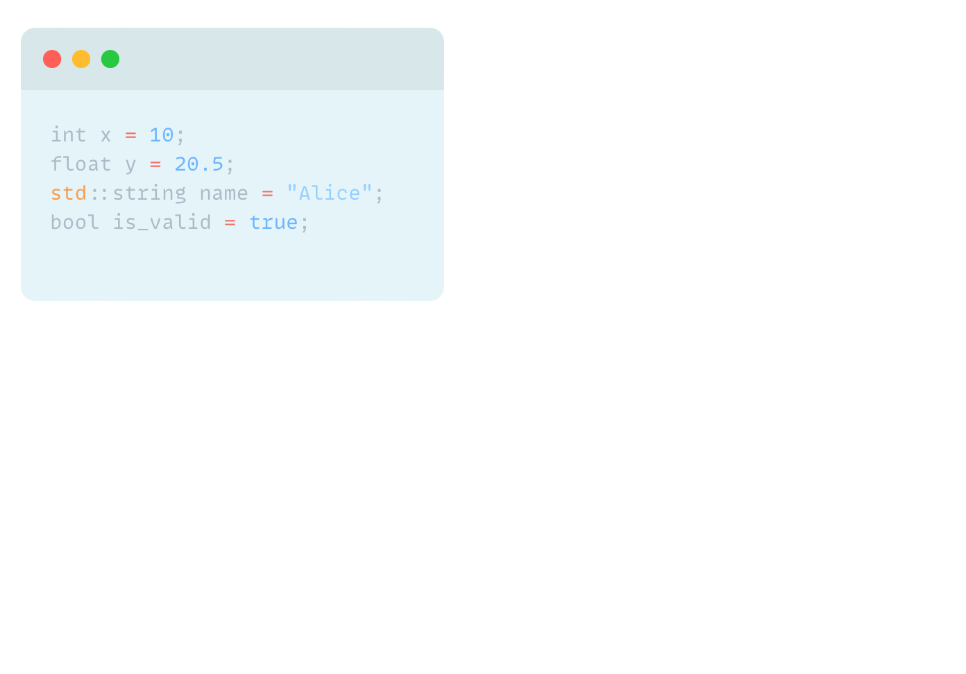
Now, C++ is a bit more formal. You gotta tell it what type of data you're dealing with upfront:
Alright, so let’s talk about the 🐘 in the room guys… programming in Python versus Arduino, which language is BETTER??
Python runs on an interpreter, so it's pretty straightforward and portable across different systems. This means that every single line of code you do will be read from begging to end as a single line command, so the symptoms will be a little to none perceived delay in your devices which still sounds good to me right?
Anyways if you do not feel very comfortable with this or you are programming something the old-fashioned way then Arduino is this open-source hardware prototyping platform that's a compiling code type. This means that your code will be read as an embedded package.
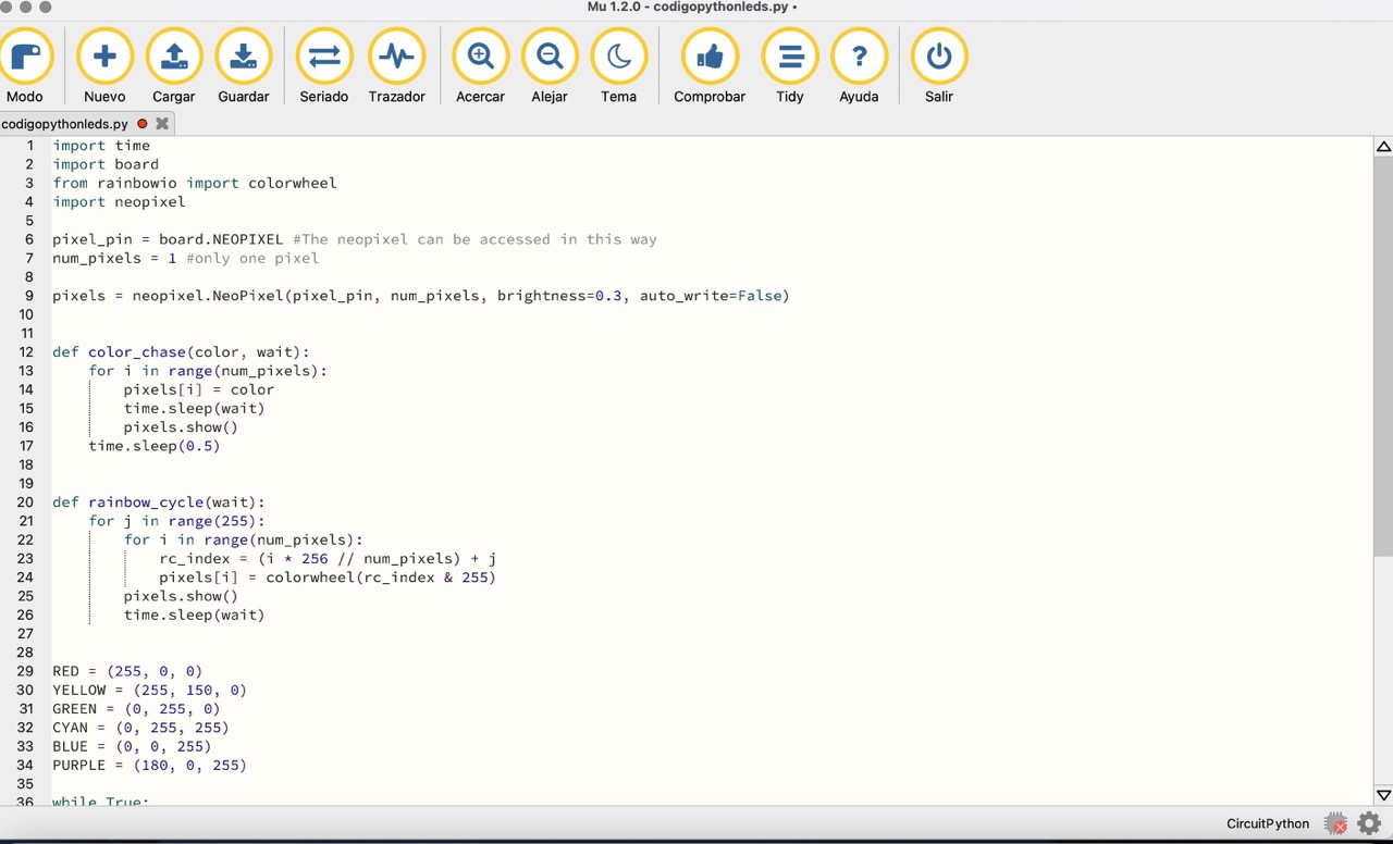
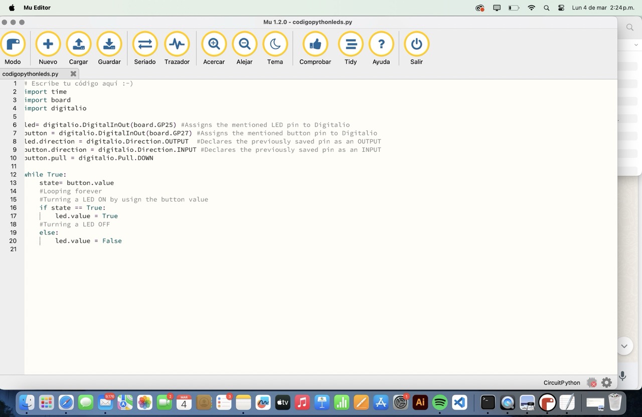
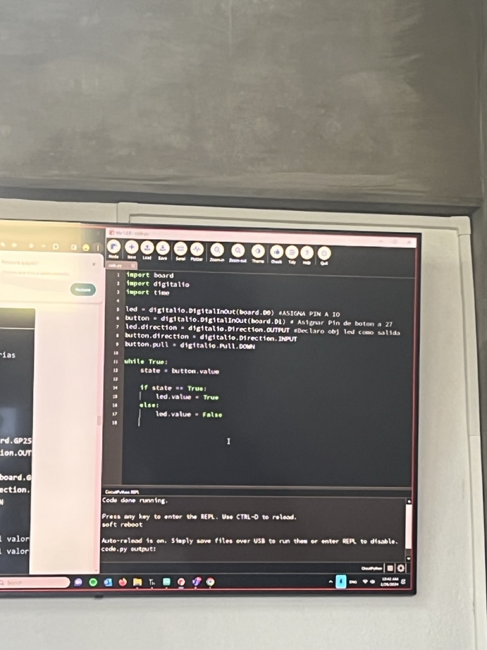
I programmed the RGB led that is in my XIAO so it changed colors with a simple delay, very rainbow 🌈 ish lol. For this I imported a universal library to my laptop and downloaded the ones that said: Neopixel and Adafruit_pixelbuf so I could call them from my MU code editor.
- TO SEE AND KNOW ALL ABOUT THIS XIAO BOARD I MADE AT WEEK 4 CLICK HERE
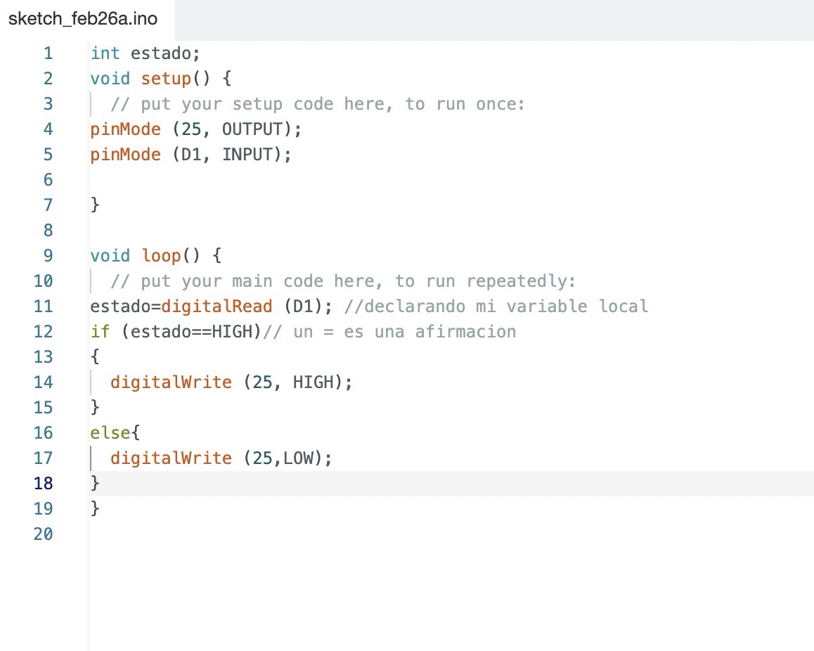
This cute little code for our adorable Xiao board makes some shiny LEDs light up in a fun way! 🌟 When you first turn on the board, it sets up some pins to be either input or output. Think of pin D1 as our "sensing pin," and pins 26, D7, and D6 as our "glam pins" for the LEDs.
In the setup, our glam pins get ready to shine. Then, in the loop (which runs forever like the best dance party ever yay), the code checks if pin D1 is high or low and makes pin 26 follow along. It turns on the LEDs on D6 and D7, making them sparkle for 1 second.
Then, it turns them off for another second, repeating this sparkle-off, sparkle-on routine forever. So, it’s like your Xiao board is putting on the cutest light show, with pin 26 mirroring the mood of pin D1! ✨
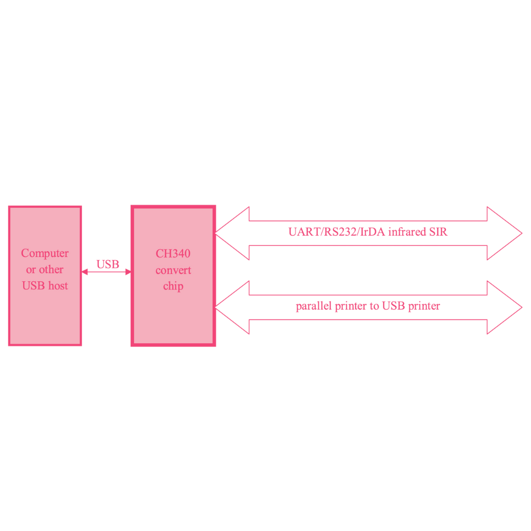
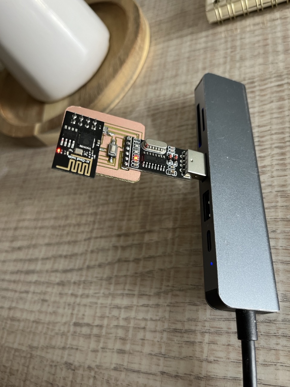
When you plug your programming board into your computer's USB port, the CH340 chip acts like a translator between your computer and the ESP8266. It converts USB signals to serial signals that the ESP8266 can understand.
The CH340 supplies power to your ESP8266. The VCC pin on the CH340 connects to the 3.3V input on the ESP8266, powering it up. Ground (GND) is also connected between both to complete the circuit.
- CLICK HERE TO SEE EVERY DETAIL OF HOW THIS BOARD WORKED *networking and coms week*
🐝TXD (Transmit Data): This pin on the CH340 sends data from the computer to the ESP8266. It connects to the RX (Receive) pin on the ESP8266.
🐝RXD (Receive Data): This pin on the CH340 receives data from the ESP8266 and sends it to the computer. It connects to the TX (Transmit) pin on the ESP8266.
🐝The DTR (Data Terminal Ready) pin on the CH340 is connected to the reset (RST) pin on the ESP8266 through a small capacitor. This connection allows the computer to reset the ESP8266 automatically, putting it into programming mode without you having to press any buttons manually.
🐝Additionally, a button connected between GPIO0 and GND is used to manually put the ESP8266 into programming mode when needed.
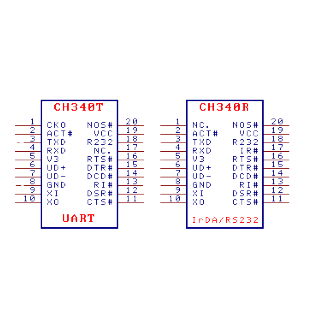
Grab the CH340 Datasheet ---> Identify key pins ---> VCC, GND, TXD, RXD, DTR.
- CH340 DATA SHEET
Design the Schematic ---> Connect CH340 to ESP8266👇🏽
VCC to 3.3V
GND to GND
TXD to RX
RXD to TX
DTR to RST through a 0.1µF capacitor, GPIO0 to GND via a button.
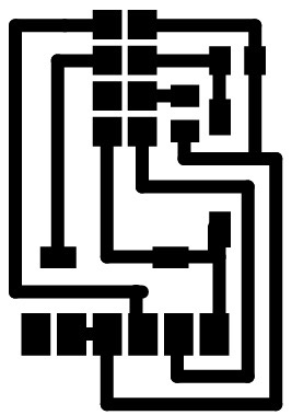
Design the PCB: Place components, route traces, export Gerber files, and mill the PCB.
Assemble Your Board: Solder CH340, headers, and components, check connections.
Install CH340 Driver: So your computer recognizes the USB to TTL converter.
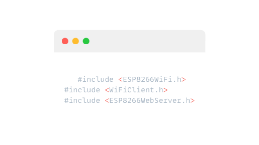
First you´ll need to include the required libraries at the beginning of your code
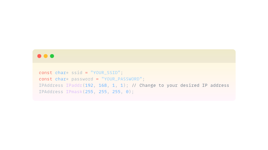
Then u need 2 define WiFi credentials and IP configuration
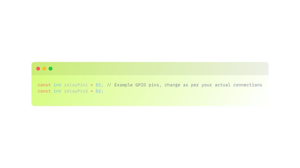
After define GPIO pins connected to relay modules
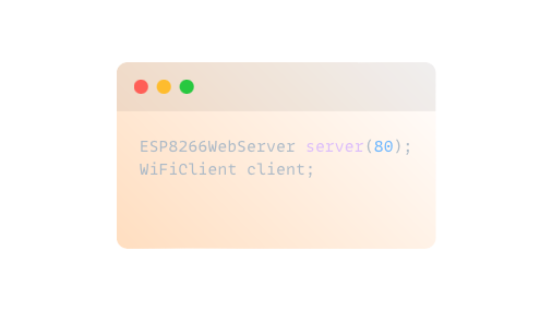
Initialize the ESP8266WebServer and WiFiClient objects
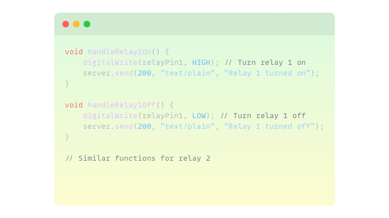
Create functions to handle turning relays on and off based on web requests
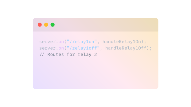
Define routes for controlling relays via HTTP requests
Set GPIO pins as outputs and connect to WiFi network
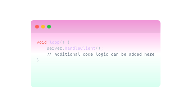
 Implement the loop function to handle incoming cute client requests
And finally compile and upload the code to your ESP8266 via the Arduino IDE. Connect your 5V relay modules and lamp to the GPIO pins as per your circuit design. Access the ESP8266's IP address in a web browser to control the relays and verify lamp operation.
- CLICK HERE TO SEE EVERY DETAIL OF HOW THIS BOARD WORKED *networking and coms week*
- CLICK HERE TO SEE EVERY DETAIL OF HOW THIS BOARD WORKED *interface*
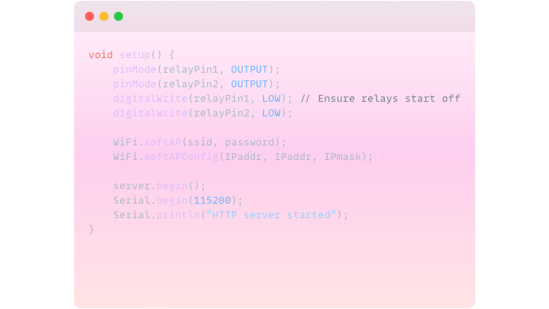
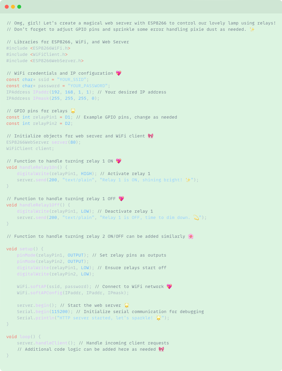
Libraries: Importing necessary libraries for ESP8266, WiFi, and web server functionalities.
Constants and Variables: Defining WiFi credentials, IP configurations, and GPIO pins for relay control.
Setup Function: Configuring GPIO pins, setting up WiFi access point, starting the web server, and initializing serial communication for debugging.
Loop Function: Continuously handles incoming client requests to control relays through HTTP requests.
Functions: handleRelay1On() and handleRelay1Off() manage turning the first relay on and off respectively, sending cute messages back to the client.
So programming in Python is super chill, easy-to-read language (or so I’ve been told) used for all sorts of stuff like web development, data analysis, etc…
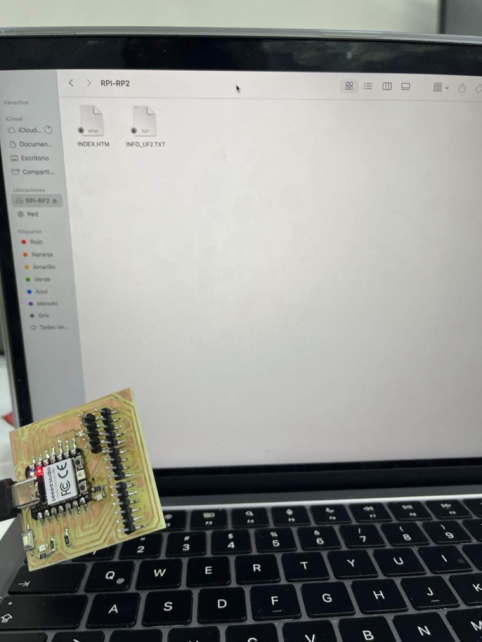
It's got its own simplified version of C/C++ for coding, which is perfect for controlling sensors, lights, and all that electronic cute stuff awww My personal opinion (because I prefer Arduino) it’s that if you're aaaaaaall into hardware projects, Arduino is where it's at, this is because of its origin of embedding the code and processing it faster to your components. For this week’s assignment I decided to program my board with a print which shows me the distance an object is between my cute ultrasonic sensor and it. First I had to test my board and plate with another code to see if it would totally run or if I actually did ruined it all… I decided to try Python first because I already knew how to use Arduino and this Fab Lab is totally about taking risks and trying something new.
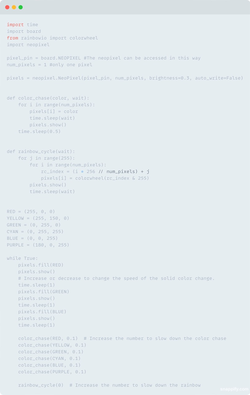
After I made some tests playing with the Red Green Blue values I decided that it was time to start the programming of my assignment in Arduino. Here you can see the difference between both languajes, it´s the same code, it did the same but each one in a different languaje.
Now my super personal opinion about all this
Okay, so Python is like that comfy, cozy sweater you wear on a lazy Sunday. It’s super easy to slip on, and you feel all warm and fuzzy because it’s simple and straightforward. But let me tell you, C++ is like the stunning, designer dress you put on when you want to make a statement and feel absolutely fabulous! YES. I ABSOLUTELY LOVE C++. C++ lets you get up close and personal with your hardware, which is just so thrilling! You have all this control, and you can make everything so efficient and fast. And the best part? You get to manage memory and use pointers, which might sound geeky but is actually super empowering. It’s like knowing all the secret hacks to make your program run like bu tt er. Sure, Python is great for quick and easy tasks, but C++ is where you really get to shine and show off your skills. It’s powerful, elegant, and so sophisticated. So, while I’ll always have a soft spot for Python, C++ will forever be my coding crush! 💖👩💻✨
Amazing sweetie and what did u do for this task?
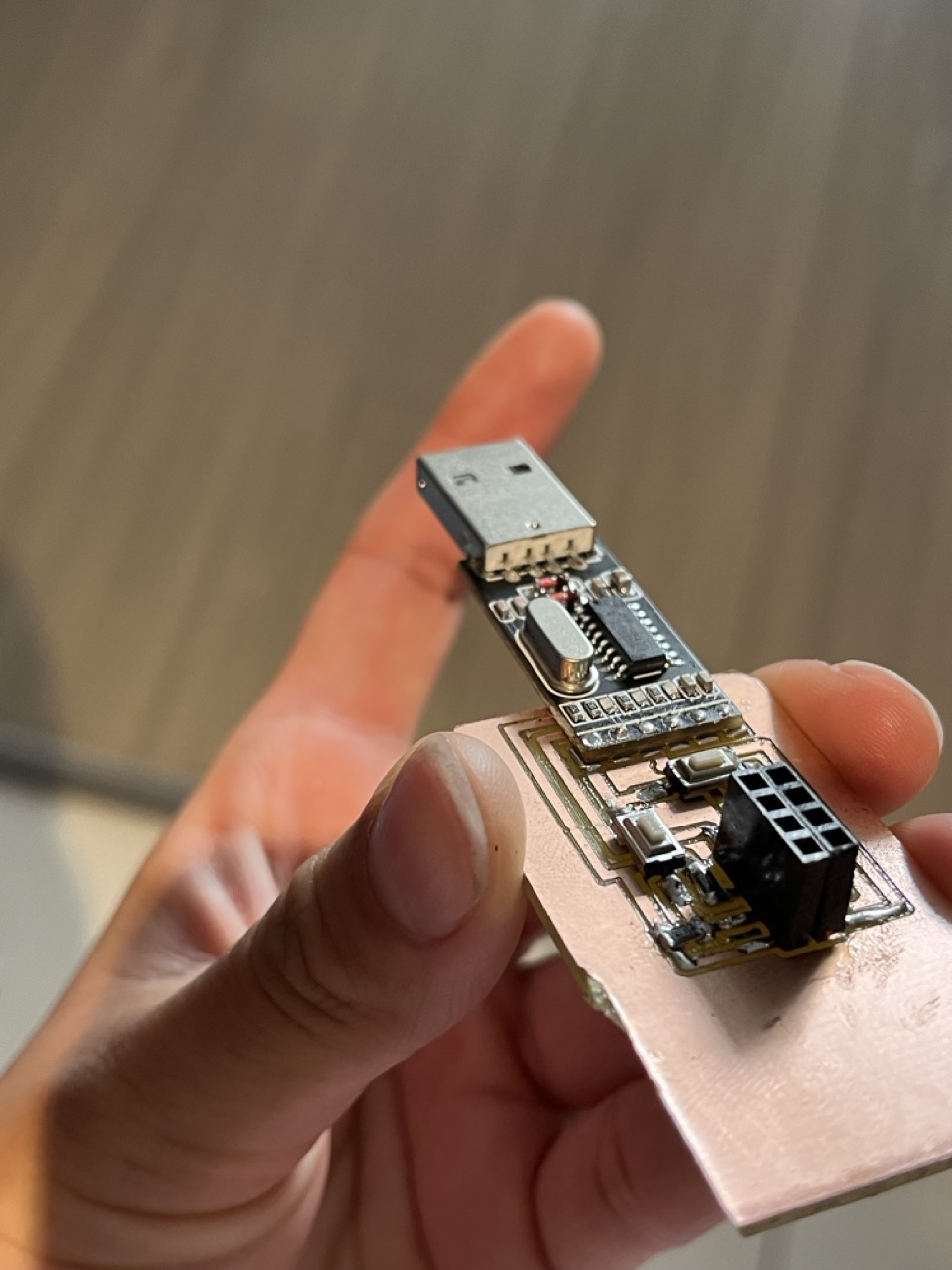
Okay girl so, I´ve been planing for week 13 to make a programming plug that programms my esp8266 12-f of my final project, in this case obviously I will mill my board and weld it all together. In this situation I´ll need a code honey bee, and I will use this assignment to advance the coding part!!!! OMG so excited!!!!
So, this super cute programming plug with the CH340 makes it super easy to upload code to your ESP8266. It powers the ESP8266, handles data transmission, and even resets the ESP8266 automatically for programming. With this setup, you can effortlessly program your ESP8266 for your final project. You’re all set to shine, honey bee! 💖✨
So let´s go!
We're using the amazing ESP8266 with its WiFi magic to create a web server. It's like a little digital princess castle that controls these darling relays, which in turn control your stunning 5V lamp! Make sure to customize the GPIO pins and add some error fairy dust as needed. Once it's all set up, you'll have the most stylish and functional setup ever! You can light up your fabulous lamp with just a few magical clicks on your web browser! It's like bringing a touch of sparkle and glam to your tech world! 🌟💡 Shine bright like a diamond
How it works?
All about the data transmission
So now for the frankeistein creation
How I did it?
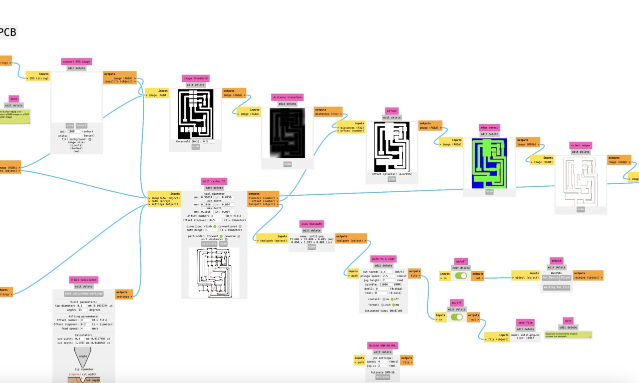
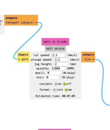
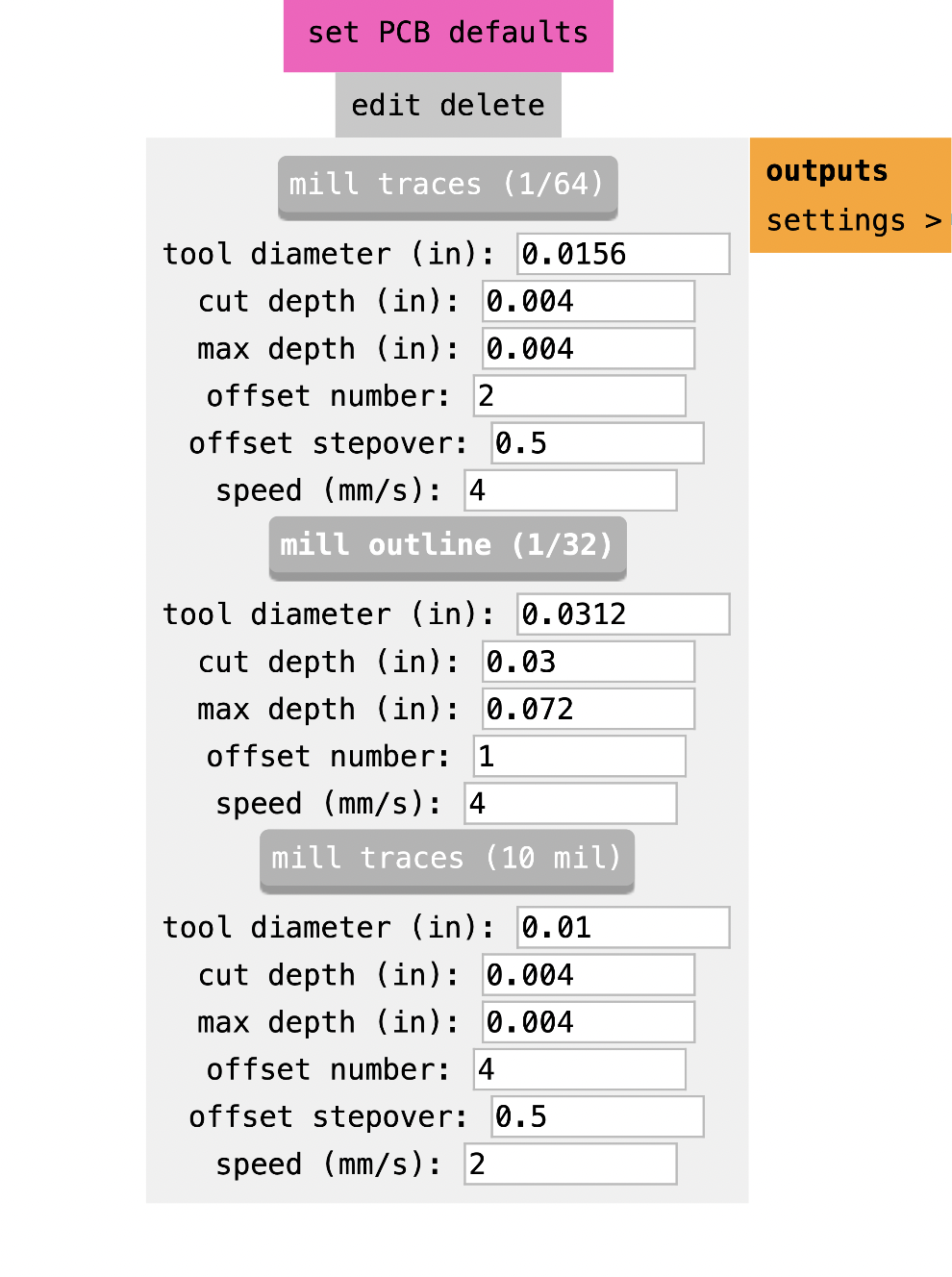
So for the electronic design software I used PCB wizard cuz honestly I don´t like at all KiCad, for me it was so much easier to draw what I wanted for the components disposure and to draw lines between them so I understood it better. I used the Roland SRM for the milling process and used obviously MODS for the programming, Vcarve for the cutting process software, but you can see the pics and parameters on the electronic design week, I really prefer that you´ll totally embed your attention in the programming and all this Data for this week hun.
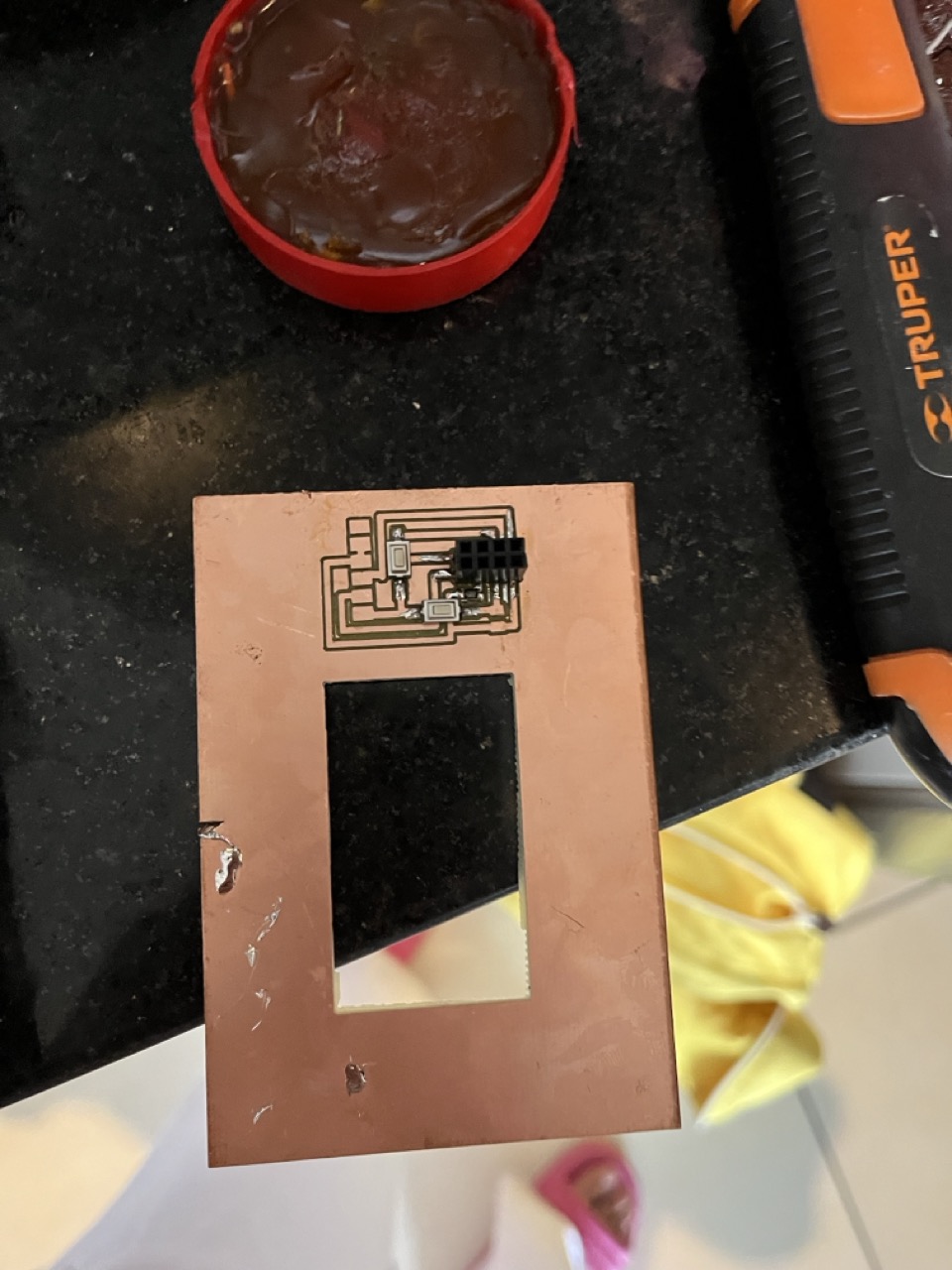
I´ll give you a little sneak peek here:
And all about the assembly you´ll need to solder the CH340, headers, and supporting components (resistors, capacitors). Then check connections and ensure all connections are solid and there are no shorts.
So for the programming
First you´ll need to connect the board, plug your programming board into the USB port of your computer. The CH340 will handle the communication setup. Also you´ll need the driver installation, make sure you ensure the CH340 driver is installed on your computer so it can recognize the converter.
As I was saying you’ll need the Arduino IDE to program your ESP8266. Install the CH340 driver on your computer so it can recognize the USB to TTL converter. Then, write your code in the Arduino IDE, select the correct board (ESP8266), and the right COM port.
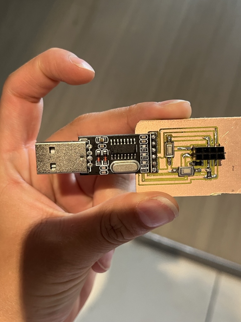
My hard work pics📸
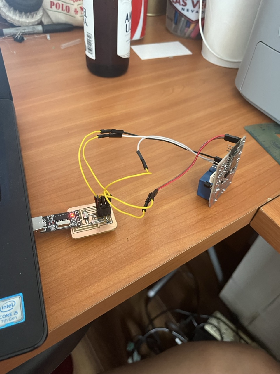
AND HERE TO KNOW ALL ABOUT THE PROGRAMMING APPS FOR MY BOARD-->
It ended looking and working amazingly, if you wanna know all about the complete circuit with the rele board feel free to go to networking an comunications week.
And the cheat sheet this week gurl? Imma need it
Of course girl here it is:
ALL ABOUT.....
To see how it ended and looked like feel free to stay tuned for networking and communication´s week