✨NETWORKING & COMMUNICATION✨
Hey there sis, welcome to this week's assignment where we were challenged to make communications and networking protocols between 2 boards.
Okay, so here´s the deal dude, tbh I didn´t knew how to do any of this before this asignment, I studied the protocols and all I learned was this:
So darling, electronic communication protocols are like the latest trends in fashion for your devices! From UART’s sleek simplicity to USB’s versatile glam, each protocol adds its own flair. Whether it's SPI’s high-speed charm or Bluetooth’s wireless elegance, these protocols ensure your tech communicates flawlessly. Ethernet brings the runway to local networks, while Zigbee shines in smart homes. With MQTT’s lightweight finesse and Modbus’s industrial chic, these protocols keep your devices connected with style and sophistication. Embrace them to ensure your gadgets are always in vogue! 💖✨📡
UART, or Universal Asynchronous Receiver/Transmitter, is like the glamorous interpreter between your computer and the ESP8266 microcontroller on your relay board. It translates data into signals that the microcontroller can understand and vice versa. Think of it as the sophisticated translator at a high-end fashion show.Get ready for some really cool COMMUNICATION✨stuff ahead lol.
Our group weekly task ---->
FROM NOW ON TILL THIS PAGE ENDS THIS IS ALL WE´VE TALKED ABOUT AND WHAT YOU´LL NEED TO KNOW...
UART (Universal Asynchronous Receiver/Transmitter) A simple, serial communication protocol that doesn’t need a clock signal. ❤︎Use Cases→ Perfect for microcontroller programming and serial communication between computers and peripherals. ❤︎Advantages→ Easy to use with a low pin count. ❤︎Disadvantages→ Slower data rates and no error checking.
I2C (Inter-Integrated Circuit) A fabulous multi-master, multi-slave, packet-switched, single-ended, serial communication bus. ❤︎Use Cases→ Connecting sensors, RTCs, and other peripherals to microcontrollers. ❤︎Advantages→ Multiple devices on a single bus with just two wires (SDA and SCL). ❤︎Disadvantages→ Limited to short distances and slower compared to SPI.
SPI (Serial Peripheral Interface) A synchronous serial communication protocol for short-distance, high-speed communication. ❤︎Use Cases→ Communicating with sensors, SD cards, and displays in style. ❤︎Advantages→ High speed and simple hardware connections. ❤︎Disadvantages→ Requires more pins and not ideal for multiple slaves without extra hardware.
CAN (Controller Area Network) A robust protocol perfect for vehicles, allowing microcontrollers to chat without a host computer. ❤︎Use Cases→ Automotive and industrial applications where reliability is key. ❤︎Advantages→ Highly reliable with error detection. ❤︎Disadvantages→ More complex to set up and requires more wiring.
Wi-Fi (Wireless Fidelity) The fabulous family of wireless network protocols for broad connectivity. ❤︎Use Cases→ Internet and network connectivity for computers, smartphones, and IoT devices. ❤︎Advantages→ High data rates and broad range. ❤︎Disadvantages→ Higher power consumption and potential interference.
Ethernet The chic standard for wired networking in local, metropolitan, and wide area networks. ❤︎Use Cases→ Networking computers and devices in a LAN. ❤︎Advantages→ High speed and supports long distances. ❤︎Disadvantages→ Requires more hardware and a complex setup.
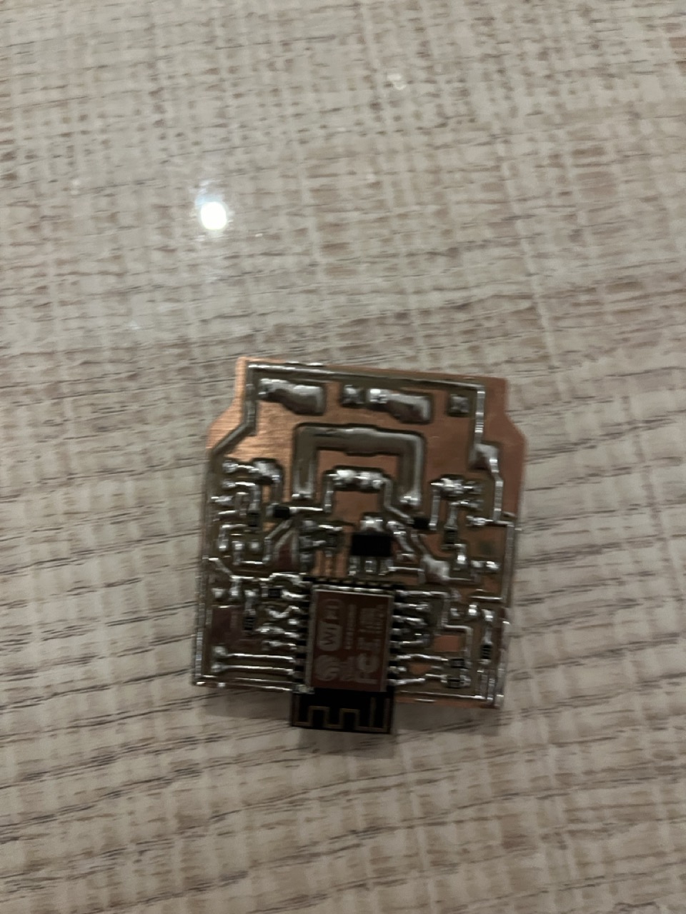
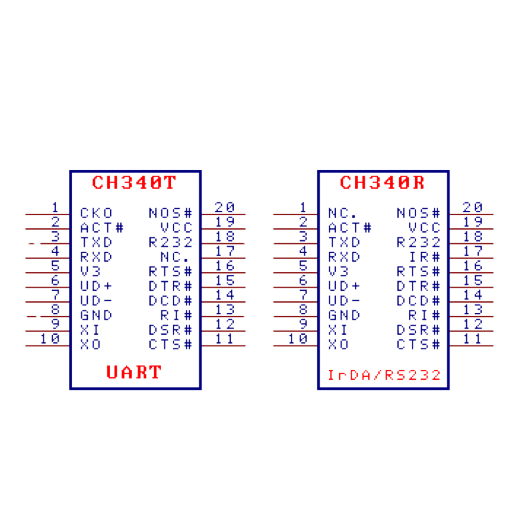
Darling, now let me paint you a picture of how our glamorous UART protocol connects my fabulous CH340 plug to the dazzling ESP8266 relay board (and how I program the ESP of all my projects from here)
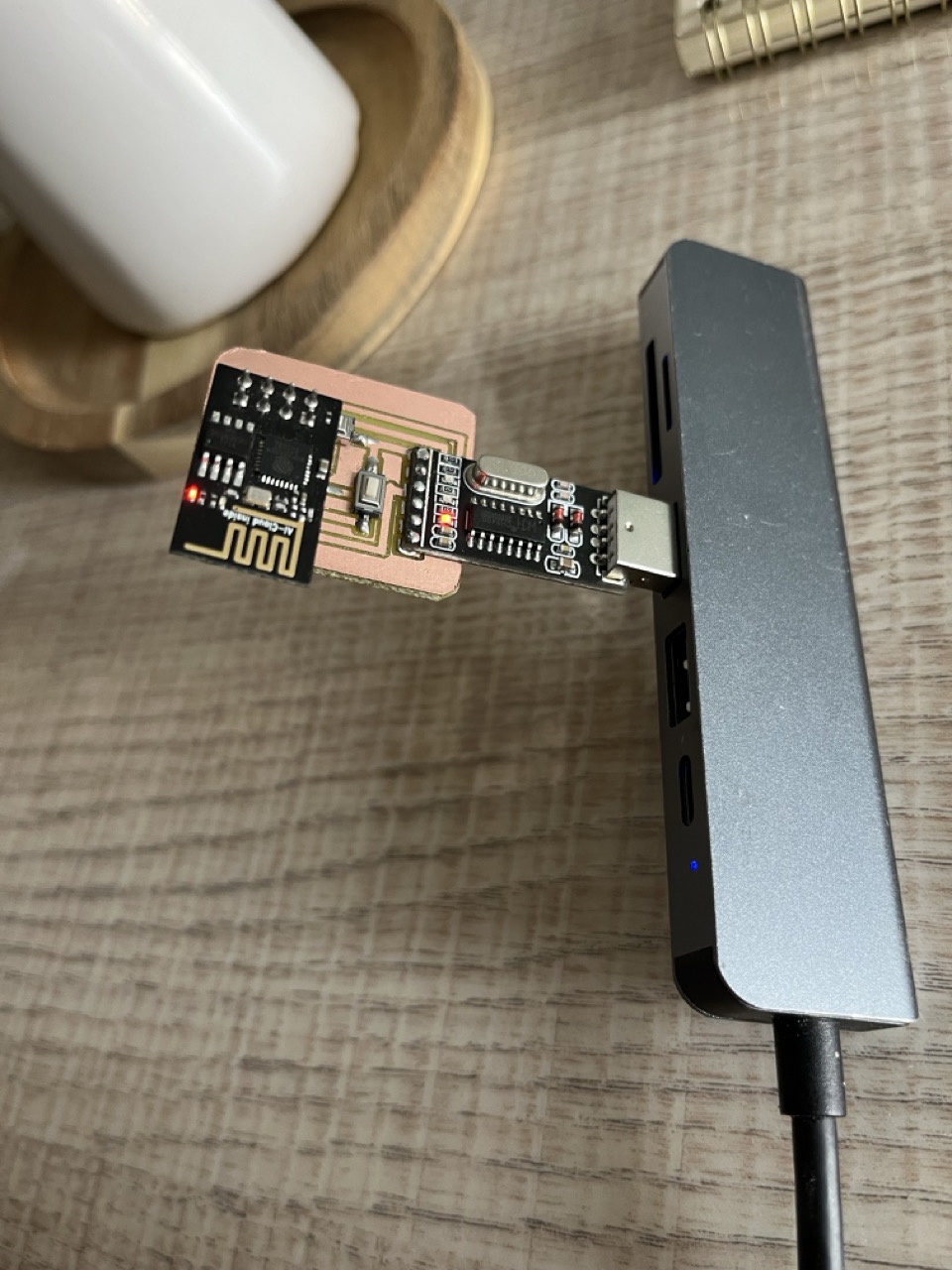
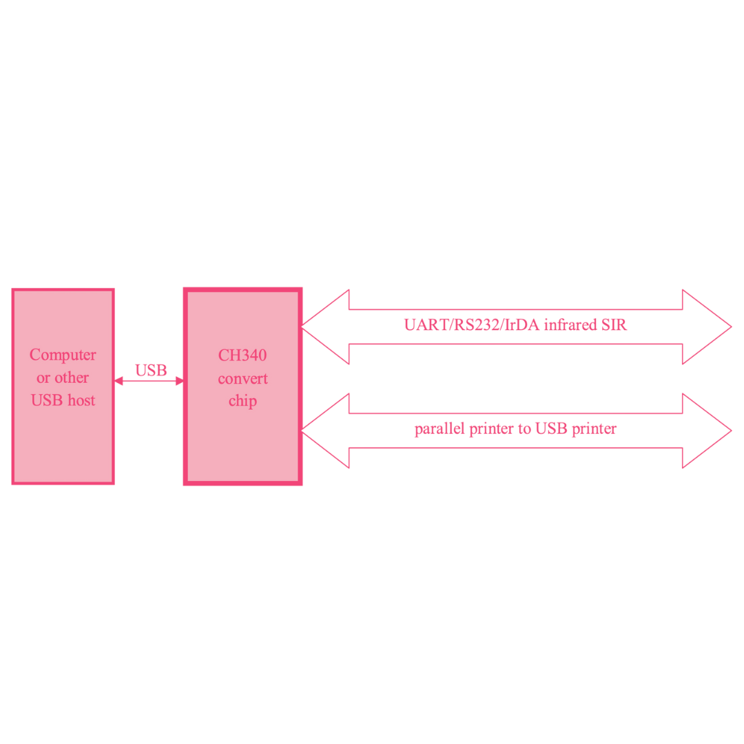
The CH340 acts as a bridge between your computer (via USB) and the ESP8266 microcontroller, so when you upload code or send commands from your computer, the CH340 converts these signals into UART serial data. This data is transmitted (TX) to the ESP8266, which receives (RX) and processes it similarly, responses or data from the ESP8266 are transmitted back to the CH340 via UART, then the CH340 then converts this data back into a format understandable by your computer. IN A NUTSHELL----> The UART protocol allows for bidirectional communication, enabling you to program the ESP8266 and control the relay board remotely. It's essential for uploading code, debugging, and sending/receiving data between your computer and the ESP8266 board. Ensure baud rate settings (typically 115200 or 9600 bps) are consistent between the CH340 and ESP8266 for reliable communication.
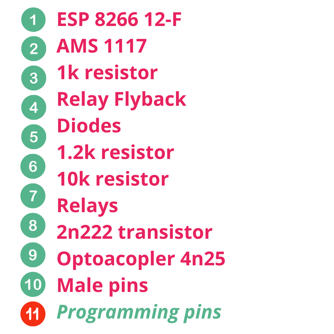
My gorgeous table of components for the ESP-12-F BOARD
SOPHIE´S RELAYS ESP BOARD🎀 |
Where to buy? | Amount | Price | Total price |
| Relevador 5V DC SRD-5VDC-SL-C | UNIT electronics | 2 | $15.00 MXN/unit | $30.00 MXN |
| AMS1117 3.3V | Digikey | 1 | $12.80 MXN/unit | $12.80 MXN |
| 1.2 k capacitor 122 | Amazon | 2 | $122.00 MXN/unit | $1.00 MXN |
| ESP-12-F | Mercado Libre | 1 | $90.00 MXN/unit | $90 MXN |
| 1k resistor 1001 | Mouser Electronics | 2 | $1.14 MXN/unit | $2.24 MXN |
| 10k resistor 1002 | Mouser Electronics | 4 | 1.60 MXN/unit | $6.40 MXN |
| Diodes | Mouser electronics | 2 | $0.25 MXN/unit | $0.50 MXN |
| transistor 2n2222 | Tostatronic | 2 | $2.00 MXN/unit | $4.00 MXN |
| Male pins | Tostatronic | 2 | $7.00 MXN/unit | $14.00 MXN | Optoacoplador 4n25 | Tostatronic | 2 | $16.95 MXN/unit | $5.00 MXN |
| Total cost | $165.94 MXN |
SOPHIE´S PLUG DEVICE🌺 |
Where to buy? | Amount | Price | Total price |
| CH340 USB TO TTL | Ali express | 1 | $20.76 MXN/unit | $20.76 MXN |
| Female 2 row header pins | Mouser electronics | 1 | $2.13 MXN/unit | $2.13 MXN |
| SMD 1206 button | Micro JPM | 2 | 3.6 MXN/unit | $6.12 |
| ESP-12-F | Mercado Libre | 1 | $90.00 MXN/unit | $90 MXN |
| 10k resistor 1002 | Mouser Electronics | 2 | 1.60 MXN/unit | $3.20 MXN |
| Total cost | $45.78 MXN |
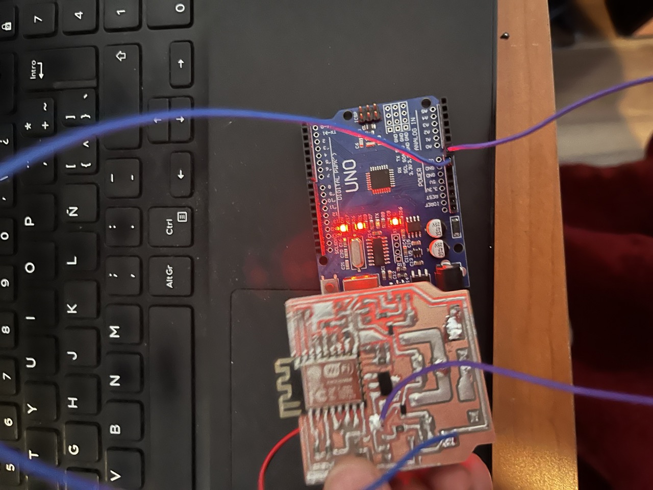
HOW IS IT ALL CONECTED HONEY?
ALL ABOUT THE FUNCTION
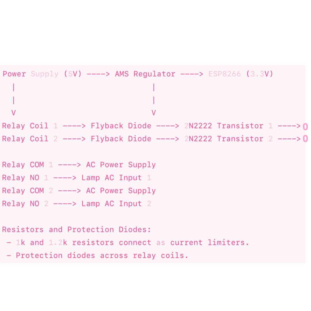
To understand how this board works, imagine 5 volts of power arriving and going to the relays. To activate them and allow current to pass through, we need the ground connection (negative). This is where the transistor comes in: it acts as a switch that controls this ground connection to turn the relays on or off. From these same 5 volts, the AMS converts part of the voltage to 3.3V, suitable for powering the ESP8266-12F. This microcontroller lights up the LEDs that power the optocouplers. These optocouplers then activate the transistors, thereby energizing the relays to turn on the lamp. This small board is perfect for switching high voltages thanks to its relays, allowing us to control 120-volt equipment with just 5 volts. The relays act as switches that control the current to turn the lamp on and off. To verify their operation, run a blink code on Arduino. The components include 1.2kΩ and 1kΩ resistors, 10kΩ resistors, diodes, a flyback diode, an AMS, 4N25 optocouplers for power and control separation, 2N2222 transistors, and extra pins for programming. Use a programmer board with the CH340 chip to power the relay board and control the lamp with a blink code. Additionally, use the CH340 TTL for programming the board and detecting humidity and temperature in the environment with a dedicated sensor.
NOW LET´S SEE HOW EVERYTHING WORKS IN THIS SCHEMATIC
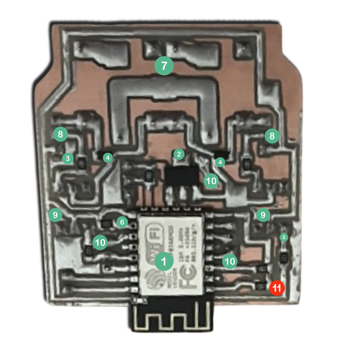
P O W E R - S U P P LY (5V) Provides the main voltage source for the entire circuit.
R E L A Y S Act as switches to control high-voltage devices (up to 120V AC) using low-voltage signals (5V DC). They toggle the lamp on and off based on the signals received from the ESP8266.
T R A N S I S T O R S 2N2222 These transistors are used as switches to control the relays. When the ESP8266 sends a signal (through optocouplers), it activates the transistors which, in turn, energize the relay coils, allowing current to flow through to the lamp.
O P T O C O U P L E R S 4N25 Optocouplers are used to electrically isolate the high-voltage side (relays and lamp) from the low-voltage side (ESP8266). They ensure that there is no direct electrical connection between the two sides, providing safety and preventing interference.
A M S Assuming AMS1117 Voltage Regulator Converts the 5V input to a stable 3.3V output suitable for powering the ESP8266 microcontroller. This ensures the ESP8266 operates reliably within its voltage range.
D I O D E S (Relay Flyback) Diodes are used for various purposes in the circuit. The flyback diode (or back EMF diode) is connected across the relay coils to suppress voltage spikes that occur when the relay switches off, protecting the transistors and other components from damage.
1.2kΩ and 1kΩ R E S I S T O R S These are used to limit current or set voltage levels in various parts of the circuit.
10kΩ R E S I S T O R S Typically used as pull-up or pull-down resistors to ensure stable logic levels in digital circuits.
C H 3 4 0 This USB to serial chip facilitates communication between your computer (or programming device) and the ESP8266 for programming purposes.
A D D I T I O N A L- P R O G R A M M I N G -P I N S These extra pins provide access for programming the ESP8266 and potentially for debugging or additional functionality.
Each component plays a crucial role in ensuring the circuit operates correctly and safely, allowing you to control the lamp through the ESP8266 microcontroller using relay switching. The optocouplers and transistors enable safe isolation and switching of high voltages with low-voltage control signals, while the voltage regulator ensures stable operation of the ESP8266. Together, they form a reliable and efficient system for your project.
SO.... maybe you can be a little bit confused with the pull_up situation here, Imma explain it 4 u girl.
In electronics, a pull_up resistor is a resistor used to ensure that a wire is pulled to a high logical level (voltage) in the absence of an input signal. It's commonly used in digital circuits to keep input pins at a defined logic level when no active driver is present.
So one end of the pull_up resistor is connected to a positive voltage supply (Vcc), and the other end is connected to the input pin of a digital logic device, such as a microcontroller or an integrated circuit (IC).
When no other active signal is driving the input pin (e.g., an open switch or disconnected input), the resistor pulls the input up to the supply voltage level, which is interpreted as a logical "high" (1).
When an external device or signal pulls the input to ground (logical "low" or 0), the pull-up resistor limits the current flowing to ground, preventing a short circuit.
Why do we use Pull_Up resistors? Well... we can prevent floating Inputs; Without a pull_up resistor, the input pin could float, resulting in unpredictable behavior because the input voltage might randomly fluctuate between high and low. →Also it ensures a stable and defined logical state (high) when no active device drives the pin. → Finally it helps define a default state for input pins in microcontrollers and other digital logic circuits.
Example in a Microcontroller.... Imagine you have a button connected to a microcontroller input pin❊→ One end of the button is connected to ground.❊→ The other end is connected to the input pin.❊→ A pull-up resistor connects the input pin to Vcc.❊→ When the button is not pressed, the pull-up resistor pulls the input pin to Vcc (logical high). When the button is pressed, it creates a path to ground, pulling the input pin to logical low.
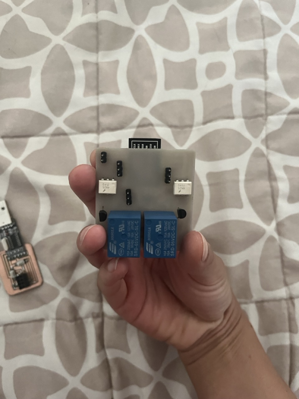
ESP8266 Microcontroller👉🏼 Our little genius that connects to Wi-Fi and makes all the magic happen. (Model: ESP8266 NodeMCU (ESP-12-F) This smart chip is like the brain of our project, with built-in Wi-Fi and lots of pins to connect everything).
Relay Module👉🏼 Think of it as the on/off switch for our lamp, controlled by our ESP8266 (Model: 2-Channel 5V Relay Module, It lets us control two devices (like the lamp situation over week 6) from our cute web page.)
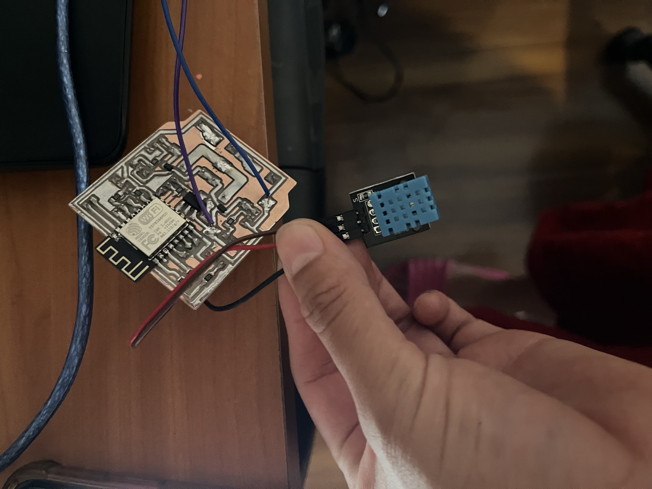
Humidity and Temperature Sensor👉🏼 To keep track of how cozy our room is. (Model: DHT22 (AM2302) It senses the temperature and humidity so we know if we need to cool down or humidify the room.)
Power Supply👉🏼 To keep our ESP8266 and relay module powered up.(Model: AMS1117 3.3V Voltage regulator module, It provides the right voltage for our ESP8266.)
Breadboard and Jumper Wires👉🏼 To connect everything neatly.(Elegoo Jumper Wire Kit and SYB-120 Breadboard, Think of it as our project’s runway, where all components are beautifully laid out and connected.)
Power Adapter👉🏼 To give life to our setup. (Model: 5V 2A Power Adapter with Micro USB Cable, This adapter powers our ESP8266)
10k Ohm Resistor👉🏼 A tiny helper to make sure our sensor works perfectly. It helps the DHT22 sensor send accurate data.
🎀VCC:Connect to 3.3V or 5V power supply.
🎀GND:Connect to ground.
🎀D1 (GPIO 5):Connect to the control pin of Relay 1.
🎀D2 (GPIO 4): Connect to the control pin of Relay 2.
🎀D4 (GPIO 2): Connect to the data pin of the DHT22 sensor.
🎀VCC: Connect to 5V power supply.
🎀GND: Connect to ground.
🎀Control pins: Connect to D1 and D2 on the ESP8266.
🎀COM, NO, and NC: Connect to the lamp or other high-power devices.
🎀VCC: Connect to 3.3V or 5V (depending on the sensor).
🎀GND: Connect to ground.
🎀DATA: Connect to D4 on the ESP8266 with a 10k ohm resistor between DATA and VCC.
SETUP The ESP8266 cute microcontroller connects to your Wi-Fi and starts a cute little web server. It also initializes the relays and the DHT sensor so they're ready to go.
WEB CONTROL You can control your relays (and therefore your lamp) from any web browser by visiting: http://192.168.1.1/relay1/on to turn on Relay 1 (and the lamp). http://192.168.1.1/relay1/off to turn off Relay 1. Similarly, use /relay2/on and /relay2/off for Relay 2. In this particular case I just used it as an access point cuz I didn´t needed to control the lamp here (check that out at output device week) I just needed it to print the resultas.
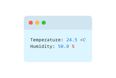
READING SENSOR DATA
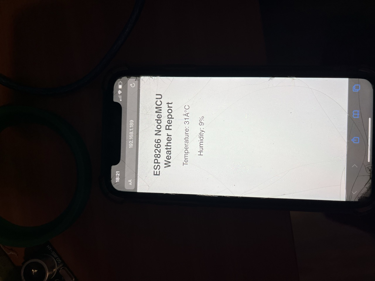
Visit http://192.168.1.189/dht to see the current temperature and humidity in your room.
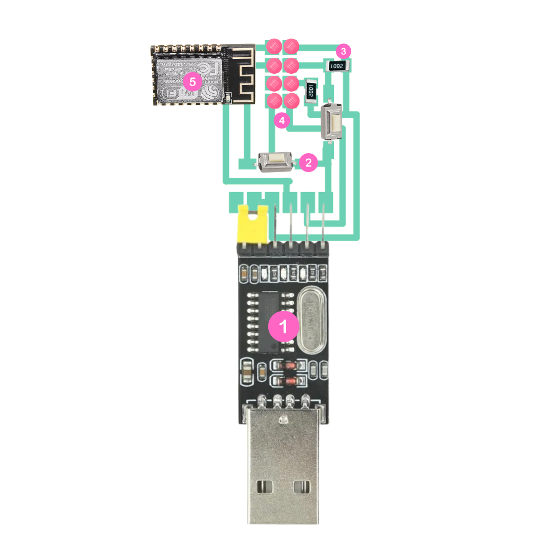
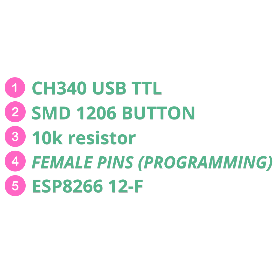
🌸CH340 USB to TTL The heart of the programmer board, this chip converts the USB signal from your computer into TTL (Transistor-Transistor Logic) signals that the ESP8266 understands.
🌸2 SMD Buttons One button is used to put the ESP8266 into programming (flash) mode, and the other is for resetting the ESP8266.
🌸2 10k Resistors These resistors act as pull-up resistors to ensure that the GPIO pins of the ESP8266 have a high logic level when the buttons are not pressed.
🌸6 Female Pins These allow you to securely connect the ESP8266 12-F to the programmer board.
- NETWORKING AND COMS WEEK
ALL ABOUT THE CONNECTIONS..
CH340 → USB Connect the USB port of your computer to the input of the CH340. This chip will convert the USB signals into TTL signals for the ESP8266.
SMD BUTTONS Connect one button between GPIO0 and ground (GND) for programming mode, and the other button between RST and ground for resetting.
10k RESISTORS Connect the resistors between Vcc (3.3V) and the GPIO0 and RST pins to act as pull-up resistors.
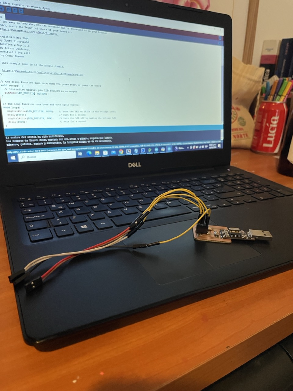
FEMALE PINS These allow you to insert the ESP8266 12-F into the programmer board.AND THE PROGRAMMING?
Okay so first you´ll need to insert the ESP8266 12-F into the female pins on the programmer board.
Then hold down the programming button (connected to GPIO0) while connecting the programmer board to your computer. This puts the ESP8266 into programming mode.
After that, use the Arduino IDE to write and upload the code to the ESP8266. The CH340 handles communication between your computer and the ESP8266.
Once the code is loaded, press the reset button (connected to RST) to restart the ESP8266 and run the new code.
SO IN A NUTSHELL... Imagine your ESP8266 12-F getting ready for a glamorous makeover! The CH340 USB to TTL chip is like the ultimate stylist, transforming signals from your computer into something your ESP8266 can understand. With two chic SMD buttons, you can elegantly put your ESP8266 into programming mode or give it a quick reset. The 10k resistors are like those perfect accessories that ensure everything stays in place, making sure the signals are just right. And those 6 female pins? They're the runway where your ESP8266 struts in to get programmed. With the help of the Arduino IDE, you can send your code, and voilà! Your ESP8266 is ready to shine with new instructions. Simply fabulous, darling! 💖✨
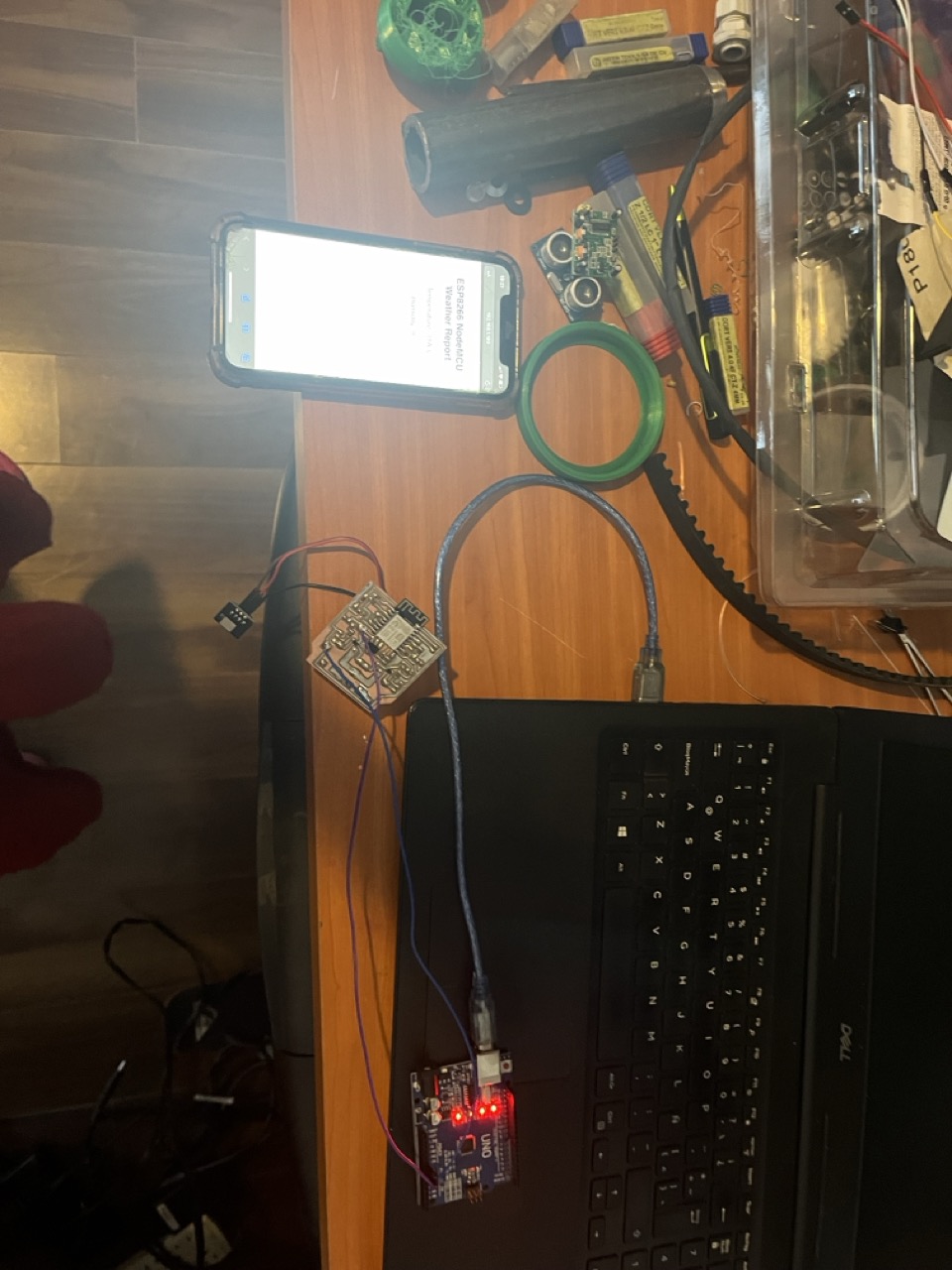
👆🏽THE PLUG + FINAL PROJECT 🎀BOARD🎀👆🏽
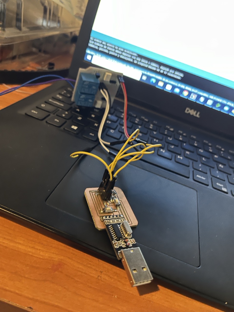
👇🏽THE PLUG + MY OUTPUT DEVICE🧸✨👇🏽
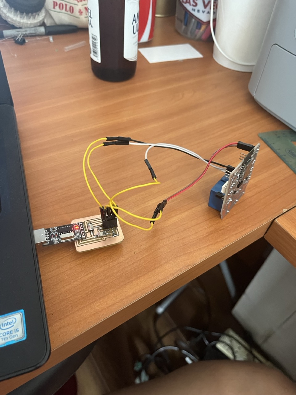
NOW HOW I CONNECTED THE CH340 TTL PROGRAMMING BOARD🎀 TO MY FINAL PROJECT BOARD🎀
So rember honey, if you wanna see the results and everything about the design of my final project´s board always go to THIS LINK
- SHOWSACK
Soooo gurl I made a super chic setup where the ESP8266 12-F, acting as an access point, lets users connect their cellphones to interact with it through an HTML page. This fabulous device allows you to manage and switch between different modes with ease. Here's a detailed yet fabulous explanation of how the CH340 plug plays a role in programming and managing this setup.
HOW?
1️⃣ESP8266 12-F as Access Point:
2️⃣The ESP8266 12-F creates its own Wi-Fi network, allowing devices like cellphones to connect to it directly.
3️⃣Users connect to the ESP8266's Wi-Fi network and access a web page hosted by the ESP8266. This HTML page contains buttons and controls for interacting with the ESP8266.
️4️⃣The ESP8266 code includes variables and modes that can be changed through interactions on the HTML page. Clicking buttons on the HTML page triggers functions in the ESP8266 code, changing these variables and modes.
5️⃣ A physical button connected to the ESP8266 can also change the variables and switch between modes, providing an alternative method of control.
How does this gets programmed?
Programming the ESP8266 12-F + CH340 The CH340 USB to TTL converter connects your computer to the ESP8266, enabling you to upload code to the ESP8266 ▶️ The CH340 handles the communication between your computer's USB port and the ESP8266's TTL (Transistor-Transistor Logic) serial interface.
Upploading code Using the Arduino IDE, you write and upload code to the ESP8266 via the CH340 plug ▶️ The code includes setting up the ESP8266 as an access point, hosting the HTML page, and defining the functions that change variables and modes.
Connecting via ACCESS POINT Turn on the ESP8266. It broadcasts its Wi-Fi network ▶️ Connect your cellphone to this network.
Interacting via HTML page Open a browser on your cellphone and navigate to the IP address of the ESP8266 ▶️ Interact with the HTML page, clicking buttons to send commands to the ESP8266 ▶️ When you click a button on the HTML page, a function in the ESP8266 code is called ▶️ This function changes specific variables, which in turn control the switch functions and modes ▶️ You can also use a physical button connected to the ESP8266 to change these variables and modes.
3 basic modes The device operates in three basic modes, managed by the switch functions in the code ▶️ These modes determine the behavior of the ESP8266 and can be changed either through the HTML page or the physical button.
HOW CAN I CONTROL IT VIA WEB CONTROL? WELL ▶️ You can control your relays (and therefore your lamp) from any web browser by visiting: http://192.168.1.1/relay1/on to turn on Relay 1 (and the lamp). http://192.168.1.1/relay1/off to turn off Relay 1. Similarly, use /relay2/on and /relay2/off for Relay 2. READING SENSOR DATA Visit http://192.168.1.189/dht to see the current temperature and humidity in your room.


1️⃣Serial Communication Data → is transmitted one bit at a time over a single wire, allowing two devices to communicate. 2️⃣Asynchronous → No clock signal is required → devices must agree on the baud rate (speed of data transmission).
🌸Components Involved🌸
TX (Transmit) → Sends data from the sender.
RX (Receive) → Receives data from the receiver.
GND (Ground) → Common ground connection.
What about the data format? 1️⃣Start Bit → Indicates the beginning of data transmission. 2️⃣Data Bits → The actual data being transmitted (usually 8 bits). 3️⃣Parity Bit → Optional error-checking bit. 4️⃣Stop Bit → Indicates the end of data transmission.
-
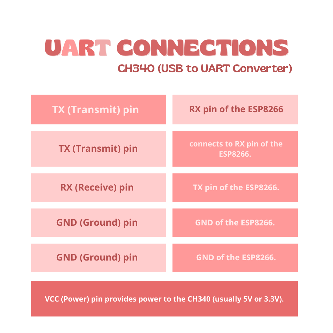
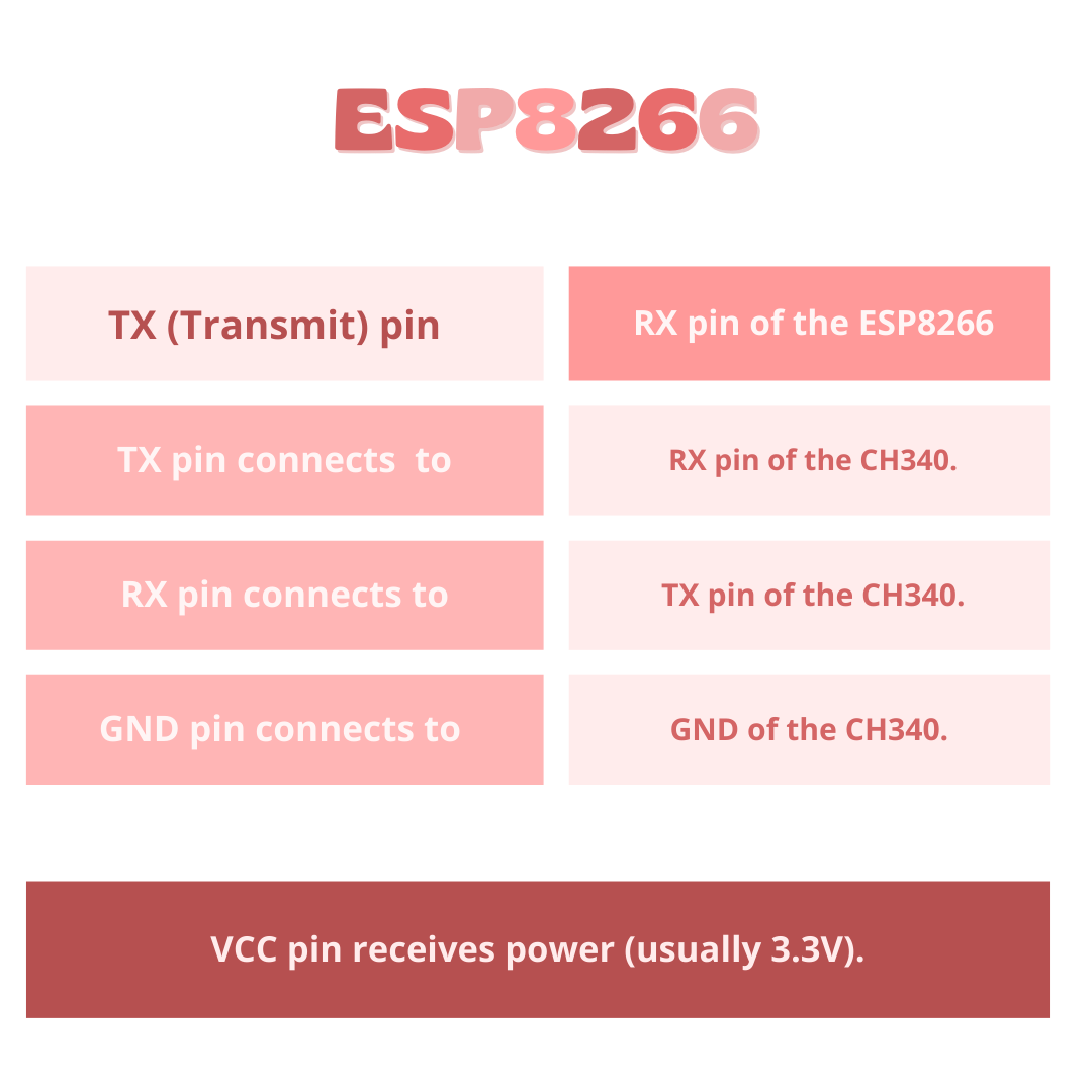
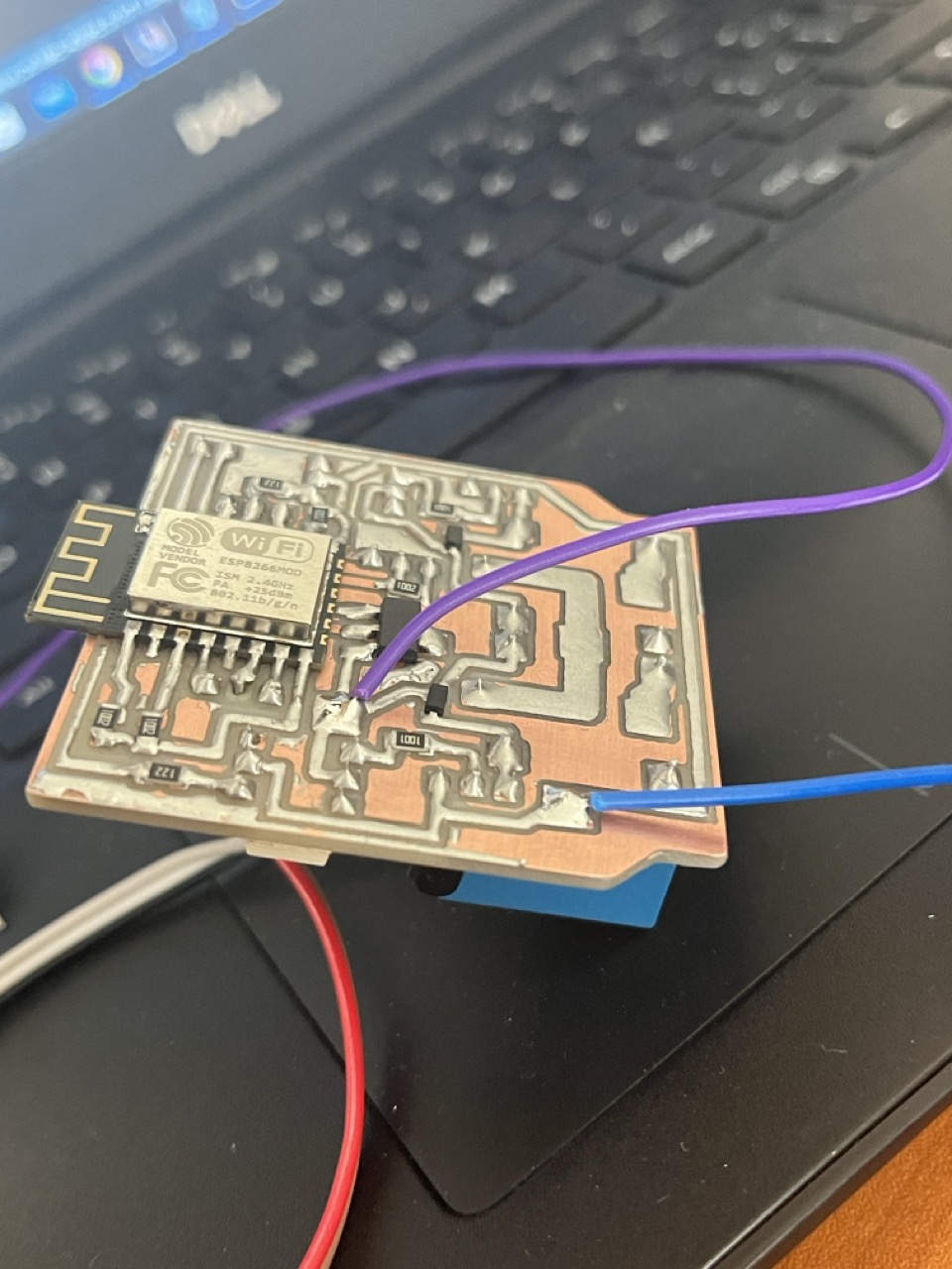
1CH340 USB → TTL Connections
TX (CH340) to RX (ESP8266)➡️ Connect the transmit pin of the CH340 to the receive pin of the ESP8266.
RX (CH340) to TX (ESP8266)➡️ Connect the receive pin of the CH340 to the transmit pin of the ESP8266.
GND (CH340) to GND (ESP8266)➡️ Connect the ground pin of the CH340 to the ground pin of the ESP8266.
3.3V (Power)➡️ Ensure that the ESP8266 is powered correctly, typically with 3.3V.
-
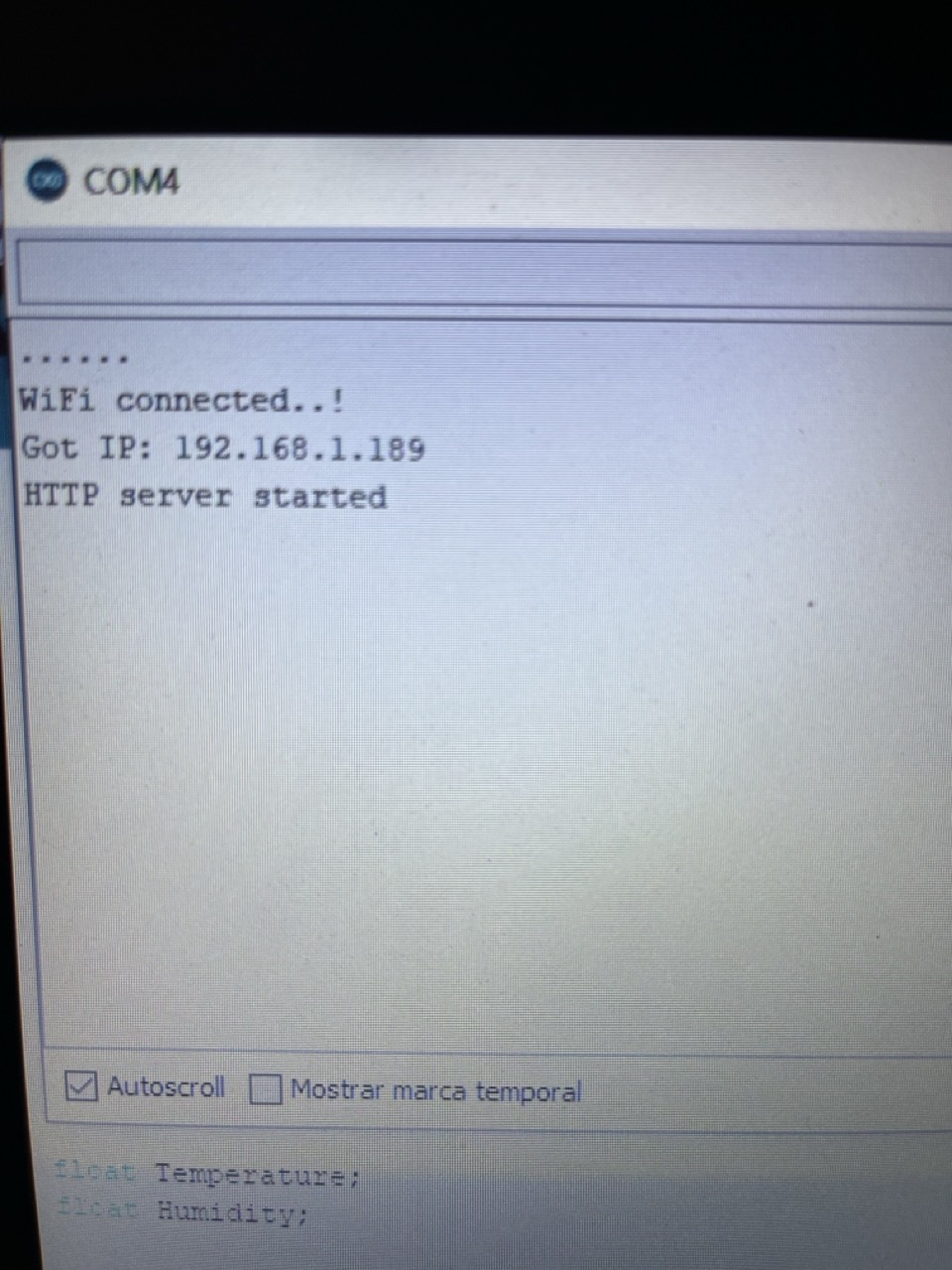
2Programming the ESP8266Install Drivers Ensure CH340 drivers are installed on your computer. ➡️ Connect via USB Plug the CH340 into your computer’s USB port. ➡️ Upload Code Use the Arduino IDE or other compatible software to upload code to the ESP8266.
-
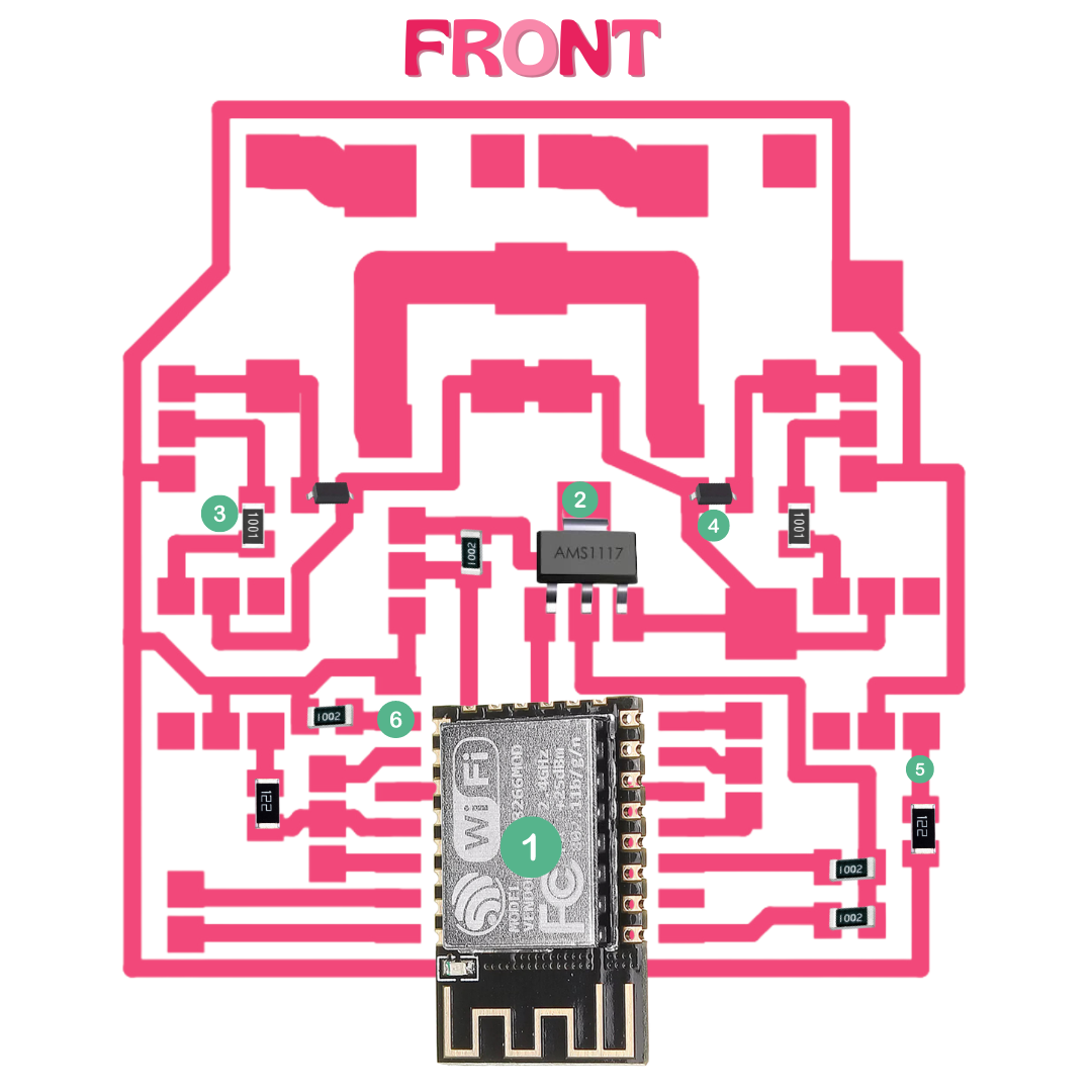
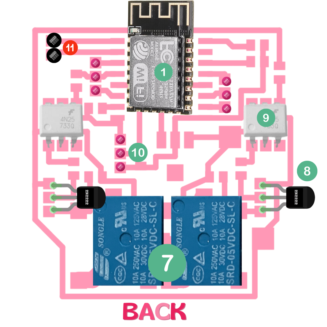
3Board Components
1️⃣AMS1117 3.3V Regulator▶️ Converts higher voltage to 3.3V for the ESP8266.
2️⃣Resistors and Capacitors▶️ Ensure stable operation of the ESP8266 and peripheral components.
3️⃣Optocouplers (4N25)▶️ Isolate the control signals from the high-power circuits.
4️⃣Transistors (2N2222)▶️ Switch high-current loads like relays.
5️⃣Relays and Flyback Diodes▶️ Control high-voltage devices and protect circuits from voltage spikes.
- The ultrasonic sensor code
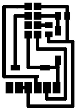
- png file plug
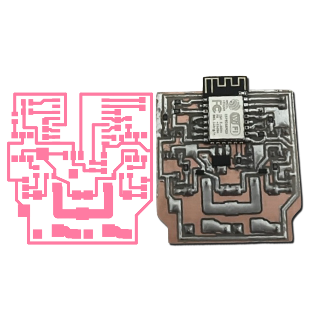
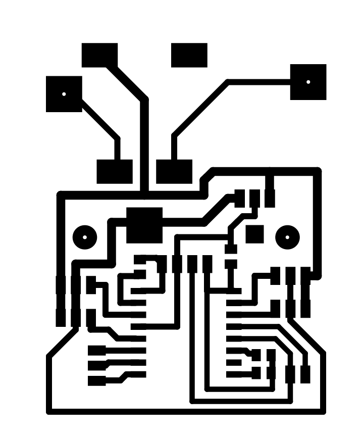
- png file relays board
- png file showsack board
- Temperature sensor code
- Relays code
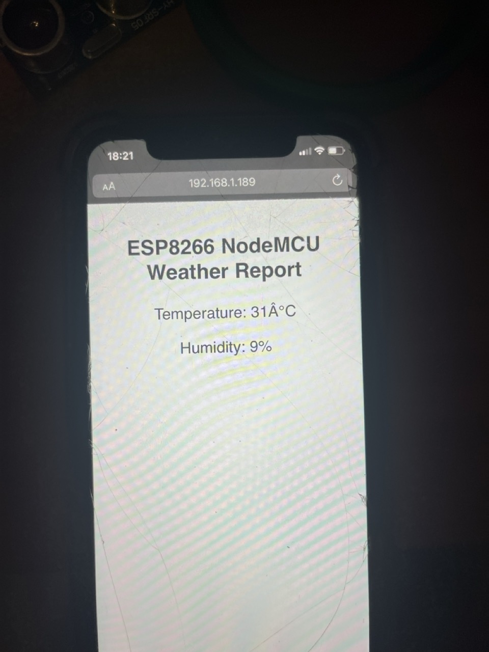
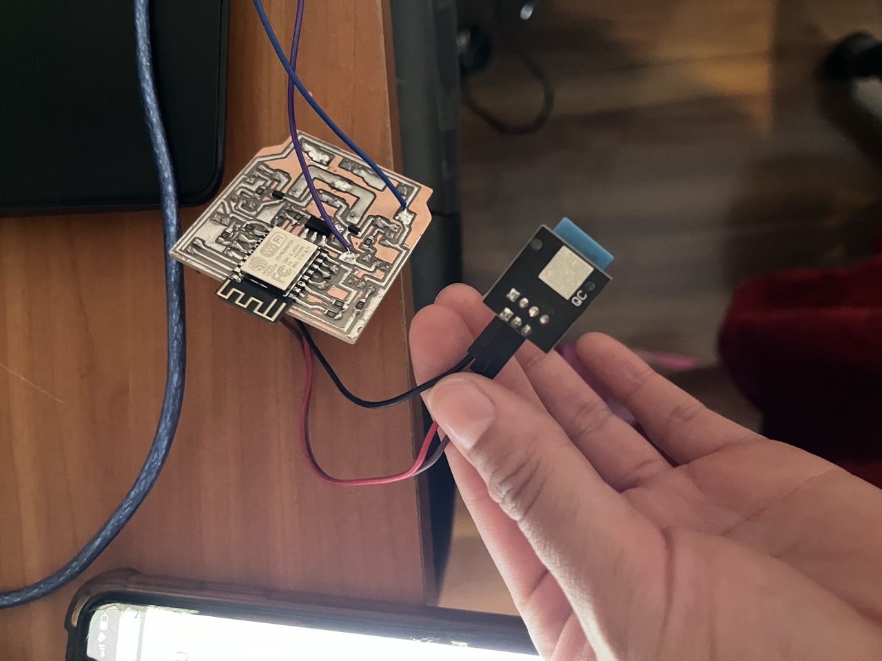
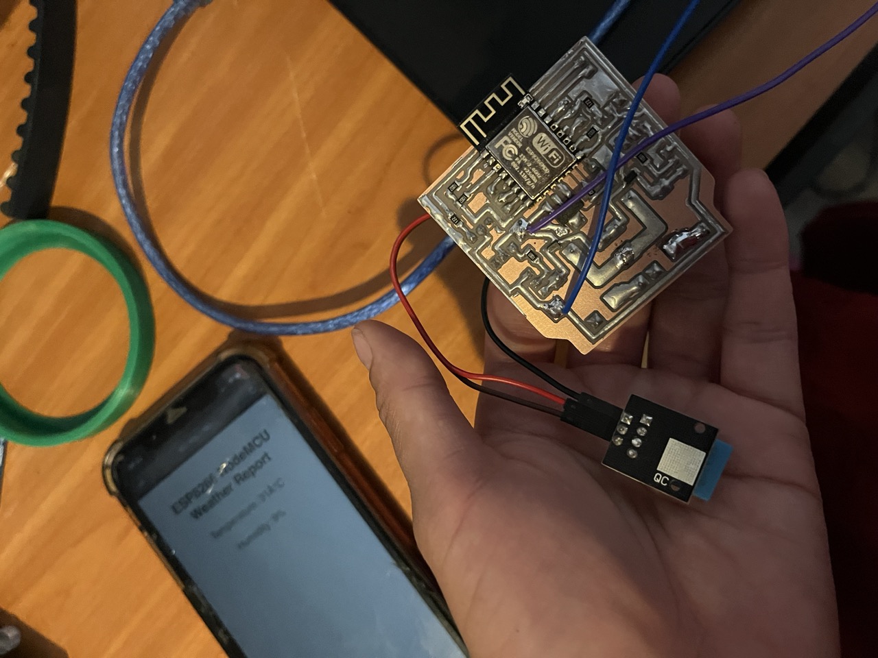
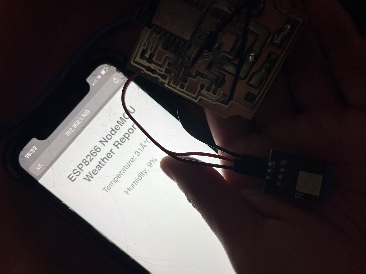
SO TO TRY IT ON I DECIDED TO USE A TEMPERATURE/HUMIDITY SENSOR IN THE BOARD PROGRAMMING IT WITH THE PLUG
AND IT WENT LIKE THIS...
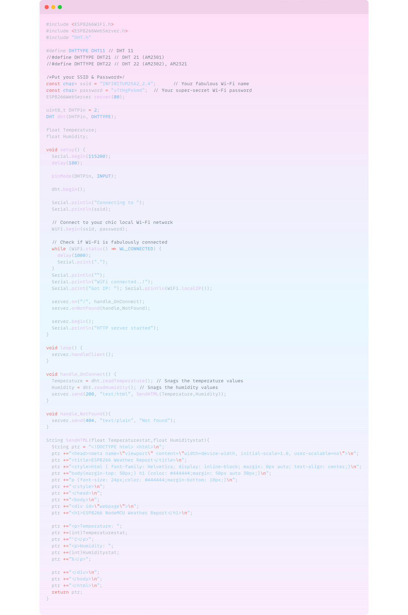
Now, let's add some magic to our home by using the ESP8266 and a DHT22 sensor to monitor temperature and humidity. With a cute web page, you'll know how cozy your room is at any moment. ✨
IN A NUTSHELL IT WORKS SUM LIKE THIS -----> Your ESP8266 connects to your Wi-Fi network and sets up a web server. The DHT22 sensor, connected to the ESP8266, constantly measures the room's temperature and humidity. When you navigate to the specified IP address (e.g., http://192.168.1.189/dht) from any web browser, the ESP8266 processes your request. It reads the data from the DHT22 sensor and then displays the current temperature and humidity on the web page. In the code, we define routes for the web server to handle different requests. The handleDHTRead() function reads the sensor data and formats it into a user friendly message. The ESP8266 then sends this message back to your browser. This setup lets you monitor your room's environment in real time, ensuring it's always cozy and comfortable. With just a few components and some code, you create a magical, smart home feature that's both practical and fabulous! 💖
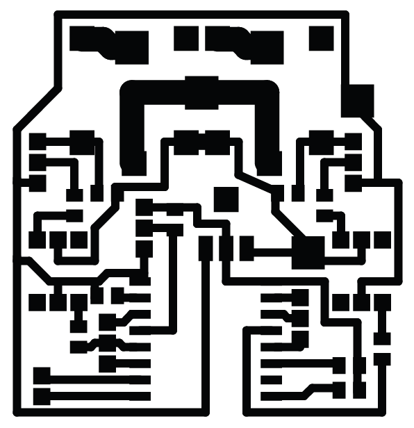
So for the electronic design software I used PCB wizard cuz honestly I don´t like at all KiCad, for me it was so much easier to draw what I wanted for the components disposure and to draw lines between them so I understood it better. I used the Roland SRM for the milling process and used obviously MODS for the programming, Vcarve for the cutting process software, but you can see the pics and parameters on the electronic design week, I really prefer that you´ll totally embed your attention in the programming and all this Data for this week hun. I´ll give you a little sneak peek here:
Components You’ll Need
HOW TO CONNECT EVERYTHING circuit design
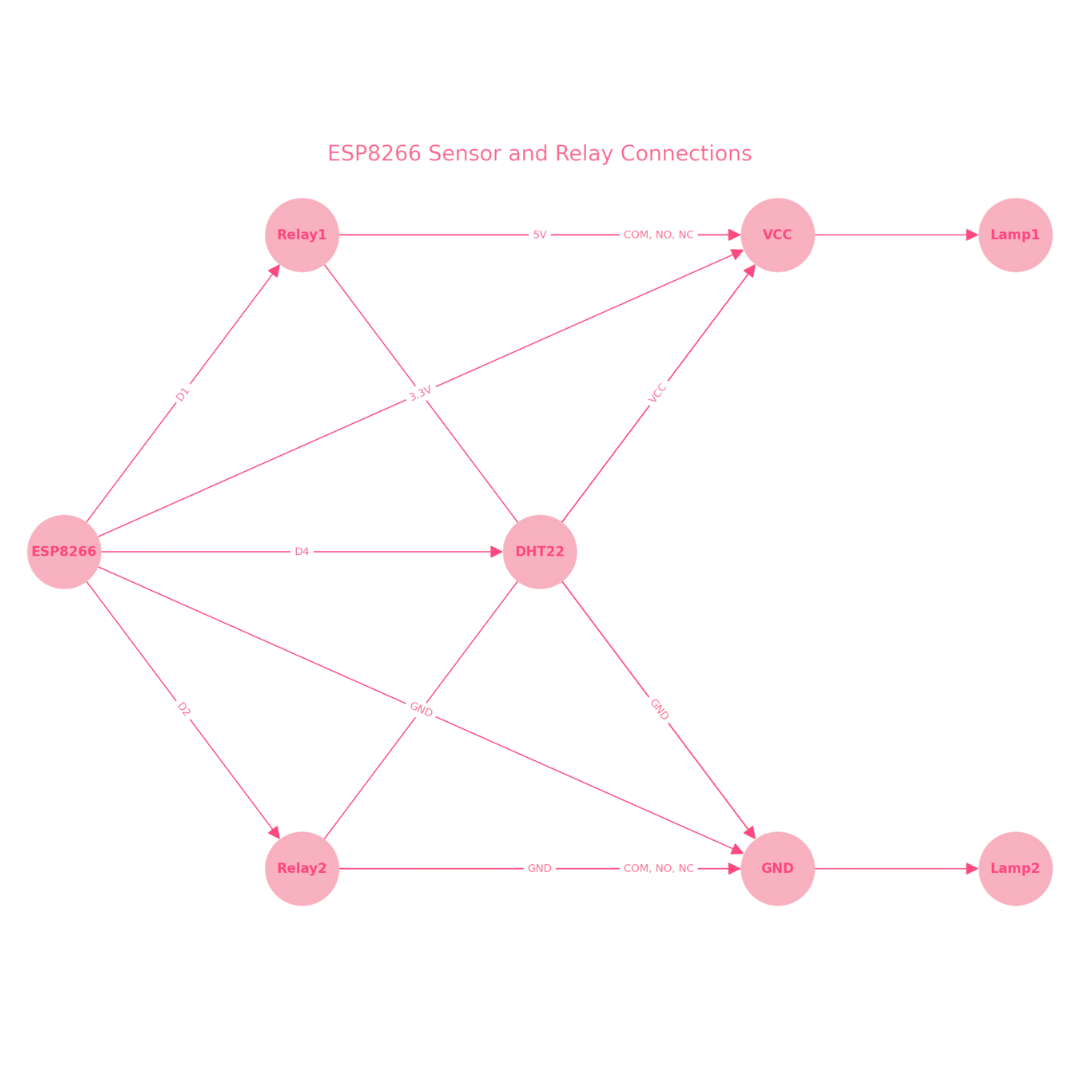
ESP8266 Connections
AND THE RELAY CONNECTIONS?
DHT22 SENSOR CONNECTIONS...
How it all works together like a perfect family
Look at the gorgeous final pictures carousel
❀✿REMEMBER THAT THIS IS A CAROUSEL CLICK THE ➤ TO SEE ALL THE PICS!!❀✿


Okay now eveything about the programming CH340 PLUG YAAAS
Okay so this BOARD🎀 will be featured in the final project and used for another projects purpose here at Fab Academy so I´mma explain it super detailed sweetie... First this board features two SMD buttons, a CH340 USB to TTL chip, two 10k resistors, and six female pins for connecting the boards to program. Everything was programmed using Arduino, and you managed to program all your fabulous projects with this board.
HOW THE PROGRAMMER BOARD WORKS GURL?
Okay so its main components are:
IF YOU TOTALLY WANT TO KNOW EVERYTHING ABOUT HOW IT IS ALL CONNECTED AND WORKING CLICK HERE👇🏽
SO IN A NUTSHELL...The ESP8266 12-F is creating its own Wi-Fi hotspot, like a fabulous party! Guests (a.k.a. your cellphone) connect to this hotspot, where they find a glamorous HTML page with buttons to interact with. These interactions send signals to the ESP8266, changing its variables and switching modes with elegance and ease. The CH340 plug is your stylish programmer, connecting your computer to the ESP8266 so you can upload dazzling new code. Whether through the HTML page or a physical button, you effortlessly switch between three fabulous modes, making your project the life of the party! 💖
HOW IS THIS AN UART PROTOCOL TOO HUN?
So as y´all know sweetie, UART (Universal Asynchronous Receiver/Transmitter) protocol is a communication method used for serial communication between devices. It allows the ESP8266 12-F and the CH340 plug to exchange data efficiently. Here’s a super chic breakdown of how it works:
HOW DO I CONNECT THE PLUG WITH THE ESP?
To program and communicate with the ESP8266 12-F, the CH340 plug acts as a bridge between your computer and the ESP8266. Here’s a chic guide to making these connections and understanding how it all works with your board components...
SO FOR BETTER UNDERSTANDING...In this fabulous setup, the CH340 plug acts as a stylish programmer and communicator for the ESP8266 12-F. The UART protocol ensures seamless data transmission, allowing you to program and interact with the ESP8266 effortlessly. Your board’s components, including voltage regulators, resistors, capacitors, optocouplers, transistors, and relays, work harmoniously to switch high-voltage devices like a chic lamp on and off, making your project both functional and fabulously chic. 🌟✨
🎀And now... my pretty table of the final project 🎀BOARD🎀 components
SOPHIE´S FABULOUS SHOWSACK COMPONENTS |
Where to buy? | Amount | Price | Total price |
| AMS1117 3.3V | Digikey | 1 | $12.80 MXN/unit | $12.80 MXN |
| ESP-12-F | Mercado Libre | 1 | $90.00 MXN/unit | $90 MXN |
| Microswitch 1 pole 2 throws 2 positions | Steren | 1 | $5.00 MXN/unit | $5.00 MXN |
| SMD capacitor 1206 10kΩ | Yageo | 4 | $37.00 MXN/unit | $24.66 MXN |
| Servomotor with 10 kgf/cm torquer | Steren | 4 | $174.00 MXN/unit | $696.00 MXN |
| 3.7V 1600mAh LiPo battery | Amazon | 1 | $183.86 MXN/unit | $183.86 MXN |
| TP4056 board with step-up | Mercado Libre | 1 | $69.00 MXN/unit | $69.00 MXN |
| Copper plate | Mercado Libre | 1 | $90.00 MXN/unit | $12.85 MXN |
| Button | Unit electronics | 1 | $4.00 MXN/unit | $4.00 MXN |
| Total cost | $1098.17MXN |
Take a look of my pretty construction 🪸carousel🪸
❀✿REMEMBER THAT THIS IS A CAROUSEL CLICK THE ➤ TO SEE ALL THE PICS!!❀✿


Soooo why using this gurl?
All about the ☀️C️O️D️E️️S
The ESP8266 12-F and the CH340 USB-to-TTL module communicate using the UART protocol, which is like a chic chat over a fabulous data connection. The UART protocol sends data between the ESP8266 and the CH340 plug in a super sleek and orderly way, with each bit of data dressed to perfection. When you upload the code to the ESP8266, the CH340 acts like a glamorous bridge, converting USB signals from your computer into TTL signals the ESP8266 understands. This ensures your fabulous ESP8266 can be programmed and communicate flawlessly, making your relay board perform perfectly chic and cute light control magic.
My fab files
So this is everything for my week of ✨NETWORKING and coms! I hope you ejoyed it as much as I enjoyed doing it ISH!