Electronic´s production 🩰
Hey there sis, welcome to this week's assignment where we're diving into the world of PCB fabrication! Get ready for some really cool pink stuff ahead.
First of all I will explain what PCB fabrication is all about. So, basically, special gorgeous machines that are programmed to do this take our digital designs and turn them into real-life circuit boards. It's just like a carving wizzard omg🌟 they use this super fast cutter to carve out pathways on copper boards, making the circuits we need. The minimum trace width on a PCB is like the narrowest path it can take, it is like a little highway for electricity. It's super important because it keeps things from overheating or breaking when carrying current.
And then there's the number of layers - I like to think of it like building a skyscraper! More layers mean more room for cool stuff without making the board bigger. But you gotta find the right balance because it affects how well everything works and how much it costs so be careful, we are not millionaire´s...YET😎💸
Unlike those big machines that the current industry uses, here at the FabLab Puebla we use Mini-Millst wich are all about detail, thanks to their fancy software. For this assignment I personally used the ROLAND SRM-20 model gurl, AND YES, I had my own personal wizzard carving my own pretty design.✨
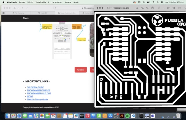
I will recomend that you read your machine´s guide so you´ll know perfectly what to do, here´s mine:
So smh important that I had forgotten to tell you is that this Mini-Millst can work with all sorts of materials, from modeling wax to acrylic and even wood, what a nice gig huh? Plus, also something VERY important I have to tell you too is that here we have some safety guidelines to follow to keep everything running smoothly and safely in the workshop, like always operate with one person at a time and wear eye protection.
Finally here at the FabLab Puebla, when it comes the time of making PCBs, we've got some really cool tools like the one I used that is a pretty 15-degree V-bit for engraving and a 0.8mm diameter two-flute end mill for cutting. Also I recommend you to use this cool software called MODS to make things easier. Trust me, it's a bit intimidating at first, but once you get the hang of it, it gets better!🌺
✨Massive shoutout to our instructors for their engaging and enlightening session, guiding us toward mastering the art of PCB fabrication here at the FabLab Puebla. With these insights, we're ready to unleash our creativity and innovation using this new tech! Thank you!!🧸
Our group weekly task
⬇️
Converting the 🎀files🎀 into Gcode (setting that toolpath)
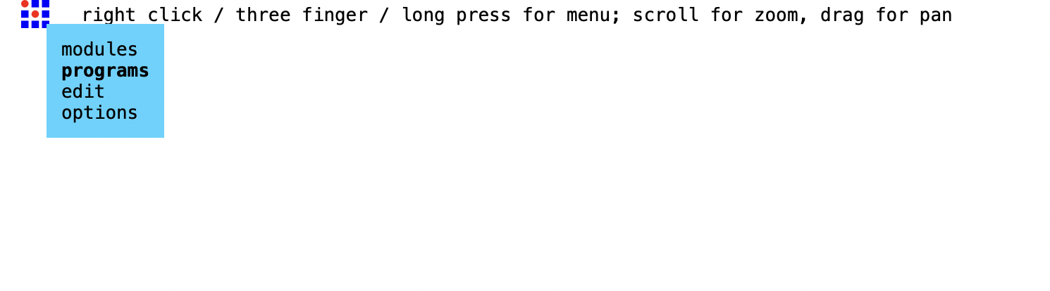
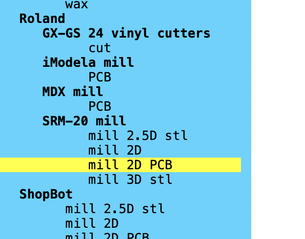
First things first, I visited the server and got ready to dive in (okay I was very nervous). Once I was in, I opened the program and selected the Roland SRM-20 PCB option.
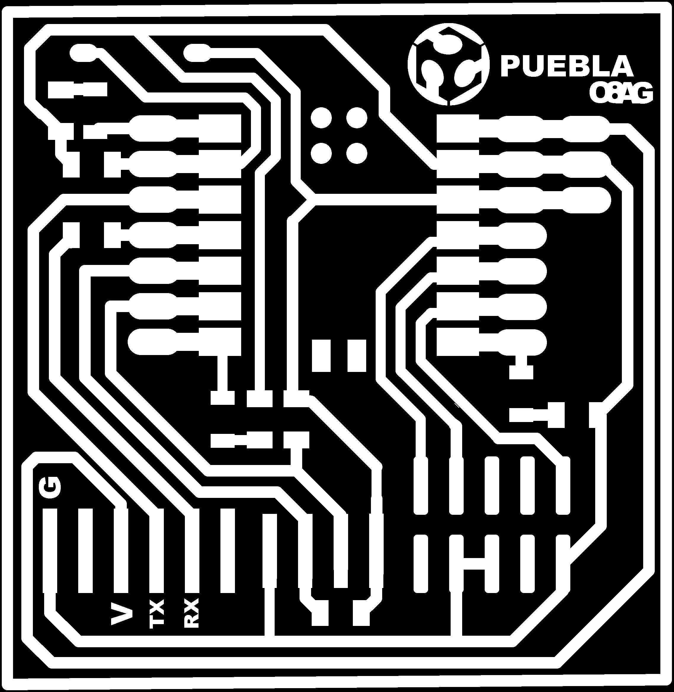
Next up, I chose the PNG file I wanted to carve. It's all about picking the right design but for this assignment our FabLab Puebla friends gave me everything I needed for an amazing carving experience. I learned that there are servers like ------- and ----- that will help you design your PCB. Then, I left the defaults as they were (because hey, if it ain't broke, why fix it?).
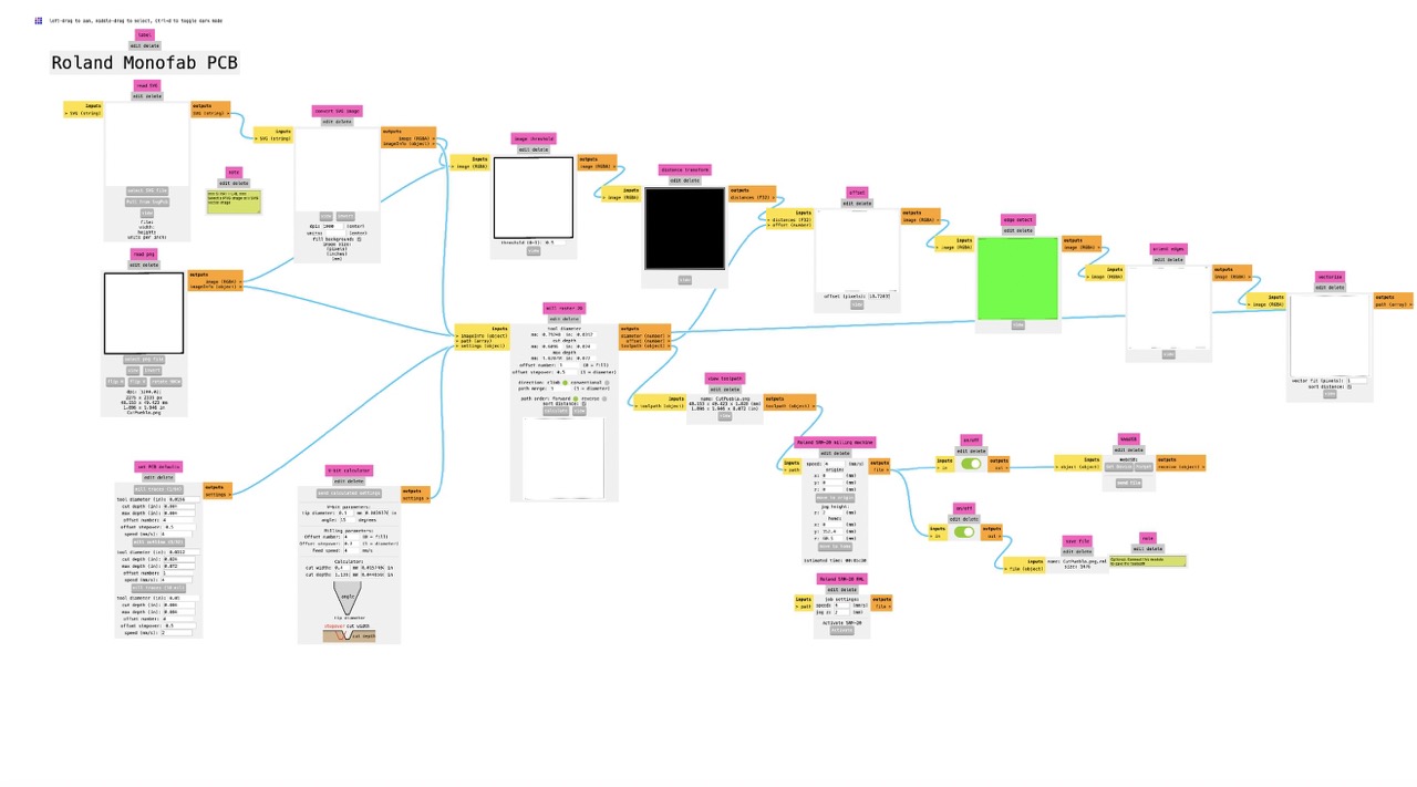
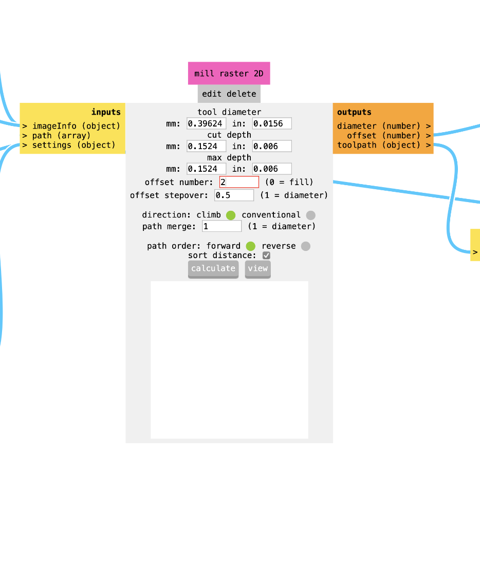
After that, I headed straight to the Mill Raster 2D option. Here's where the magic of the wizzard happens! I gave it a 2 offset number—just a little tweak to make sure everything turns out perfectly.
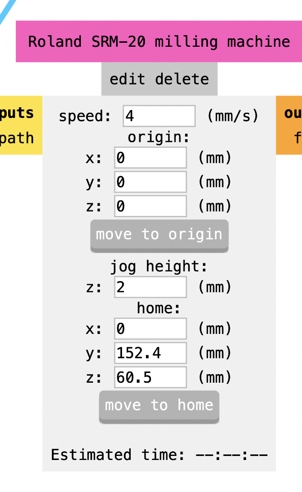
Now the next step: setting the x, y, z values to zero. It's like telling the machine, "This is your origin" Getting those coordinates right is key to getting the perfect carve (among other things of course).
And finally, the moment of truth: I hit download! The file saved with a .rml ending, like a digital signature saying, "I'm ready to carve, sooo hungry for the copper plate guuuuuurl!"
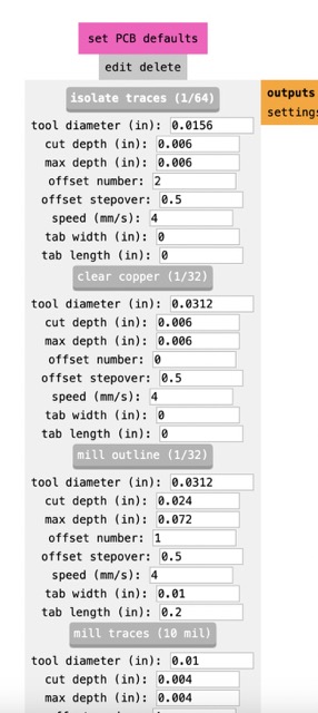
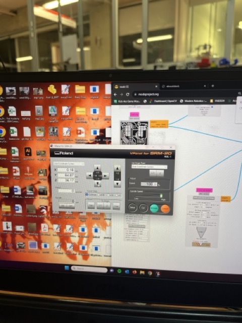
This were my beautiful parameters:
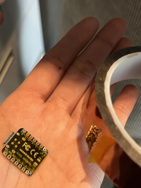
- Your cute Seeed Studio XIAO RP2040
- Your pink PC
- USB Type-C cable
- Step 1: Download and Install the latest Arduino IDE for your operating system.
- Step 2: Launch the Arduino application.
- Step 3: Add Seeed Studio XIAO RP2040 board package to your Arduino IDE:
- Go to File > Preferences, and paste this URL in Additional Boards Manager URLs: https://github.com/earlephilhower/arduino-pico/releases/download/global/package_rp2040_index.json
- Then, go to Tools > Board > Boards Manager..., type "RP2040" in the search box. Choose the latest version of "Raspberry Pi Pico/RP2040" and install it.
- Step 4: Select your board and port. Usually it starts with a “COM” in it
- Step 5: Open the example code by going to "File --> Open". (Here I opened the one our instructors gave us for this week’s assignment but you do you).
- The code PER SE 🤌🏼
- Step 6: After installing the board package, go to Tools > Board, find "Seeed Studio XIAO RP2040", and select it. Boom, we've set up our Seeed Studio XIAO RP2040 for Arduino IDE!
- Step 7: Go to Tools > Port and choose the serial port name of the connected Seeed Studio XIAO RP2040. It's usually COM3 or higher, and it often has "Seeed Studio XIAO RP2040" in parentheses.
- Step 8: Hit the Upload button to upload the example code to the board.
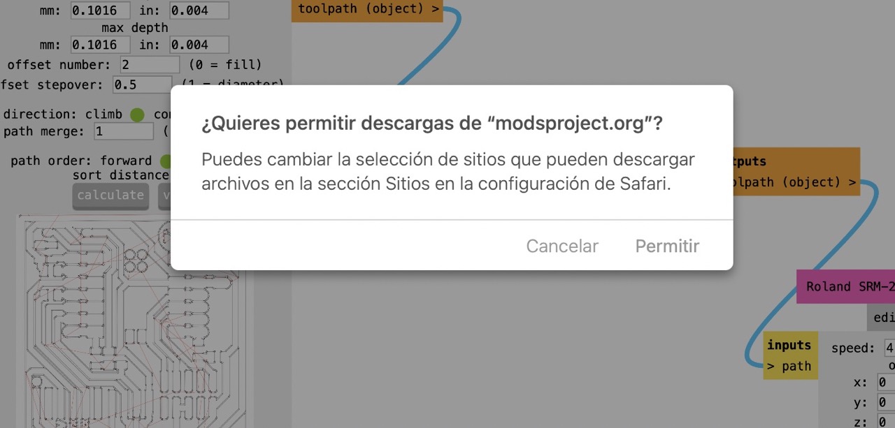
Okay so for the correct reading of my file in the gorgeous ROLAND SRM-20 machine I had to generate my GCode in the Mods CE server. Let me break down the steps for you because even tough it looks a little bit difficult, it will be easier than you think.

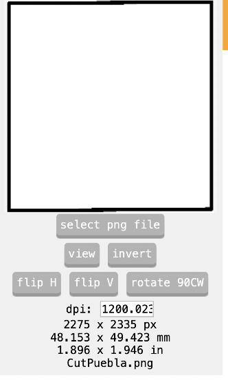
For the cut image I had to hit the invert button so the Roland could carve just where I wanted it
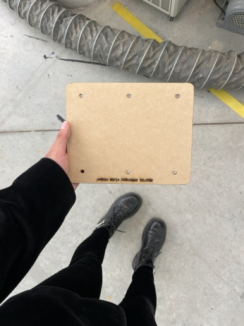
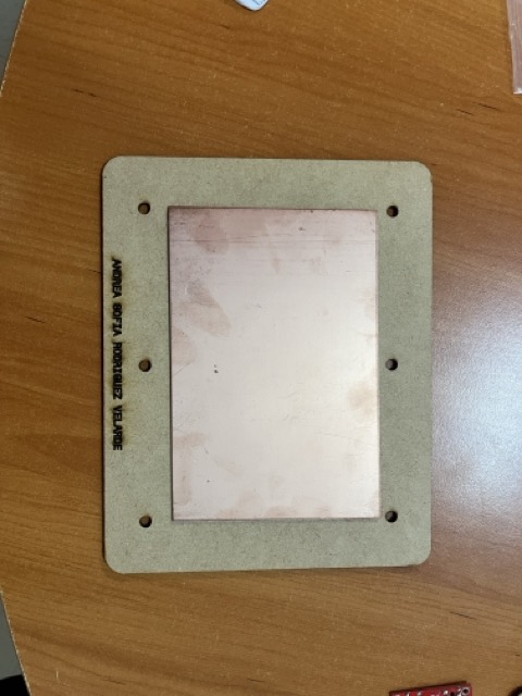
My sacrificial bedding ⚰️💀
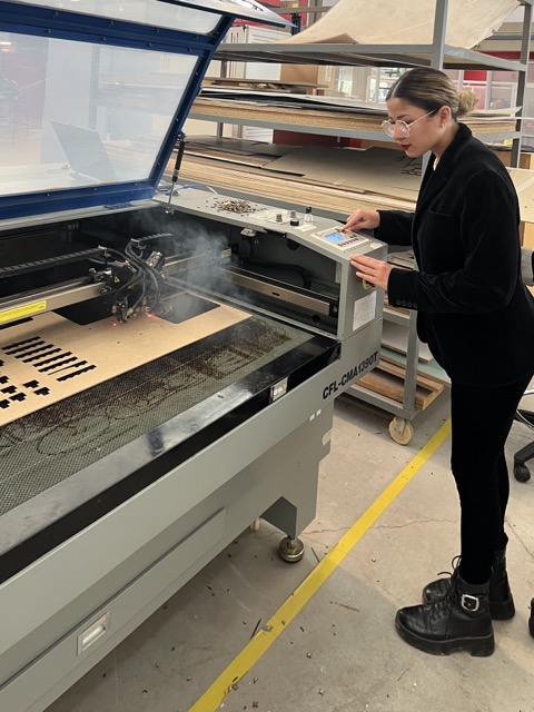
For this week's assignment, we had to cut a sacrificial bed in MDF to fit the Roland machine's measurements so we wouldn't mess up the aluminum panel underneath. Our teachers hooked us up with a DXF cutting file, so I went ahead and cut and engraved it using the laser cutter.
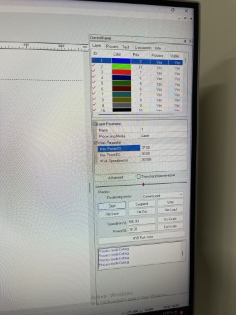
This were the parameters that worked out for me and my graving and cutting situation
Max power: 37%
Min power: 30%
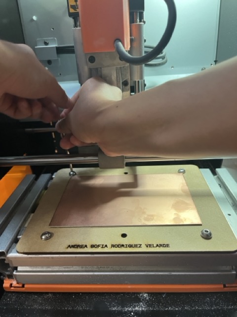
Vpanel instructions but CUTE🌷 (setting that toolpath part 2)
Okay so imma tell you what you need to know to about the Vpanel program to get the ROLAND SRM-20 machine to do its thing on your pretty copper plate, here's the deal: First, I calibrated in x, then in y, and then the z-axis is where we mark our starting point. So, I swapped out the engraving tool for this super cool V-angle one. After I finshed, I did another calibration, but this time just in z, so I could pop in my 0.8 mm diameter cutting tool. Oh, and remember, when you're putting your tools in the holder, make sure it's not too tight! Gotta leave it loose so we can do that last bit of calibration by hand and make sure it's all perfect. Don't wanna break the tool when it goes down in z, you know girl...?
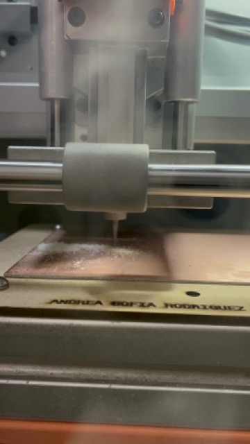
AND NOW IT IS SOOOO PRETTY AND SOOOO READY BABE✨💫✨
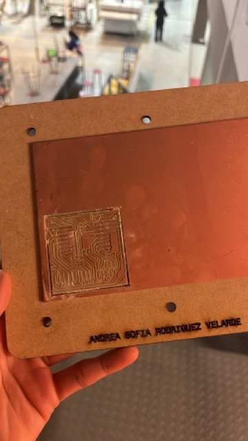
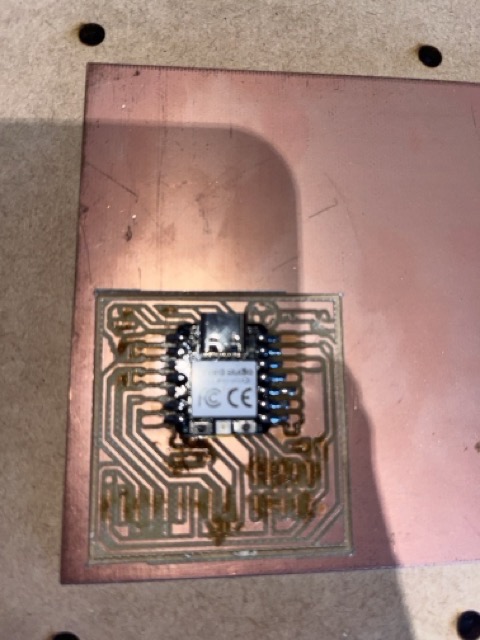
And now... all about my nice board 💕 (stuffed and soldered)
Okay so first things first... I prepared my surface first, using white vinegar and salt to clean it up. Gotta get rid of those pesky fingerprints☝🏼 and prevent any copper oxidation, RIGHT?
Next up, I dabbed some soldering paste exactly where my components needed to sit down. I had to make sure they were in the right spot before I hit them with the soldering iron. They looked just like if they were a cute little fam.
Then, I whipped out my boyfriend´s trusty and rusty😂 Kapton tape. It's like the outer space version of tape, super sleek and pro-looking (Totally what I wanted). I used it to shield the bottom part of the Xiao board, keeping things pro and techy with that aerospace-grade polyamide (AGAIN).
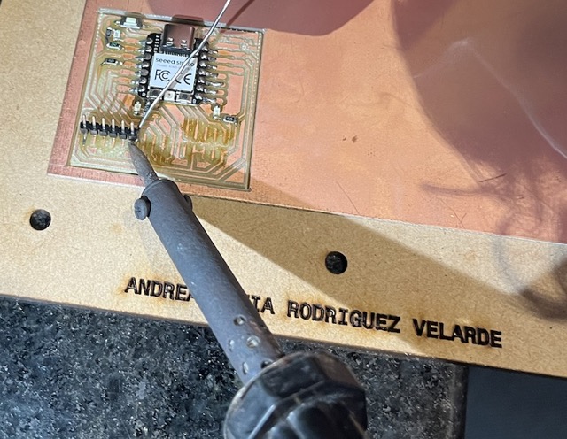
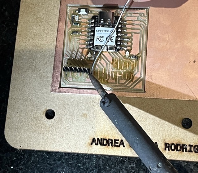
And finally the inevitable happened... I DID IT. First I had my gear ready: 3 LEDs, 5 resistors, a cute button, 20 pins, and that sweet Xiao board. Then, I tack down those Xiao corners to keep it steady. Then, it's LED time followed by resistors. Remember, quick soldering motions and keep it clean, no more than a second per spot. Finally, those pins go in vertically for easy handling, and BLOOM🌸🌺🪷🌼! Board's looking sharp with some seriously slick soldering.
Feel free to take a look at my totally cute looking pics carousel:
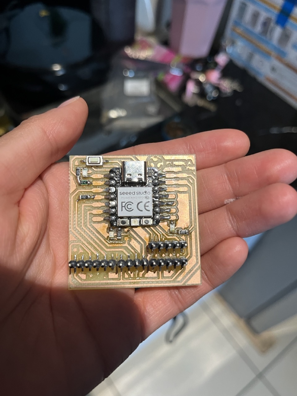
Then I pluged my baby into a Type "C" wire and turned my laptop On so it could fed my little board. This was how I knew it totally worked out!!!! Omg I swear I was so happy girl!
Very impressive young lady.. But what about the programming? 🧐
First things first, we're gonna hook up the Seeed Studio XIAO RP2040 to our computer and upload a simple code from Arduino to make sure everything's running smoothly. I recommend to use a simple blink code to see that everything is running out smoothly.
For the perfect set up you'll need:
TIP: If the Power LED on the Seeed Studio XIAO RP2040 lights up, we're good to go! If not, dissconect immediately!!!
Breakin´ it down to steps
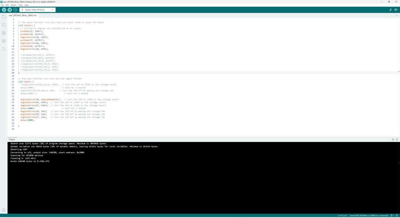
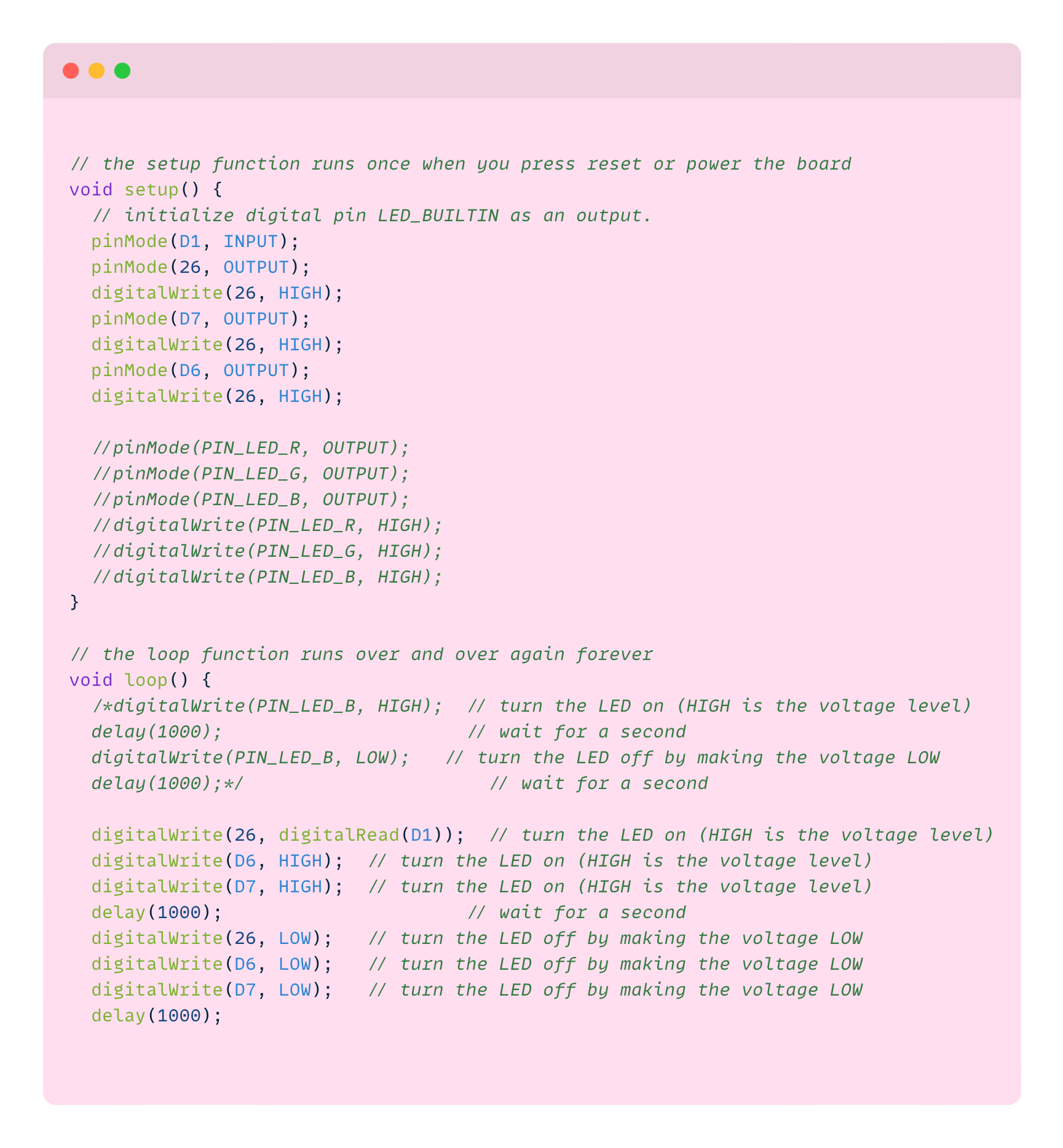
Once uploaded, watch out for the D7 and D6 LED on the board blinking once a second and D1 lighting up when you hit the button. If you see that, congratulations! You totally nailed it! LIKE ME 💅🏼🩷.
And what about the problems in this assignment?
So I know that for this week´s assignment Fab academy asked me to solve here any problems I could possibly face, in my case this was very interesting and easy to do because I have a little expience in soldering things because my boyfriend has actually taken very seriously a teacher role since a year ago that I asked him to show me how to do everything he knew. A big s/o to Javi for being so patient all this months with me and showing me how to start doing things in the electornic field💕!!!