Feeder
Feeder
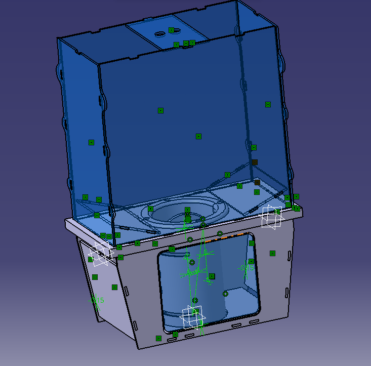
Inspiration and Sketch:

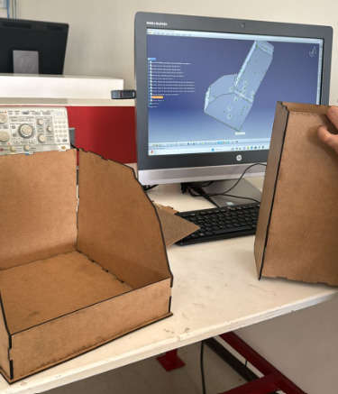
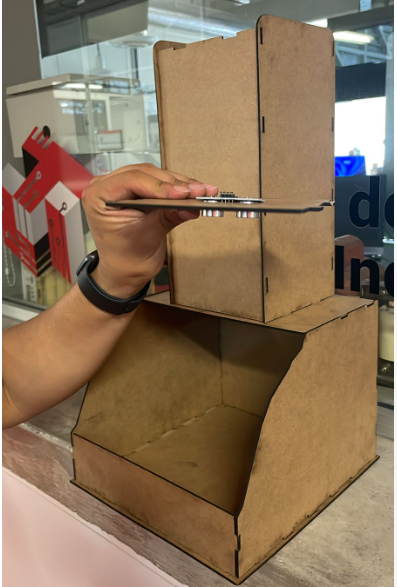
Feeder Prototype:
Introduction
preparation of a feeder based on laser cutting and 3D printing (all designed from a computer drawing program, in this case CATIA V5). which is capable of providing food to the pet at the time the user wants from a web page, just by pressing a button. In the electronics part we have a PCB where the brain of everything will be an ESP32-WROOM 32 which will be in charge of connecting with the website and carrying out the corresponding tasks, 2 servomotors are connected to this which are responsible for opening gates to They supply food.
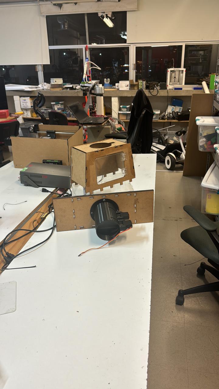
Prototype 1
Download pieces to assemble
If you want to learn more about 3D design, 3D printing, or laser cutting, you can visit my week 2,week 3 , and week 5, where I discuss these topics in more detail.
Development:
1. Servo to dispense food
In this initial approach, the design of my "Smart Paw" project works well overall, but it has some drawbacks. The kibble tends to get stuck in the 3D-printed nozzle, and the cables and the servo are very accessible to the dog, causing it to try to destroy them due to the noise the motor makes. Additionally, the base was unstable and could not support the weight of the MDF and the several kilograms of kibble, causing it to sag and fall even with glue.
Improvements:
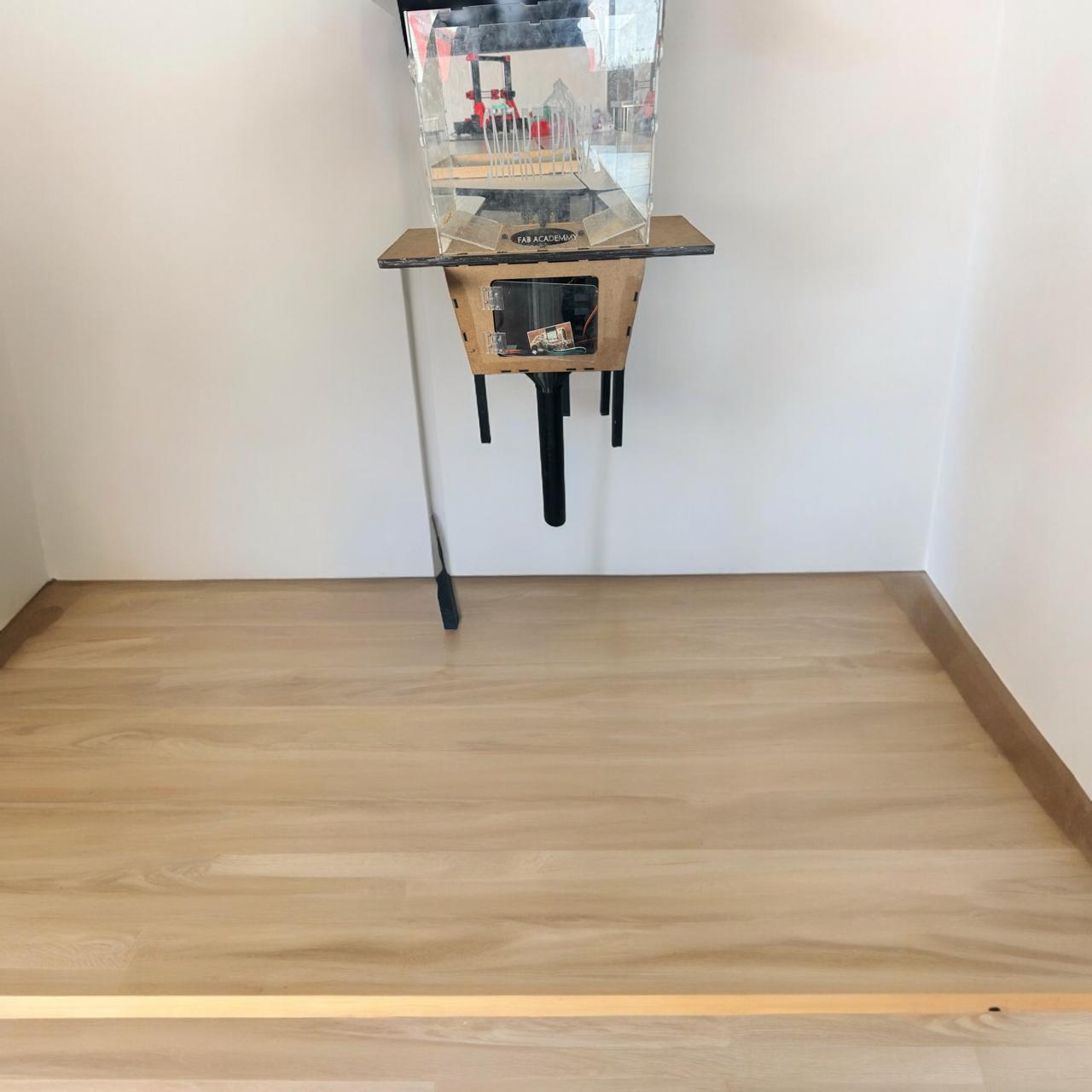
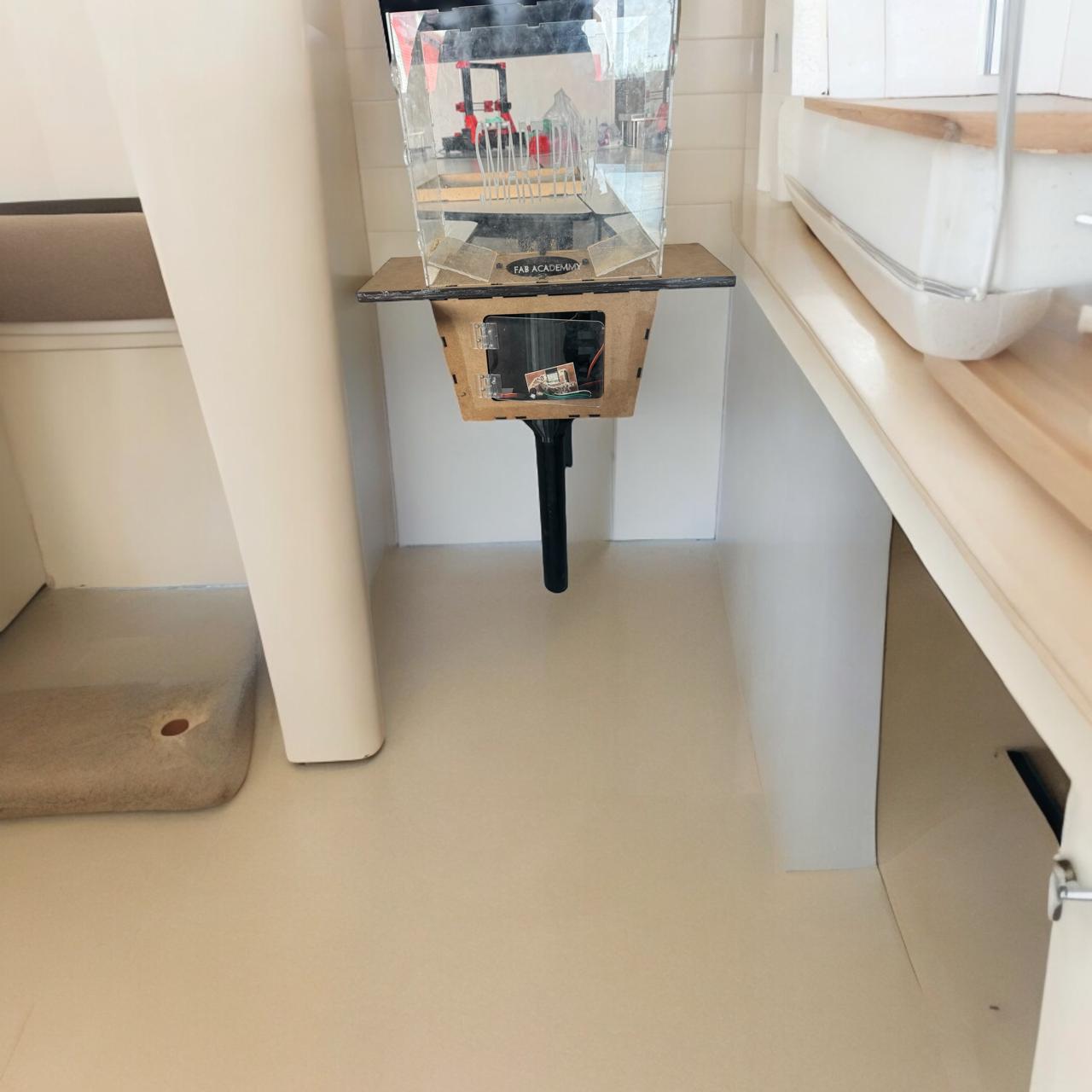
Final feeder prototype.


Components
| Quantity | Description | Cost (USD) | Photo |
|---|---|---|---|
| 1 | ESP32 | $11.11 | 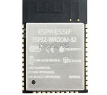 |
| 2 | Servomotor | $16.67 | 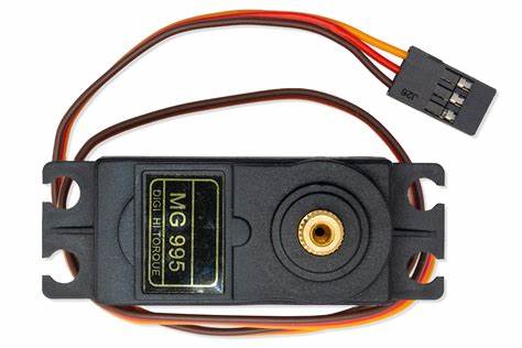 |
| 3 | Resistors 220Ω | $2.78 | 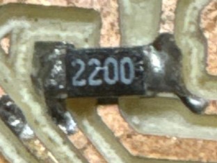 |
| 3 | Buttons | $1.67 | 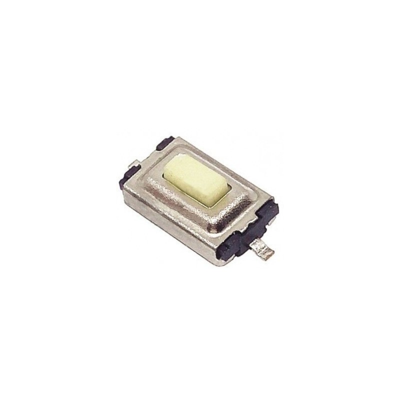 |
| 5 | jumpers | $11.11 | 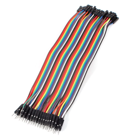 |
| 2 | Resistances 0Ω | $0.20 | 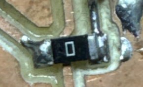 |
| 1 | Capacitors 1000uF 25V | $2.50 | 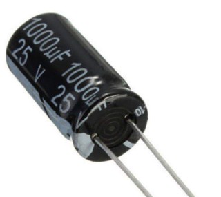 |
| 2 | Capacitors 1 µF 50V | $3.00 | 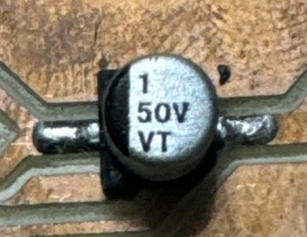 |
| 3 | Pin Header Female | $1.00 | 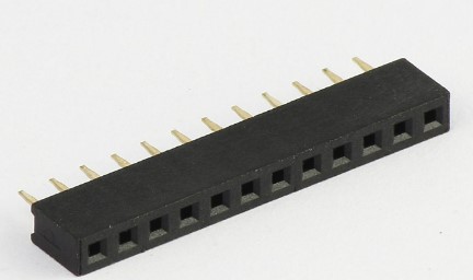 |
| 1 | AMS1117 | $2.50 | 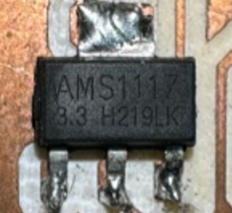 |
| 1 | USBFT232 USB | $10 | 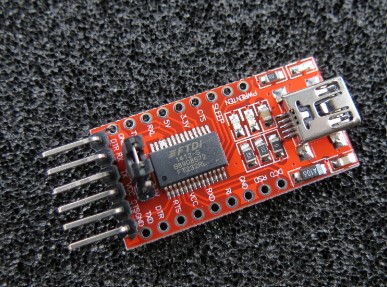 |
Processes
| Description | Cost (USD) | Photo | |
|---|---|---|---|
| 3D Printing (Approx. 0.5 kg) | $16.67 | 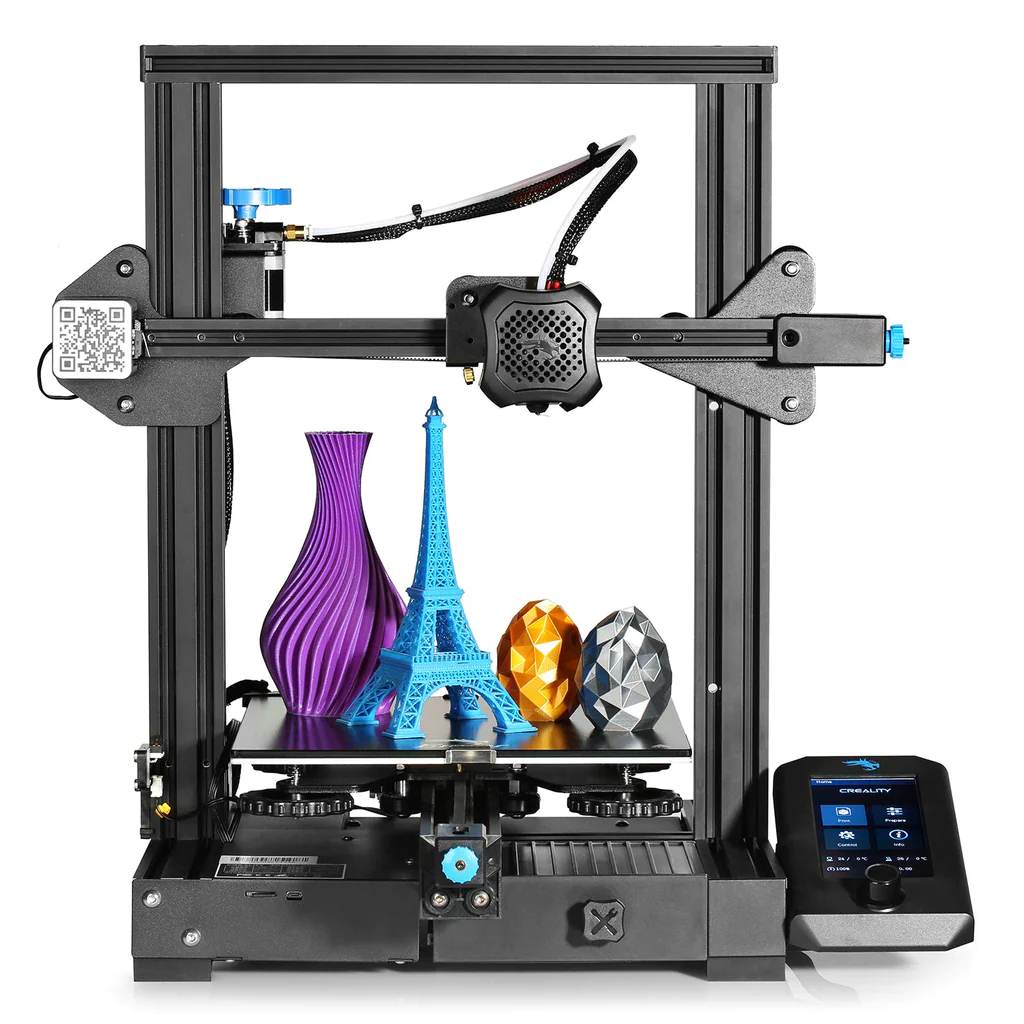 |
|
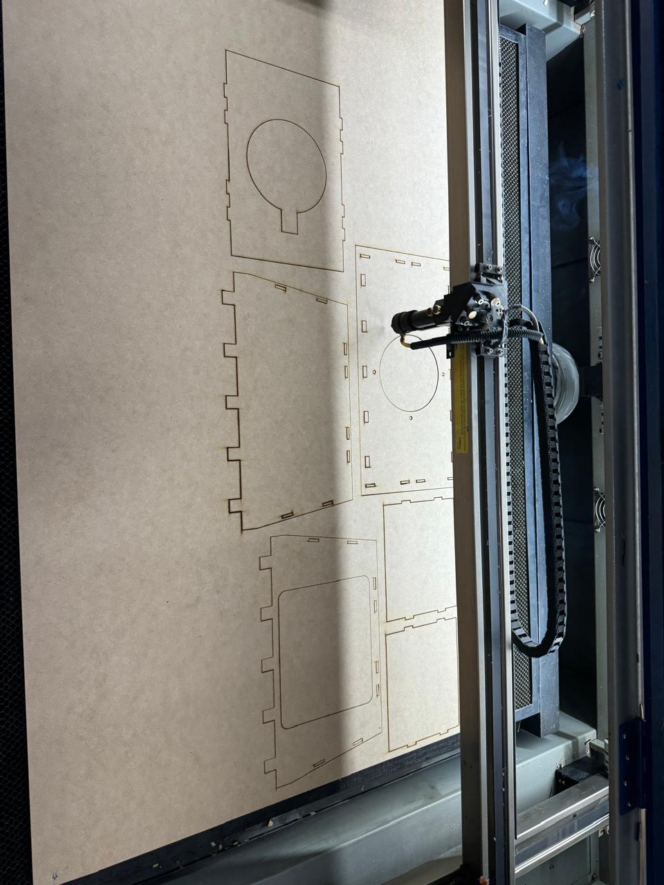
| Laser Cutting | $27.78 | 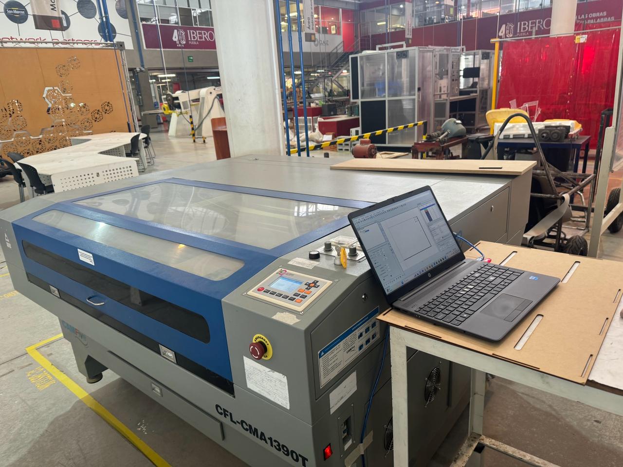 |
|
| Soldering | $5.56 |  |
|
| Copper for PCB | $5.56 |  |
|
| MDF 3mm | $10.00 |  |
|
| Acrylic 4mm | $12.00 |  |
|
PCB
This schematic represents a circuit based on the ESP32 microcontroller. Below is a detailed description of each section and component in the circuit:
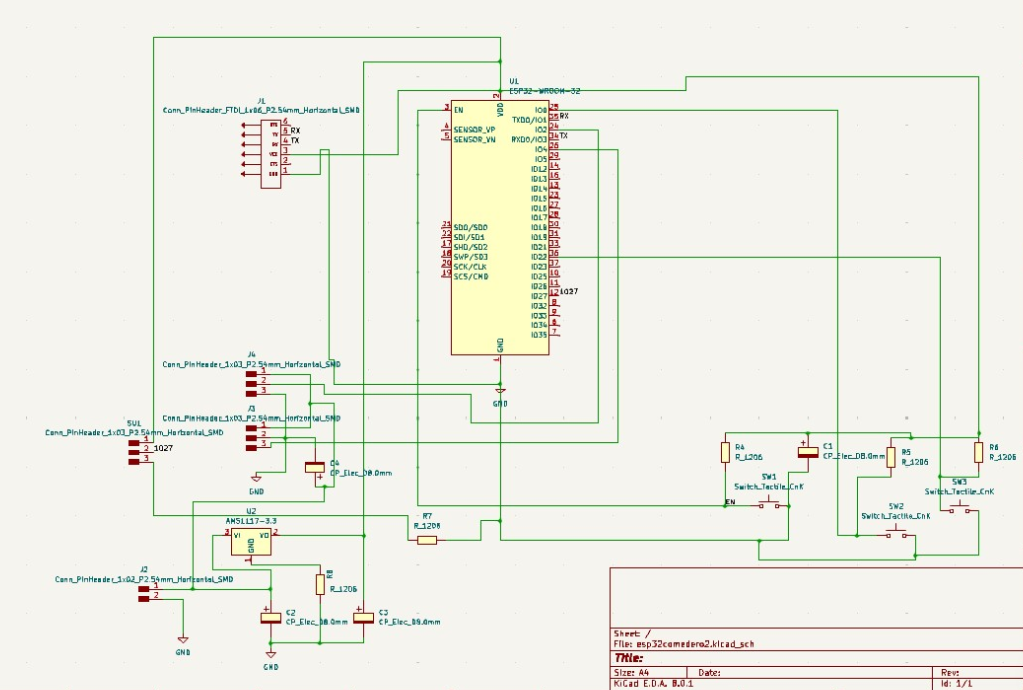
1. ESP32 Microcontroller (U1):
The ESP32 is the core of the circuit, responsible for processing and Wi-Fi/Bluetooth connectivity. The GPIO pins of the ESP32 are connected to various components and peripherals. The GPIO2 and GPIO15 pins (J2 and J3) are used to connect two servomotors, allowing their control via the ESP32.
2. TTL Programmer (J1):
The J1 connector provides an interface for programming and serial communication with the ESP32. The RX and TX pins of the ESP32 are connected here to enable data transfer.
3. Voltage Regulator (U2):
The AMS1117-3.3V regulator converts the input voltage to 3.3V, which is the operating voltage for the ESP32. This ensures that the microcontroller and other components receive a stable power supply. The capacitors (C2 and C3) around the regulator help filter noise and stabilize the output voltage, which is critical for reliable circuit operation.
4. Decoupling Capacitors:
The capacitor C1 is connected near the ESP32 and acts as a decoupling capacitor, reducing noise and stabilizing the power supply near the microcontroller.
5. Switches and Resistors:
There are three tactile switches (SW1, SW2, SW3) connected to the circuit, allowing manual interaction. These switches are connected through pull-up resistors (R4, R5, R6) to ensure the input pins do not float when the switches are not pressed. Additionally, there are current limiting and protection resistors (R7, R8) in the circuit.
6. Connectors for Servomotors:
The connectors J2 and J3 are designed for connecting two servomotors, allowing them to be controlled through the GPIO pins of the ESP32.
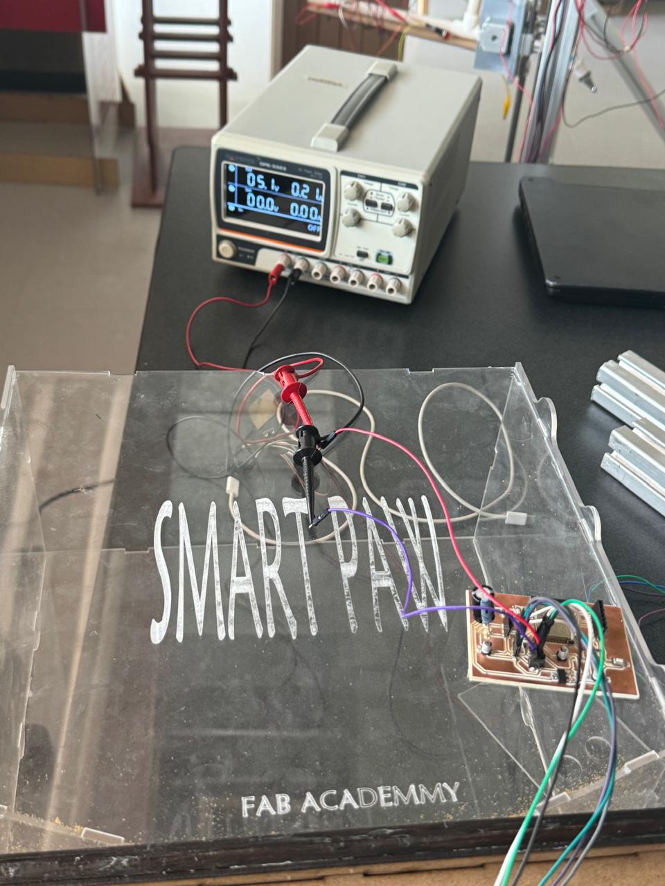
7. Power Supply Details:
The circuit is powered through an input connector (GND and VCC), which can be a battery or an external power source. This input voltage is regulated to 3.3V by the AMS1117-3.3V to ensure safe and stable operation of the ESP32 and connected components.
This design ensures that the ESP32 can efficiently control the servomotors and other peripherals with a stable power supply, programming, and communication options via the TTL programmer. If you need more details about any specific component or connection, please let me know.

Download to cut PCB
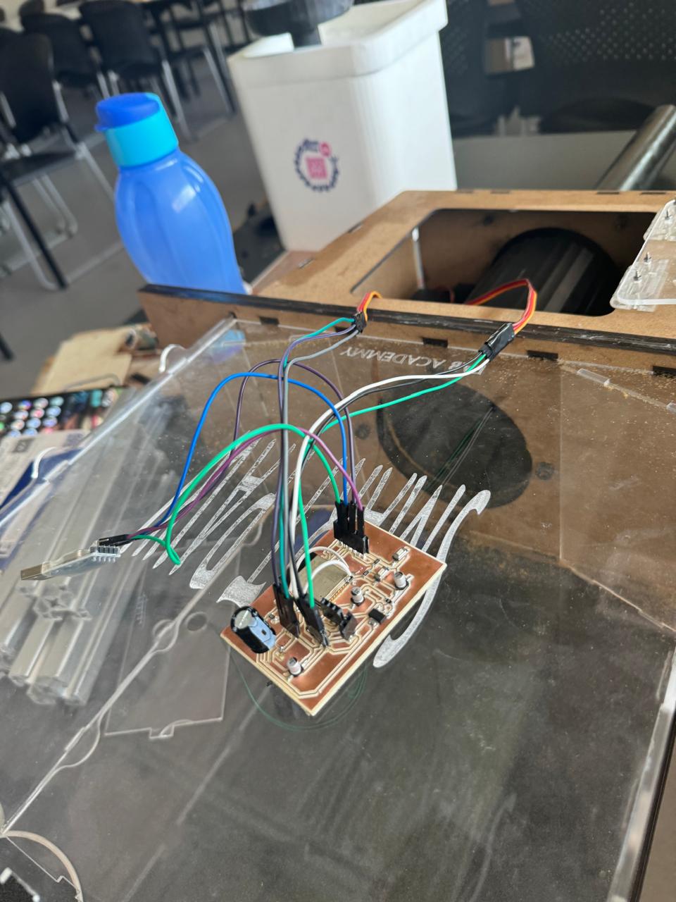
final result of pcb

ESP32 Design Improvements
The black top part of the ESP32 is an antenna. Currently, my design operates without interference, but it is important to consider some improvements to ensure optimal efficiency in the long term:
PCB Design
It is crucial to ensure that there is no copper directly under the antenna when milling the PCB. This helps to prevent signal interference and allows the antenna to operate effectively. In my current design, I have considered this aspect to avoid potential issues.
Placement
Similar to development boards, it is recommended to place the antenna outside the main area of the PCB or on the edge of the board. This minimizes obstructions and maximizes signal strength. Although my current design is functioning well, considering this recommendation can further improve performance.
Clearance
Maintaining sufficient clearance around the antenna is essential to avoid interference from other components and traces. I have tried to follow this practice in my design, but it is always good to review and ensure it is adequately met.
Integrating these points into the design can significantly improve the performance of the ESP32 antenna on my PCB. Although I currently have no interference issues, considering these improvements can be beneficial for future developments.
In the PCB, you can see soldered wires because I did not correctly account for the PWM outputs when designing it. As a result, I connected them to ports without PWM functionality. Consequently, I had to solder the traces to PWM ports manually. I implemented this solution to avoid wasting copper or other materials that could be damaged during desoldering. Once I identified the problem, I decided that this was the best solution, considering both environmental and economic impacts, and it allowed me to make the existing setup functional.
Programming
Programming of Sensors and Actuators:
Arduino Servo Motor Code Explanation
In the photo where it shows the connection to the network "frank" is because the school's internet is a private network that does not allow connecting for these types of exercises. Since I have an iPhone, it was difficult to create a shared network, so I asked a friend with Android to do it in a simpler and more practical way.
This Arduino code is designed to connect to a WiFi network, make an HTTP request, and control two servos based on the response received. Below, each important part of the code is explained:
                // Included Libraries
                #include <WiFi.h>              // Allows connection to WiFi
                #include <WiFiClient.h>       // Allows communication with the server
                #include <HTTPClient.h>       // Allows making HTTP requests
                #include <Arduino.h>          // Basic Arduino functions
                #include <ESP32Servo.h>       // Allows control of servos in ESP32

                // Global Variables
                    string web_page = "https://7b1bd7318-bc4d-4740-a62d-d7195741dcee-00-2biv5sob6tgpp.spock.replit.dev/comedero.php";
                String message = "";
                Servo myservo1;                     // Top servo
                Servo myservo2;
                int pos1 = 5;
                int pos2 = 5;
                int v = 0;
                int a = 0;

                void setup() {
                delay(10);
                Serial.begin(115200);         // Serial monitor at 115200 baud
                myservo1.attach(2);
                myservo2.attach(4);

                for (uint8_t t = 4; t > 0; t--) {
                Serial.printf("[SETUP] WAIT %d...\n", t);
                Serial.flush();
                delay(1000);
                }

                WiFi.begin("frank", "franlopez");   // Connect to WiFi network
                while (WiFi.status() != WL_CONNECTED) {
                delay(500);
                Serial.print(".");
                            }
                Serial.println("Wifi connected, my IP is");
                Serial.println(WiFi.localIP());
                        }

                void loop() {
                if (WiFi.status() == WL_CONNECTED) {
                HTTPClient http;
                message = web_page + "?get_var4=true";   // Request message
                http.begin(message);
                int httpResponseCode = http.GET();

                if (httpResponseCode > 0) {
                Serial.print("HTTP Response code: ");
                Serial.println(httpResponseCode);
                String payload = http.getString();
                Serial.println(payload);

                if (v == 1) {
                if (a == 0) {
                for (pos1 = 5; pos1 <= 90; pos1++) {
                myservo1.write(pos1);
                delay(15);
                                            }
                delay(500);
                for (pos1 = 90; pos1 >= 5; pos1--) {
                myservo1.write(pos1);
                delay(15);
                                            }
                a = 1;
                delay(500);
                                        }
                if (a == 1) {
                for (pos2 = 5; pos2 <= 90; pos2++) {
                myservo2.write(pos2);
                delay(15);
                                            }
                delay(500);
                for (pos2 = 90; pos2 >= 5; pos2--) {
                myservo2.write(pos2);
                delay(15);
                                            }
                a = 0;
                delay(500);
                                        }
                                    }

                if (v == 0) {
                pos1 = 5;
                pos2 = 5;
                myservo1.write(pos1);
                myservo2.write(pos2);
                                    }
                                }
                else {
                Serial.print("Error code: ");
                Serial.println(httpResponseCode);
                                }
                http.end();   // Terminate connection
                            }
                delay(500);
                        }
Detailed Explanation
Included Libraries: The code includes several essential libraries. #include WiFi.h> allows connection to WiFi networks, #include WiFiClient.h> allows communication with the server, #include HTTPClient.h> allows making HTTP requests, #include Arduino.h> includes basic Arduino functions, and #include ESP32Servo.h> allows control of servos on the ESP32.
Global Variables: Several global variables are defined, such as
web_page which stores the HTTP request URL, and
myservo1 and myservo2 which are Servo objects for controlling two servomotors.
Also, pos1 and pos2 are initial positions for the servos,
and v and a are variables for the program logic.
Setup: The setup() function initializes the serial connection to 115200 baud, connects the servos to pins 2 and 4, and establishes the WiFi connection to the "frank" network with the password "franlopez". If the connection is successful, it prints the local IP address.
Loop: In the loop() function, if the device is connected to WiFi, an HTTPClient object is created and a GET request is made to the specified URL. Depending on the HTTP response, the code controls the servos based on the value of v. If v == 1, the servos move to specific positions with delays between each movement. If v == 0, the servos reset to their initial positions. Finally, if there is an error in the HTTP response, it prints the error code.
Download code
system integration
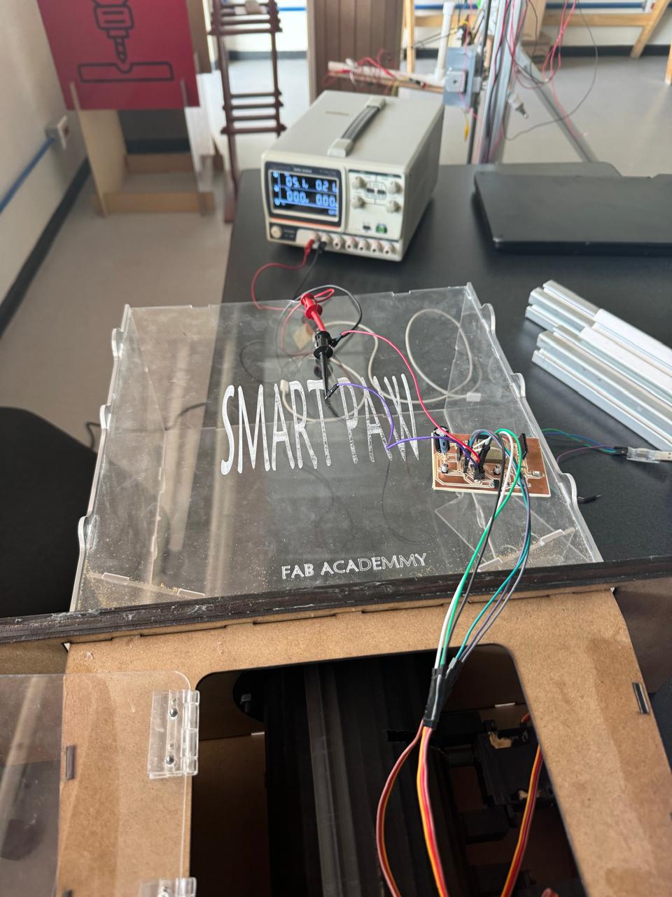
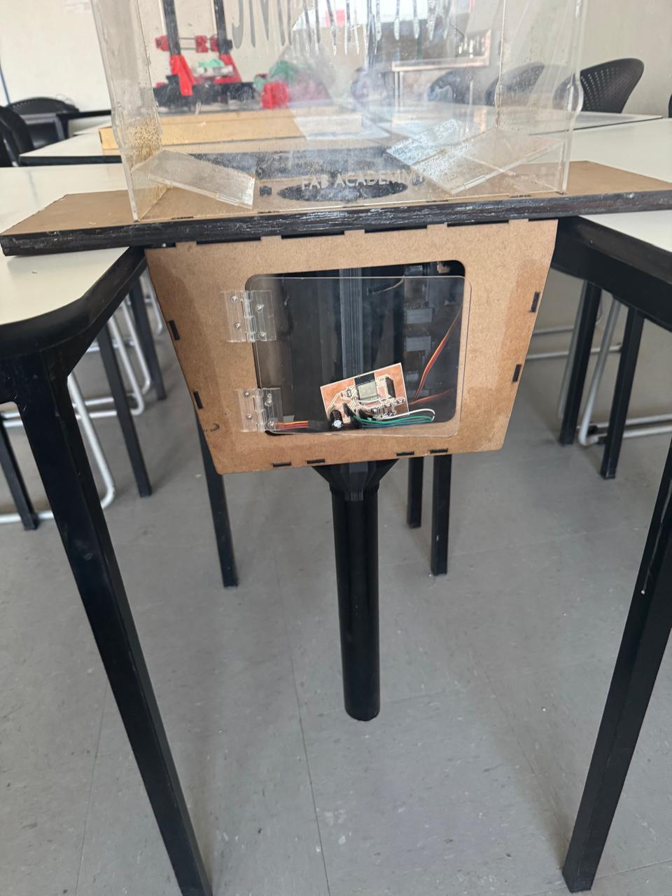
In this part, I integrated everything in a way that includes a door to clear any food blockage or electronic failure. Additionally, since it is a prototype, its internal components can be seen so that people can appreciate them.
Final Feeder prototype.