Computer controlled cutting
Linked to the group assigment page
personal learning
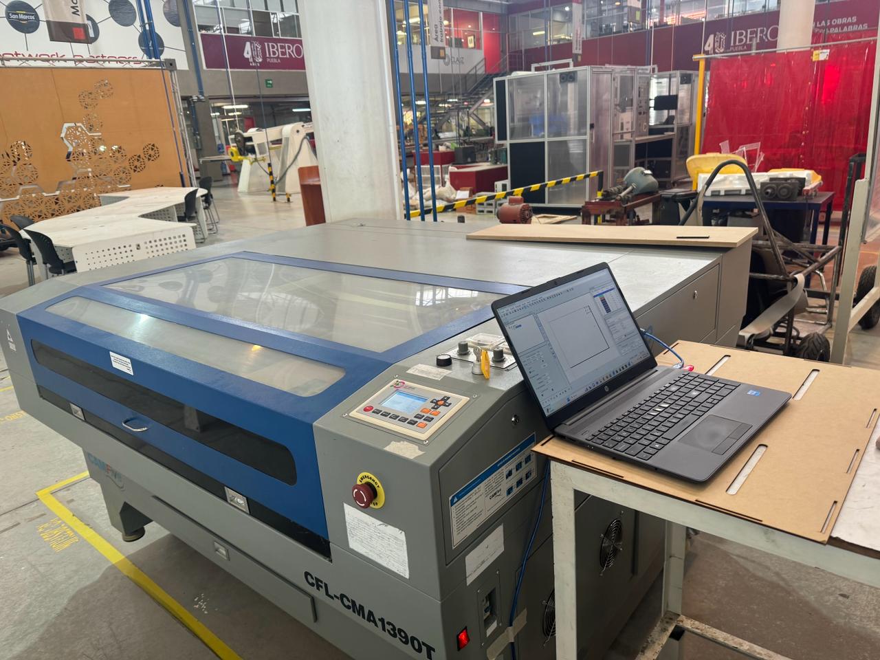
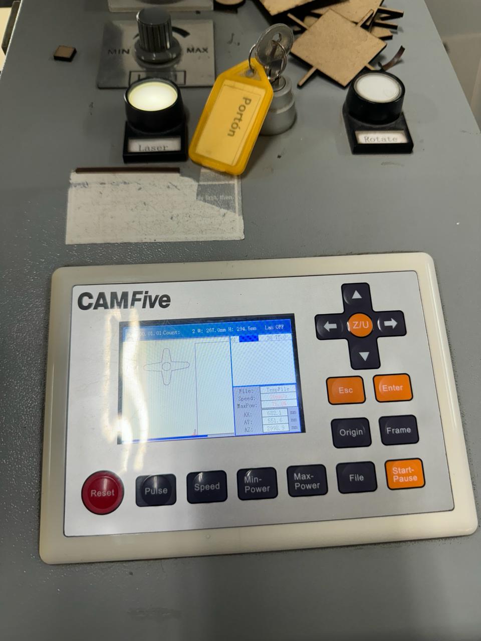
During this week, I participated in a laser cutting orientation session and used a CamFive machine, model CFL-CMA 1390T
prototype idea
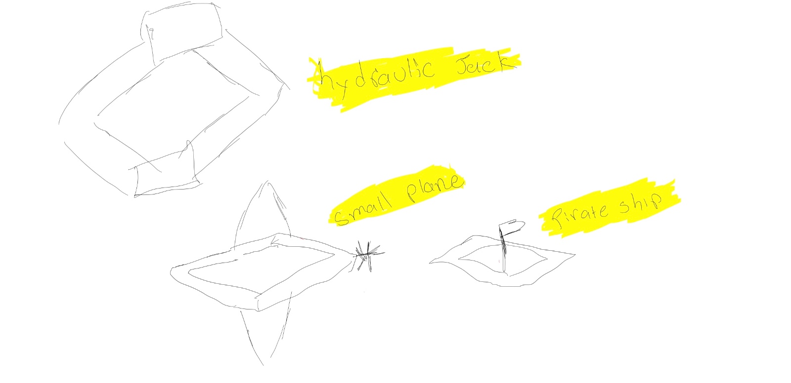
In this section, I had a brainstorming session and sketched out all of the ideas in pencil. While only some of these ideas were implemented, the sketches of the other potential ideas are retained for future development.
Parametric
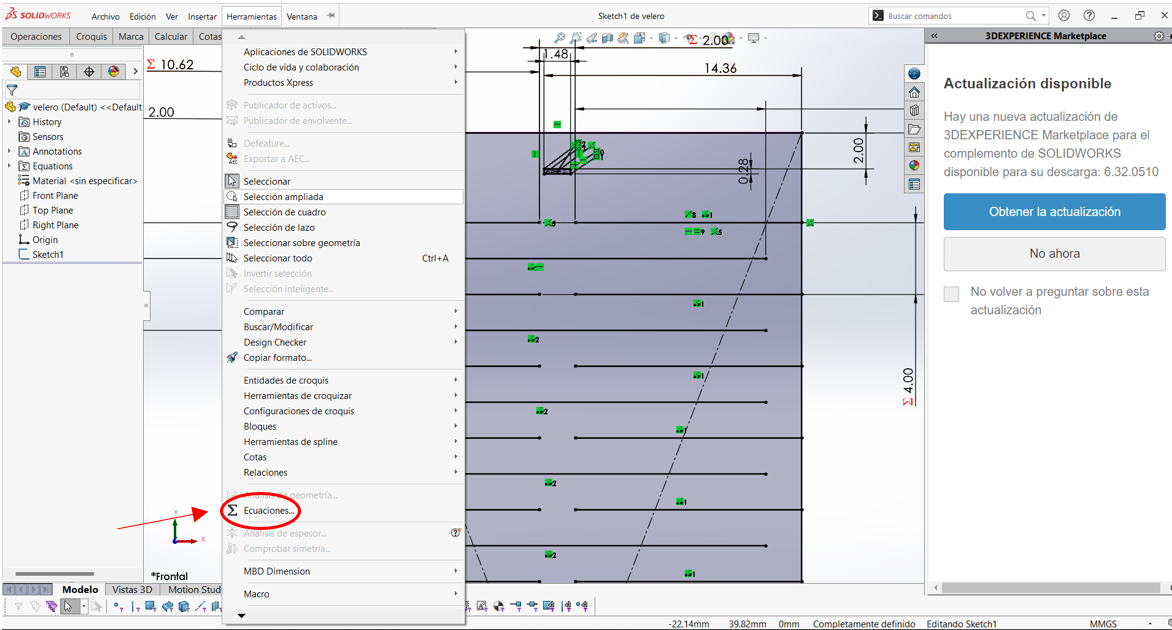
All the parts attached in this project were created and designed in SolidWorks. Furthermore, they are parameterized for the kit, allowing their dimensions to be changed at any time using equations. I have attached an example of just one of the parts due to space and file size constraints.
It is worth mentioning that 3mm MDF was used, and a kerf of 0.2
Using 3mm MDF and Calculating Kerf for Precise Assemblies
What is Kerf and Why is it Important?
In this project, I used 3mm MDF to create pieces that fit together. One of the most important considerations when working with laser cuts is the "kerf". The kerf is the amount of material removed during the cut, and in this case, I determined the kerf to be 0.2mm. This value is crucial to ensure that the pieces fit precisely.
Why Use a 0.2 Kerf?
After performing several tests and adjustments, I found that a 0.2mm kerf is ideal for laser cuts in 3mm MDF. This value ensures that the pieces assemble correctly without being too tight or too loose.
How to Calculate and Apply Kerf in Designs
Steps to Calculate and Adjust the Kerf:
- Measure the Kerf: I performed test cuts and measured the difference between the original design dimensions and the cut pieces to determine the exact kerf.
- Adjust Dimensions:
- For Tight Fits: Subtract the kerf from the slot dimensions.
- For Loose Fits: Add the kerf to the tab dimensions.
Practical Example:
Original Tab Dimension: 10mm
Determined Kerf: 0.2mm
For a tight fit:
Adjusted Slot Dimension: 10mm - 0.2mm = 9.8mm
For a loose fit:
Adjusted Tab Dimension: 10mm + 0.2mm = 10.2mm
Additional Information Based on the images
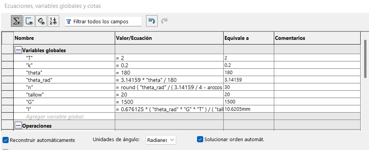
The images shows how I configured global equations to adjust the dimensions of the pieces, taking into account the kerf. Here are the details of the parameters and their meanings:
- T (Material thickness): Thickness of the material, in this case, 2mm.
- k (Kerf): 0.2mm, the kerf value used to compensate for the material removed during the cut.
- theta: Total bend angle in degrees (180 degrees).
- theta_rad: Bend angle in radians, calculated as (π * theta) / 180.
- n: Minimum number of material columns.
- tallow: Allowed torsional stress in MPa (20 MPa).
- G: Torsional modulus of the material (1500 MPa).
- I: Torsional modulus, calculated using a specific formula based on the previous parameters.
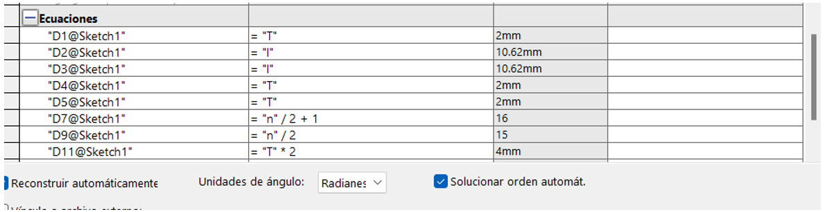
The feature and dimension equations automatically adjust the dimensions of the pieces considering the kerf and other relevant factors, ensuring a precise and functional design.
Proper use of kerf is essential for precise assemblies in digital fabrication. With 3mm MDF, a 0.2mm kerf is effective. Adjusting dimensions according to the kerf ensures that parts fit correctly, whether for a tight or loose fit. This improves the final product quality and optimizes cutting precision. The global equations and variables helped me automate this process, ensuring all parameters are considered for precise and efficient design.
If you want to learn more about calculating kerf or the equations used, you can visit our group page here.
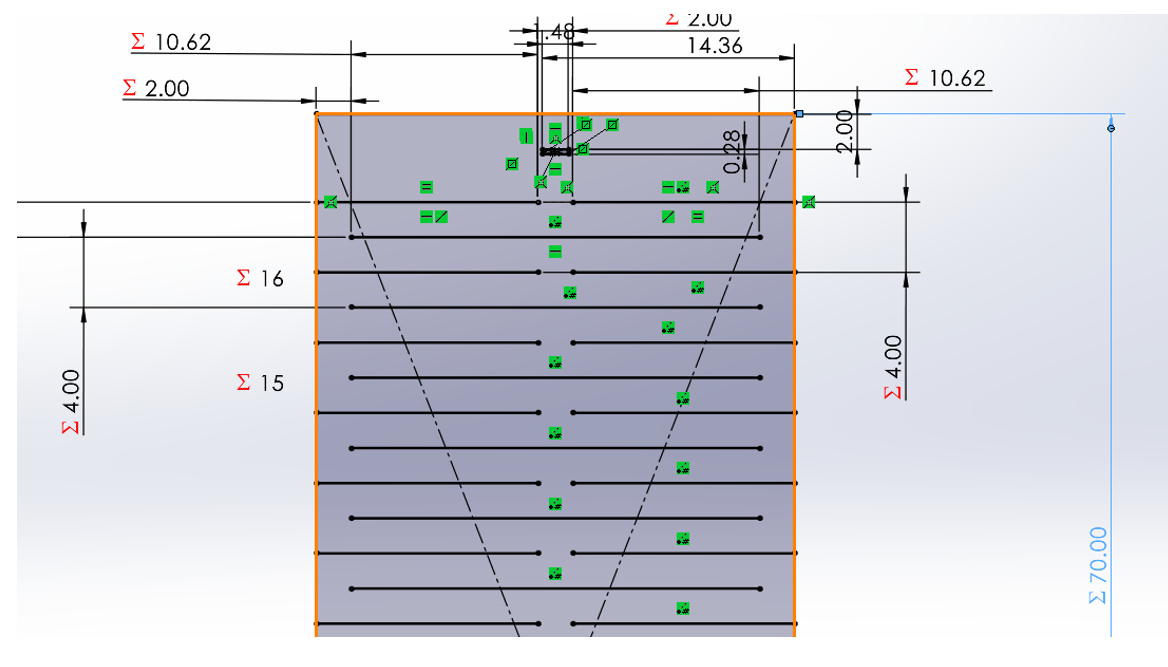
The images show step-by-step the use of equations and variables, and finally, an image of the sketch is provided.
My first laser cut
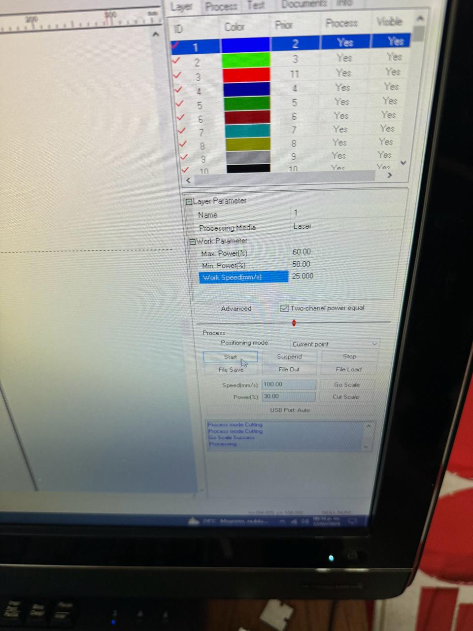
The machine was configured with the following parameters: max power 60, min power 50, work speed 25. Additionally, we calibrated the Z-axis from 5 to 6 mm from the laser to the piece. Once the pieces were loaded into the program, we clicked "go scale", and if it worked, we proceeded to cut with the laser at maximum power and turned on.

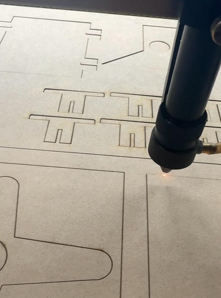
In this section, the cuts of the pieces and the final result will be presented. At the end of the page, the DXF files used for the cutting will be attached.
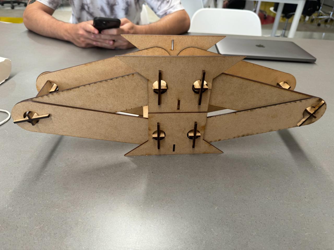
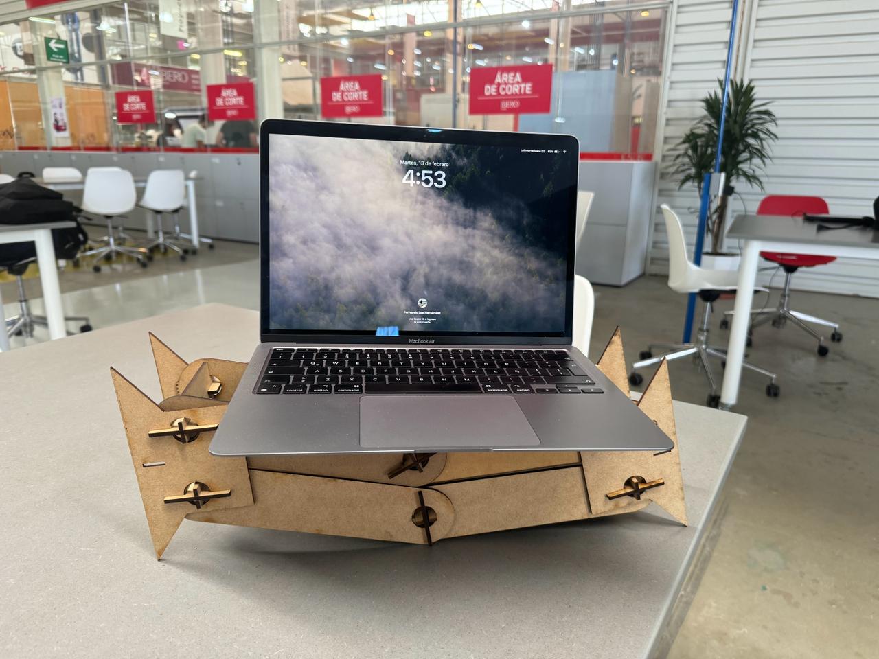
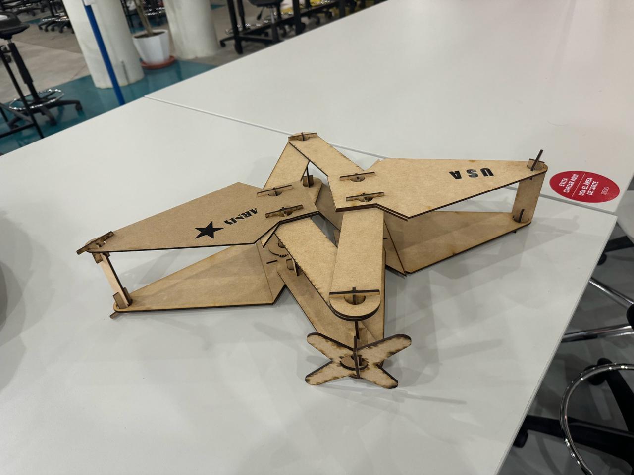
Assembly of Parts
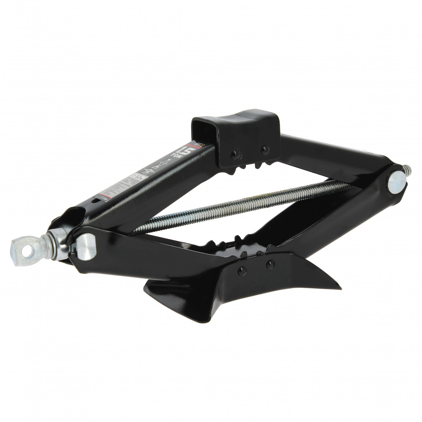
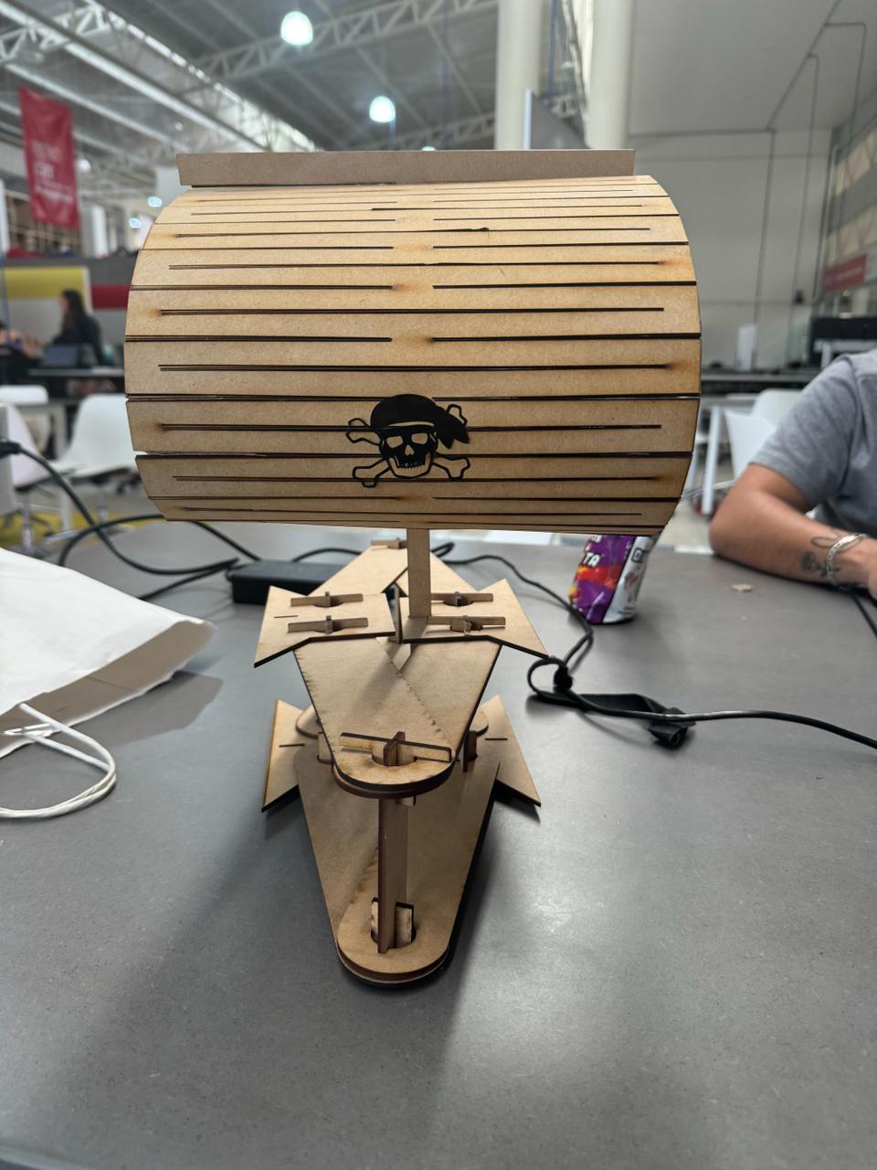
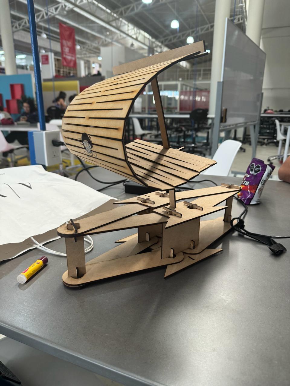
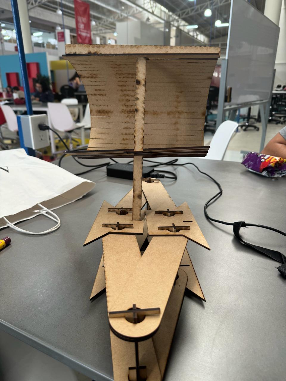
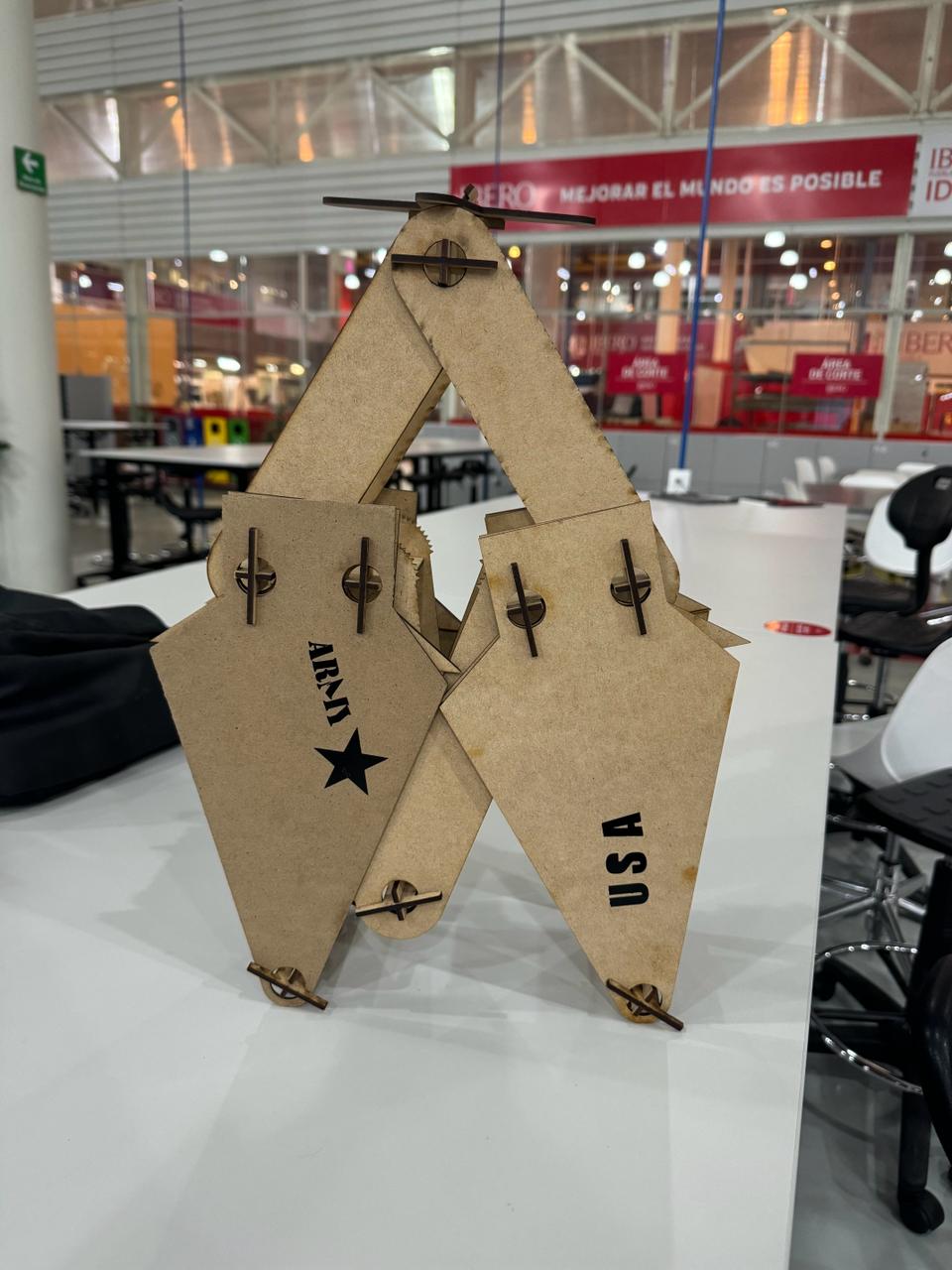
In this section, we took the pieces and built whatever came to mind. In this case, I've included an airplane, a hydraulic jack, and a pirate ship.
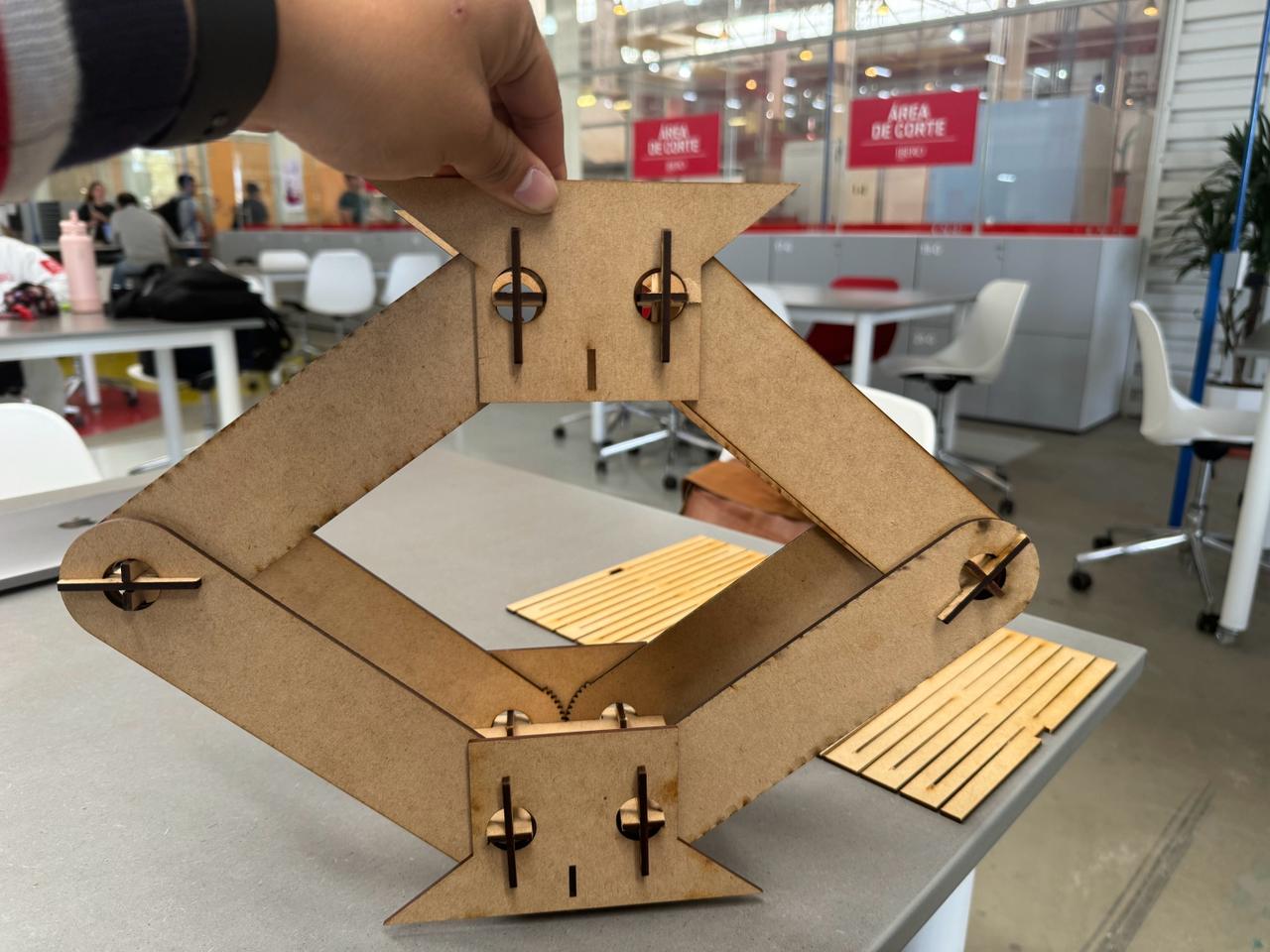
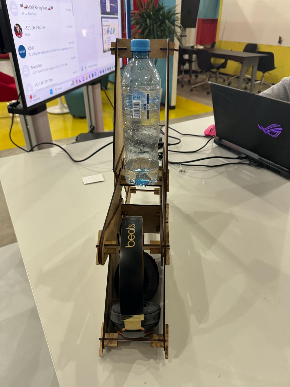
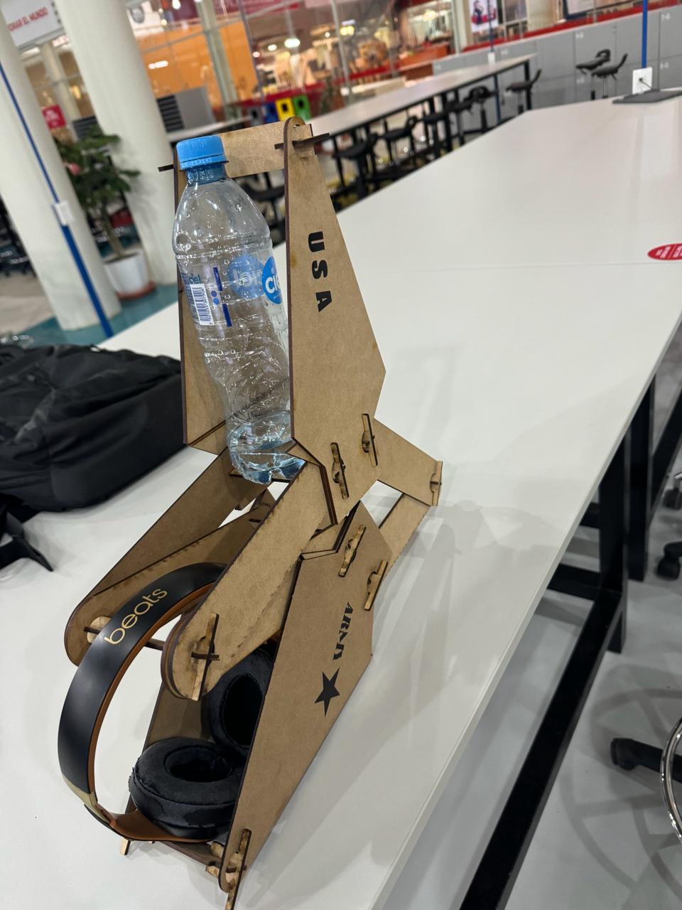
others ideas
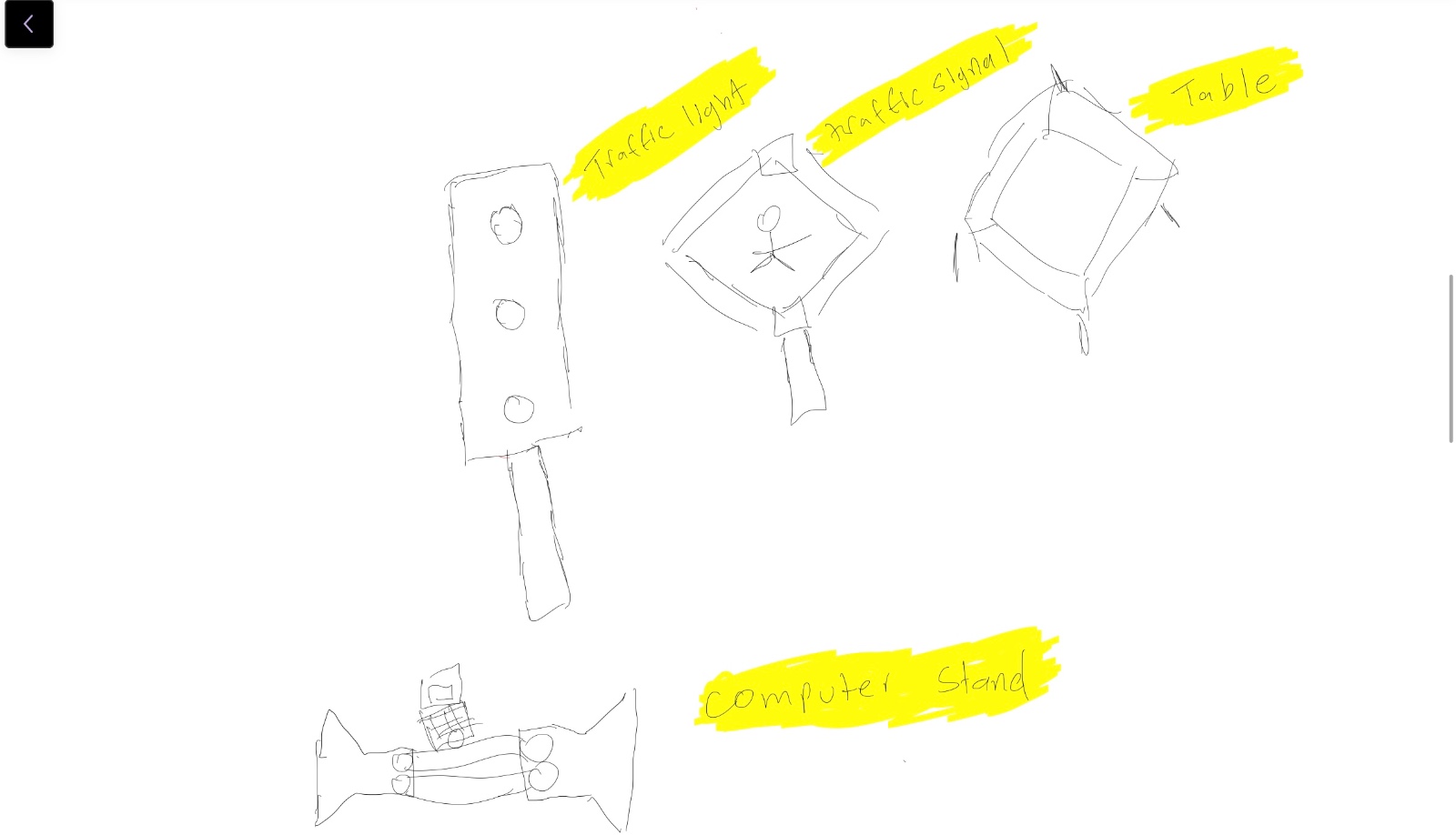
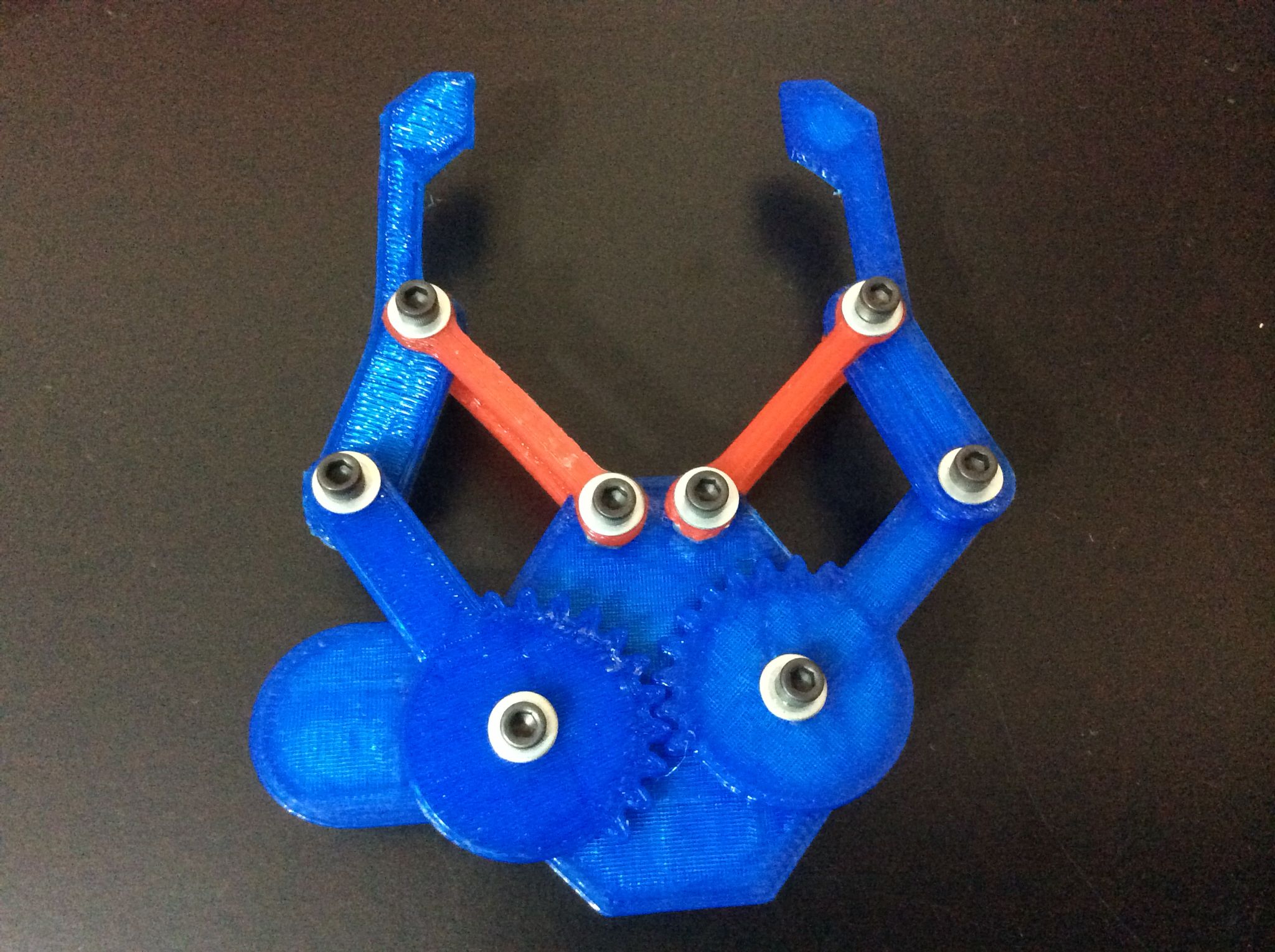
These are other ideas that I didn't initially think of, but they came to mind as I assembled the pieces. Just like these, there are more ideas; the limit is your imagination.
Files DXF
- Front propeller
- Gear
- Flag stand
- Base support
- Square bracket
- T-joints
- Ship flag
- Rectangular bracket
- Airplane wing
Files CAD PART
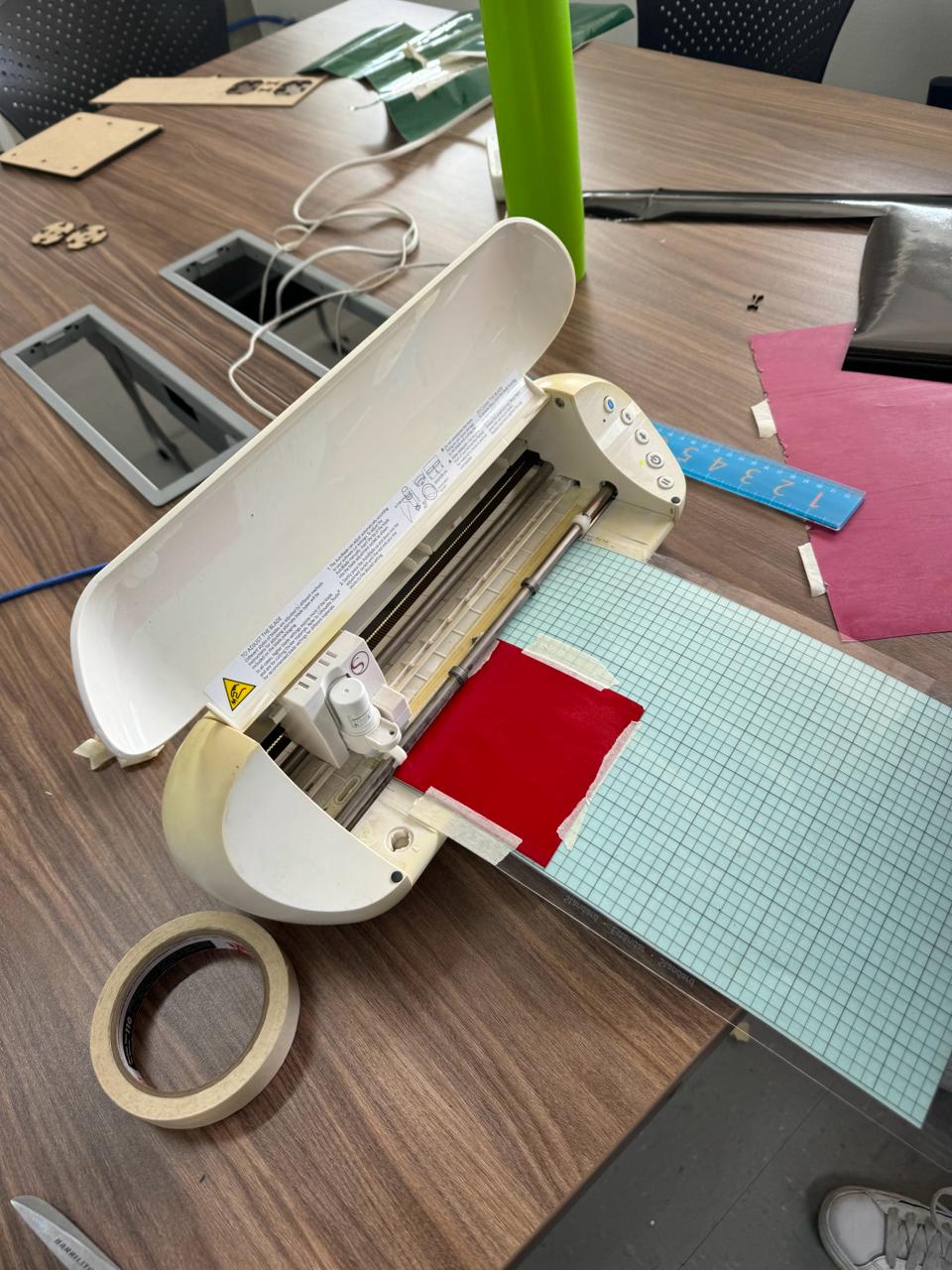
vinyl cutting
The CS-923 laminator applies foil using thermal transfer onto paper and cardstock up to 9 inches wide. You print your design in black and white with a laser printer, place it in the paper folder of the laminator, place the foil over the printed area, and apply heat. The foil adheres only to the areas with ink. It does not require connection to other devices to function.
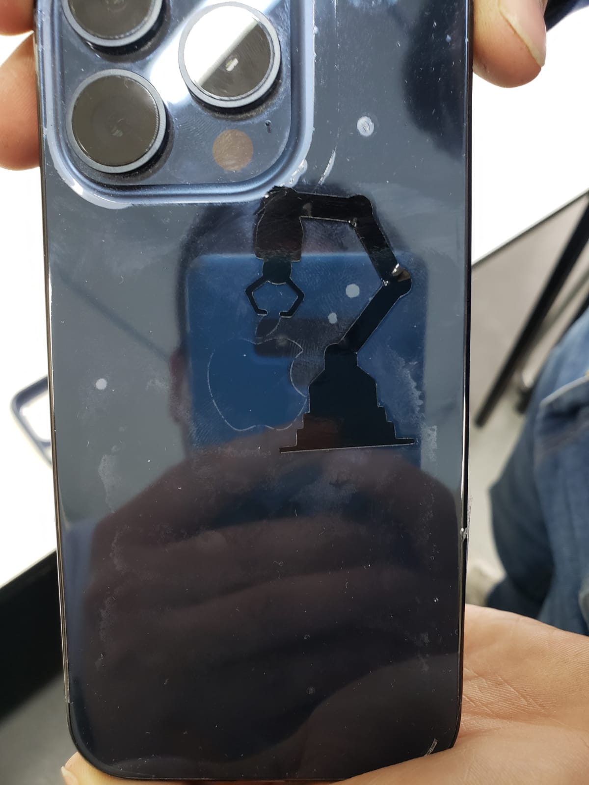
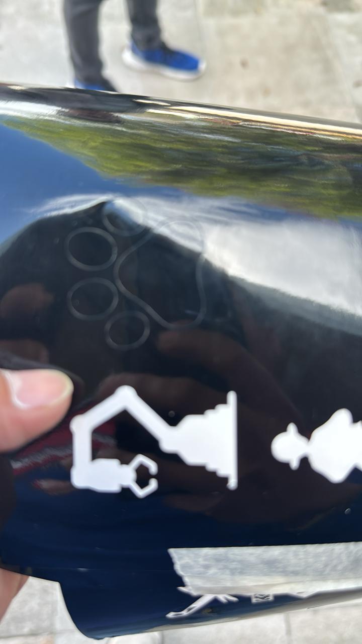
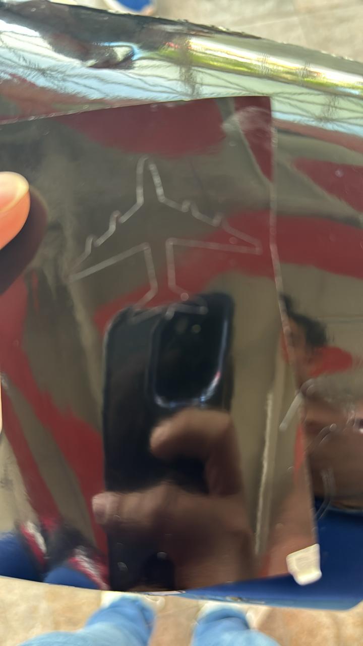
In this vinyl part, we used PNG images and then imported them into the program silhouette studio to execute the cutting. The following images show the result, and the video demonstrates the process of creating them.
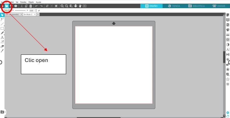
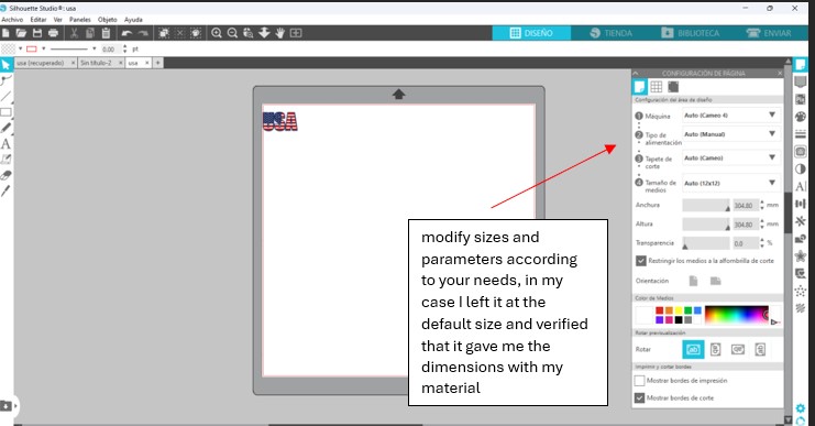
- We download the "Silhouette Studio" program
- We open it on the computer and accept the terms.
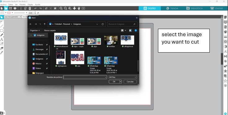
- We load the image in PNG and place it on the top left edge.
- We send it to print with the "Print" button.
- And we waited for the image to be processed.
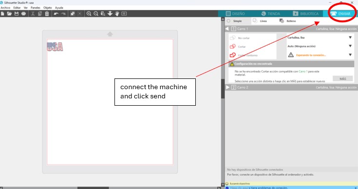
- Cut a vinyl square and insert the grid into the machine with the buttons.
- Connect the device to our computer
- Connect the device to our computer.
- And stick it on a solid surface, for textiles you need heat.