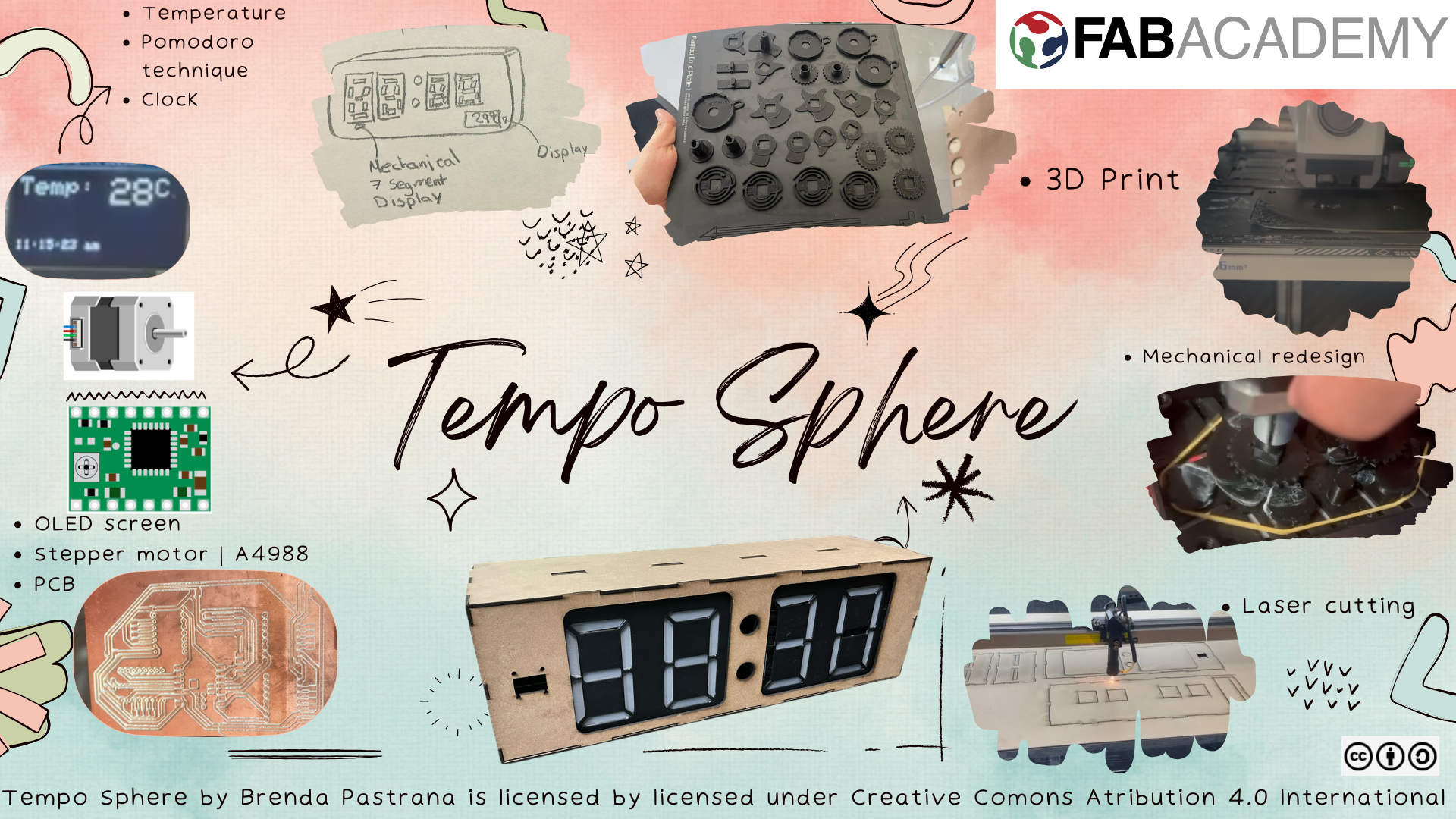
TempoSphere
What does it do?
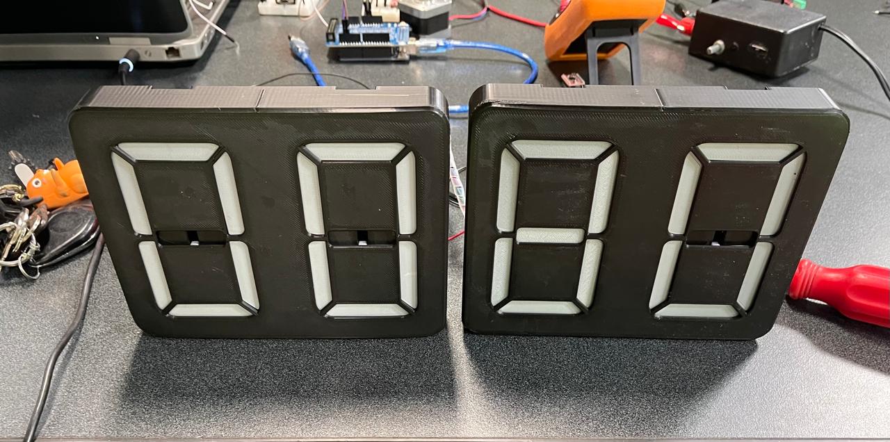
Clock with a Pomodoro timer and weather
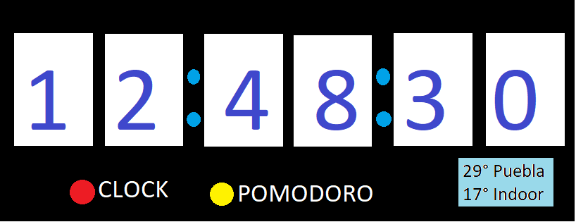
The idea of this project is to have a clock with different functionalities so that you can better organize yourself with the Pomodoro Technique. The concept is that with a button, you can switch between clock function and the technique. It would also feature a screen displaying the weather.
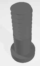
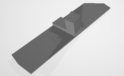
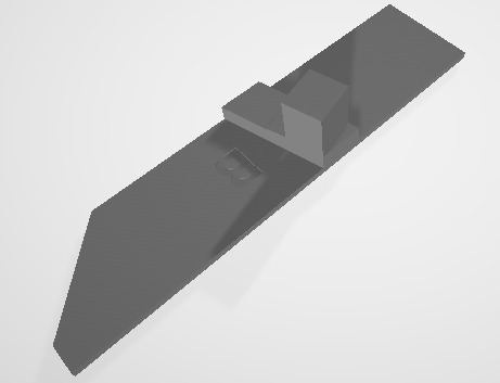
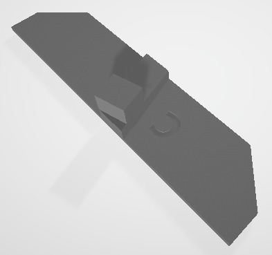
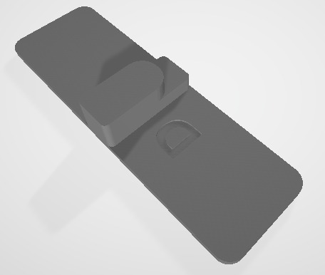
Previously, the idea was to use one motor for each numeric segment, totaling 42 motors for the clock, but this was clearly not practical. After some research, I found that mechanical 7-segment displays exist. I used one of these as a test, but its design required manually pressing a button to change the numbers. I decided to improve this model so that it has better functionality and can be adapted to implement one motor, allowing the clock to work.
Sketch
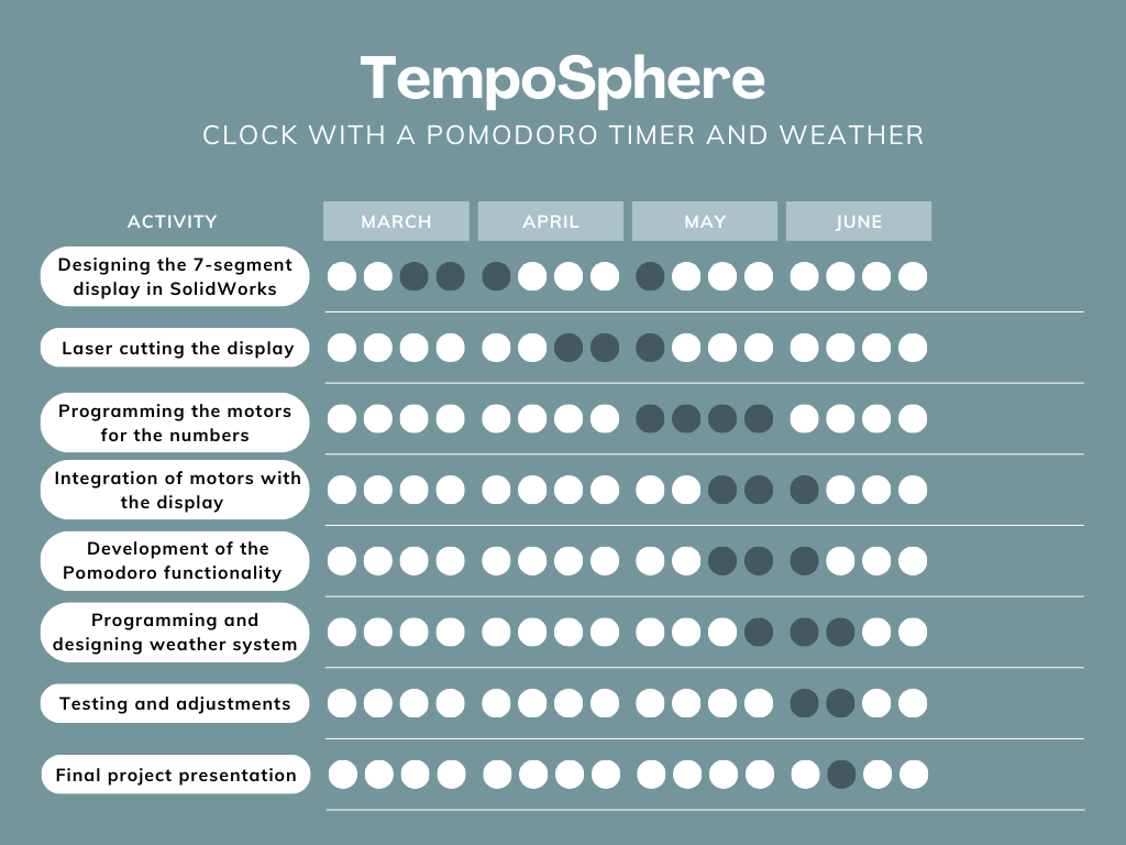
Schedule
Research
The Pomodoro Technique is a time management method developed by Francesco Cirillo in the late 1980s. It involves breaking work into intervals, traditionally 25 minutes in length, separated by short breaks. The technique aims to improve productivity by promoting focus and reducing the impact of distractions. Named after the Italian word for 'tomato' (pomodoro) due to the use of a tomato-shaped kitchen timer by Cirillo during his university years, the Pomodoro Technique has gained popularity as a simple yet effective approach to managing time and tasks.
Who’s done what beforehand?
I haven't found anyone who has made a mechanical clock with the Pomodoro method. What I have seen recently is that people have been designing mechanical 7-segment displays. For example, a guy who calls himself JBC Creative uploaded a mechanical 7-segment display. Rack Driven 7 Segment Display, but in my opinion, it is too wide, and he sells his design. Later, he joined six of these to make a clock that moves with motors. After researching more to understand the functioning of the gears, I noticed that the same guy uploaded an even thinner display, but he hasn't shared that design Mecanical 7 Segment Display. However, by investigating more on the internet, I found a free-use 7-segment display by the author Flower-3D, although his design is manual, meaning if you want to change the number, you have to press a button yourself. 7 Segment Mechanical Counter
There are some problems with the design of Flower-3D, for example, the segments do not completely hide or at certain points, the numbers are not fully visible because the gears did not move correctly.

What did you design?
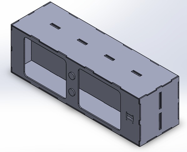
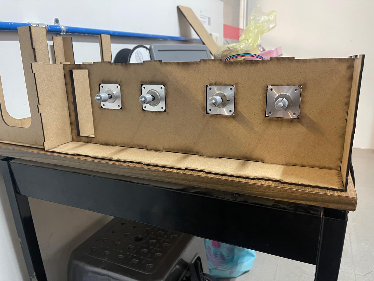
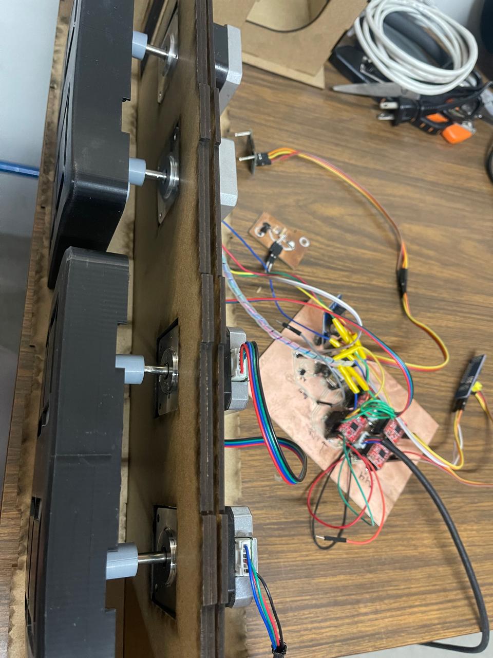
I designed the casing to hold everything in MDF. I also designed the PCB to control all the motors and sensors used.
What materials and components were used?
- PLA for 3D printing the mechanical displays and casing.
- MDF for the casing.
- NEMA 17 stepper motors.
- A4988 stepper motor driver modules.
- Xiao ESP32C3 microcontroller.
- PCF8574 I2C GPIO Expander Module.
- OLED screen.
- RTC DS3231 module.
- Button.
- 220 ohm resistors.
Where did they come from?
Materials such as the Xiao ESP32C3, PLA, and MDF were provided by FabLab Puebla. The OLED screen and motors were sourced from local suppliers in Puebla, or alternatively, they were acquired through online stores like Mercado Libre and Amazon
How much did they cost?
Materials List
| Material | Quantity Used | Supplier | Unit Cost (USD) | Total (USD) |
|---|---|---|---|---|
| NEMA 17 Stepper Motor | 4 | Steren | $13.39 | $53.56 |
| A4988 Stepper Motor Driver Module | 4 | Mercado Libre | $3.23 | $12.92 |
| XIAO ESP32C3 | 1 | Amazon | $19.99 | $19.99 |
| RTC DS3231 | 1 | Mercado Libre | $4.64 | $4.64 |
| Total | $91.11 |
What parts and systems were made?
- Mechanical 7-segment displays.
- Casing for housing the components.
- Circuit boards for the control system.
- Integration of all parts into a functioning clock and timer.
What processes were used?
- 3D printing for the mechanical parts and casing.
- Laser cutting or router cutting for the casing.
- PCB manufacturing.
- Programming the microcontroller to control the displays and handle timekeeping, Pomodoro timing, and weather display.
What questions were answered?
- How to make a better mechanism performance for the 7-segment display?
- How convenient is it to 3D print the parts? Is laser cutting more convenient?
- What speed can the mechanism withstand?
- How difficult will it be to establish communication with an API to get the location, local time, and weather?
What worked? What didn’t?
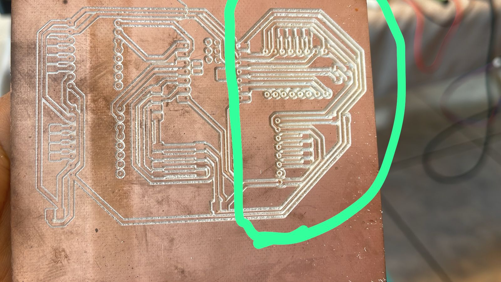
The parts that didn't work are as follows: at the beginning, I designed a PCB without conducting tests, but I never used it because the CNC ruined some of the tracks. Additionally, when testing the programming, I changed the pins and the way some things were connected because, with the Xiao ESP32, when trying to connect the motors to pins D6 and D7, they simply didn't work, so I opted to use a pin expander that communicates via I2C.
Another part that didn't work was that at the beginning of the project, I had the idea of moving each segment of each number with a servo motor, but in the end, it would require 28 servo motors and 28 pins just to program them. Therefore, I chose the design of a mechanical display that moves the 7 segments with just 1 motor.
How was it evaluated?
- Function as a clock
- Function as a Pomodoro timer
- Switch between clock and Pomodoro timer modes
- Display seems the wheather
License Choice
Open Source License
- Motivations: Select an open license to contribute to collective knowledge, facilitate learning, and encourage innovation within the maker community.
This work is licensed under a
Creative Commons (4.0 International License)Attribution-ShareAlike
✖ | Sharing without ATTRIBUTION
✔ | Remix Culture allowed
✔ | Commercial Use
✔ | Free Cultural Works

7-Segment Display Clock Instructions
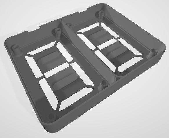
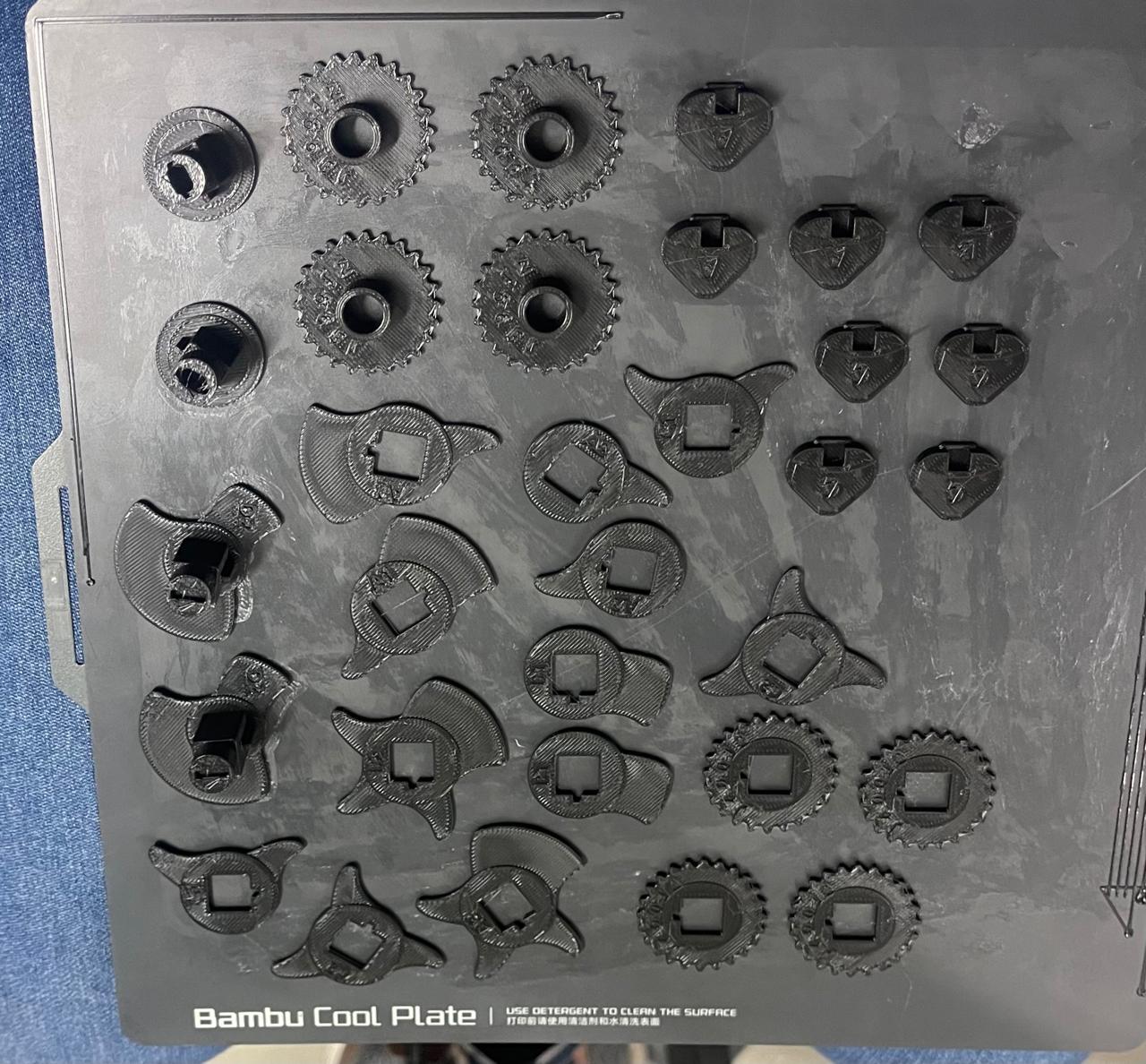
To create the clock, you will need to download the 7_Segment_Display.zip file for the 7-segment display, unzip it, and 3D print the following parts (with quantities in parentheses):
3D Printed Components:
- (2) - BODY_2-DIGIT_v2.1_standardDepth
- (4) - SEG_PLATE
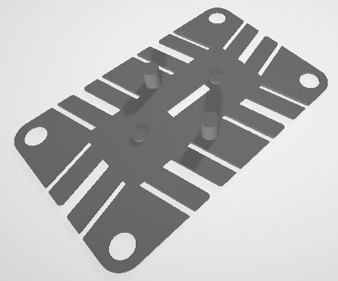
- (4) - MID_PLATE
- (16) - SCREW_v2.1
- (8) - SEG A
- (8) - SEG B
- (8) - SEG C
- (4) - SEG D
- (8) - FOLLOWER A
- (8) - FOLLOWER B
- (8) - FOLLOWER C
- (4) - CAM A1
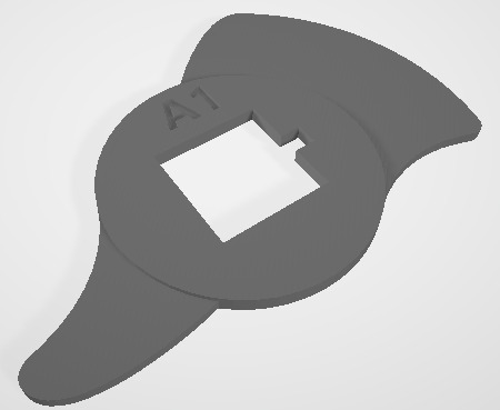
- (4) - CAM A2
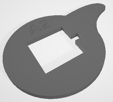
- (4) - CAM B1
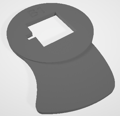
- (4) - CAM B2
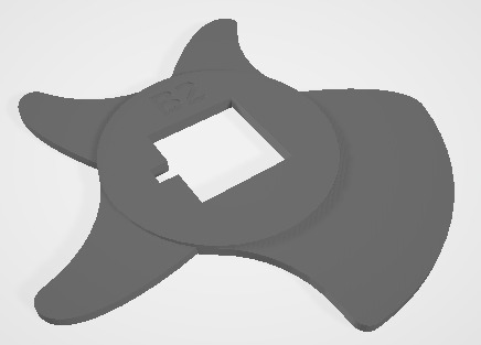
- (4) - CAM C1
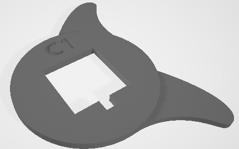
- (4) - CAM C2
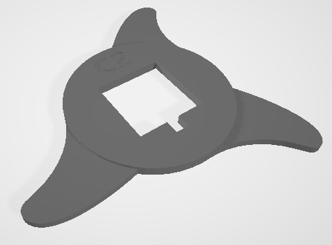
- (4) - CAM D1
- (4) - CAM D2
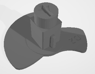
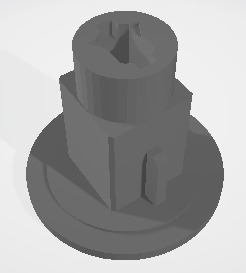
- (8) - STACK_GEAR
- (8) - SYNC_GEAR
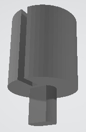
- (4) - Coupling for direct motor connection
Download the zip here 7_Segment_Display.zip
Material and Print Settings:
- Material: PLA
- Infill: 100%
- Layer Height: 0.2mm
- Supports: No
- Based on a 0.4mm nozzle
Non-3D Printed Components:
- (8) - Type #19 rubber band (2mm x 90mm)
- (16) - Type #31 rubber band (3mm x 60mm)
- (8) - Type #19 rubber band (2mm x 90mm)
- (16) - Type #31 rubber band (3mm x 60mm)
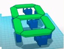
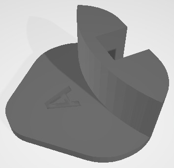
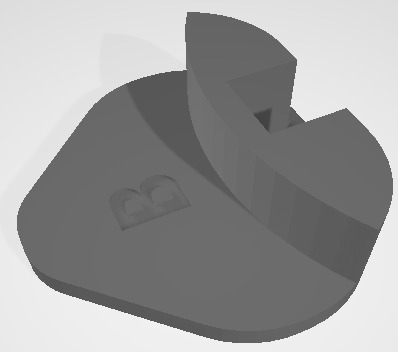
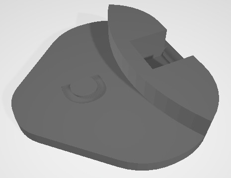
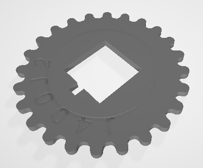
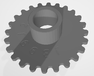
To assemble each mechanical 7-segment display, you can follow the Flower-3D tutorial. Keep in mind that you only have the parts I provided for download 7_Segment_Display.zip, and they are not the same quantity as explained in the video. You will finish assembling when you reach minute 9:32 of the video by placing the screws in the corresponding holes. Another important point is the way the bands are placed for the segments. In my design, you use 3 bands to reduce resistance. It should look like this:
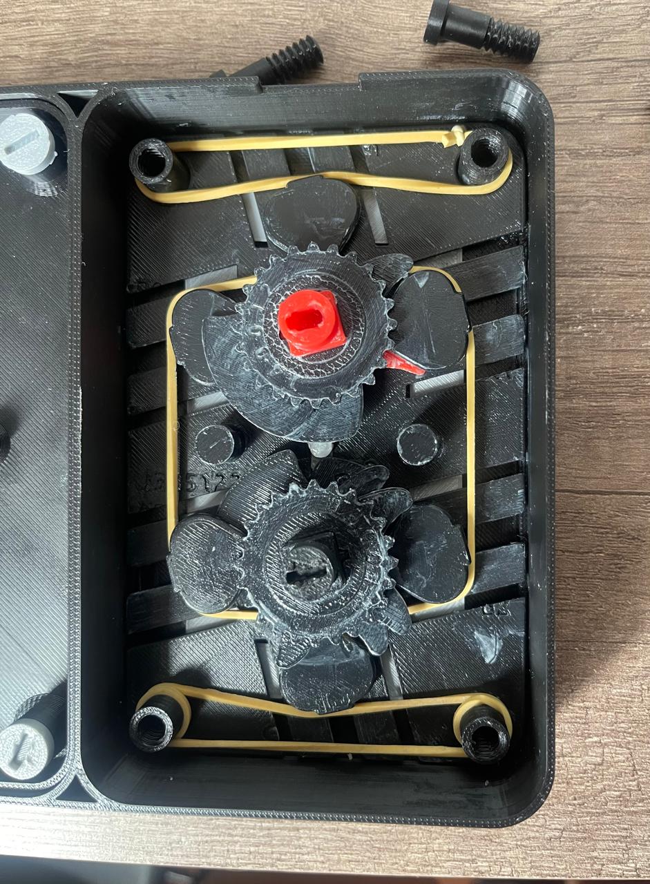
In the video, you can see that I used glue because, as the gears are placed separately, when turning, the numbers tend to separate, causing the numbers to not be visible. Another important point is that the sanding process is essential because if there are any irregularities between the pieces, they do not move smoothly, making it more difficult for the motor to move everything.
Important note: I recommend using some type of lubricant for the gears and the segment flowers, as reducing the resistance on the gears will make it easier for the motor to move the necessary steps to advance to the next number. Each number corresponds to a 20° rotation.
If you need some help with 3D printing, you can refer to my Week 5, which covers 3D Scanning and Printing.
PCB
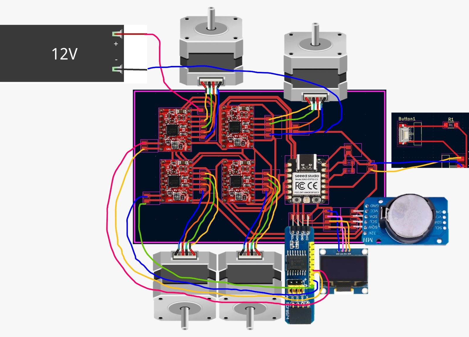
For the PCB design, I arranged it to accommodate the Xiao ESP32C3, four A4988 stepper motor driver modules, PCF8574 I2C GPIO Expander Module, OLED screen, RTC DS3231 module, and a button. I used KiCad to design my PCB and the ROLAND SRM-20 machine to create the PCB on a 10 cm x 15 cm phenolic board.
Below is the way they are connected:
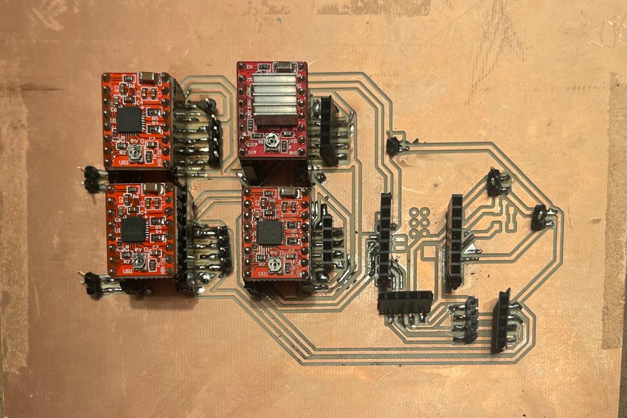
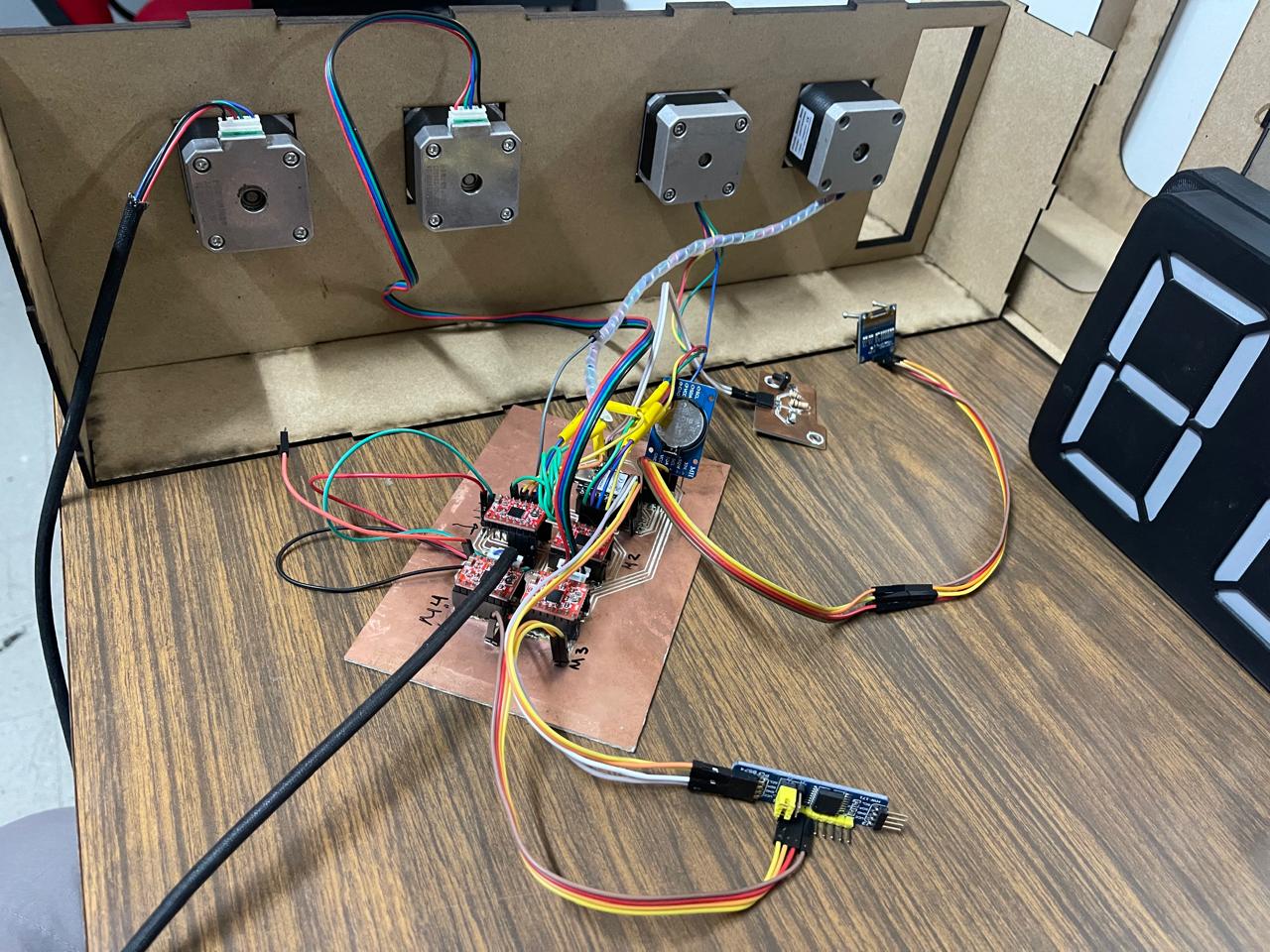
If you need more help on how to use the ROLAND SRM-20 to make the PCB, you can refer to my Week 4. Alternatively, if you want to redesign the PCB and need assistance with KiCad, you can check out my Week 8.
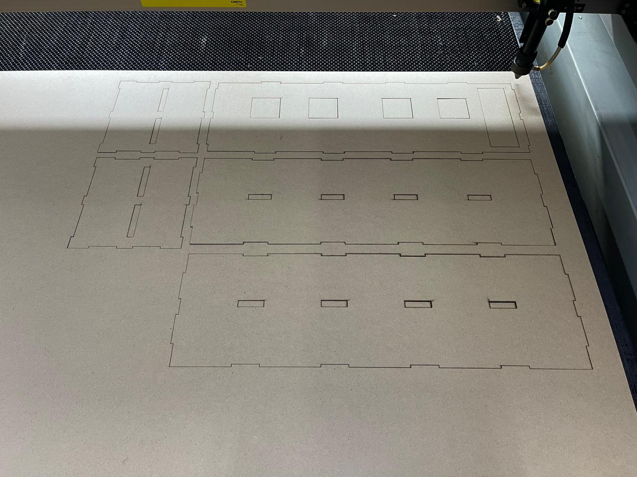
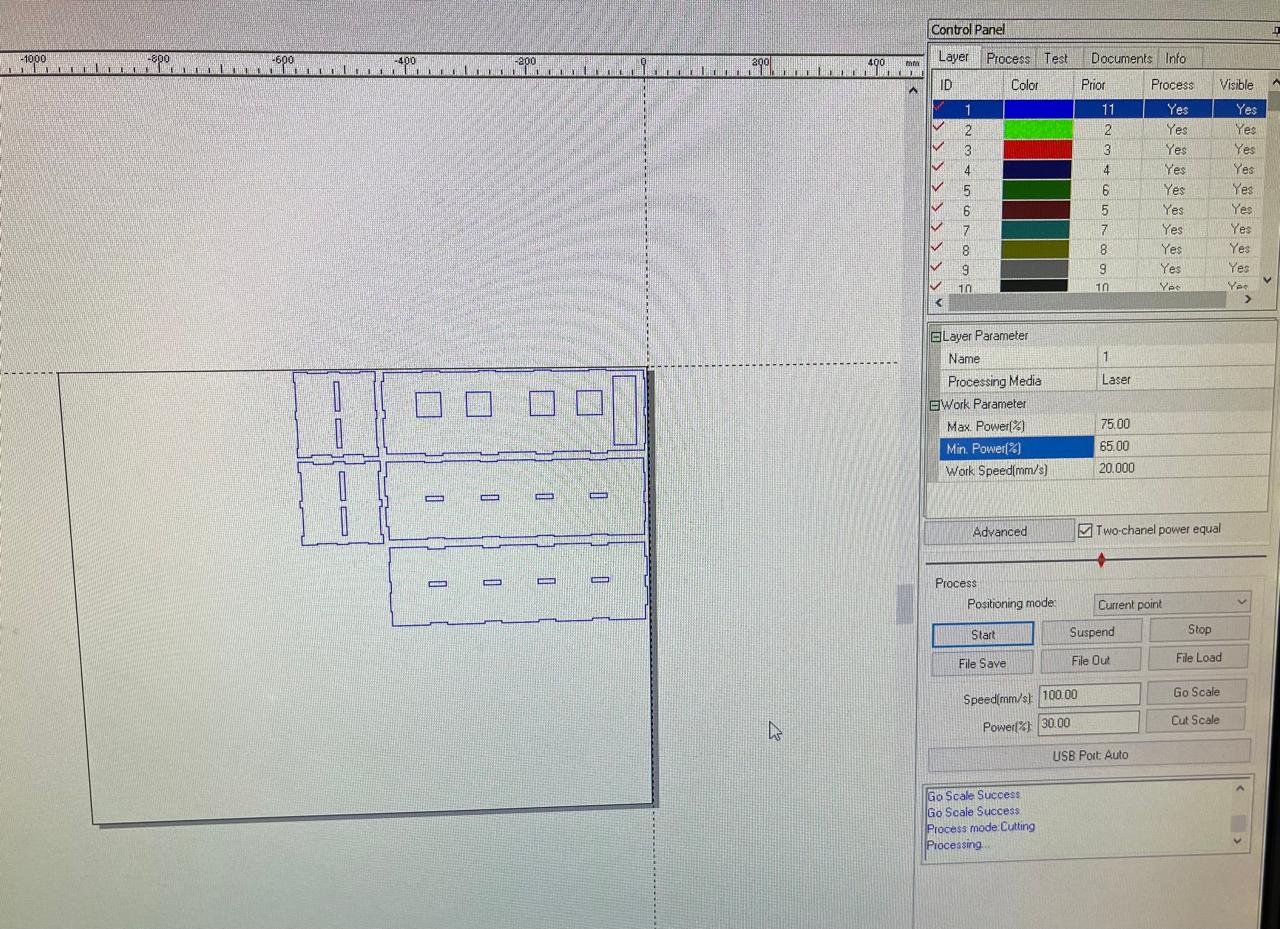
Laser Cutting
For this part of the project, I used the FAB LAB Puebla Laser Cutters CFL-CMA1200. Below, you will find the quantity of pieces you need to cut from each of the documents:
- (1) Atrás
- (1) Frente
- (2) Lateral
- (3) Medio
- (2) Tapas
Download the zip here. Carcasa.zip
Remember to place the motors in the middle piece. If you have any questions about how to assemble it, I have included the Assembly here. Ensamblaje_Carcasa.SLDASM
If you need more help with laser cutting, you can go to my Week 3 for support.
Programming
For the programming part, since we are using the RTC DS3231 module, the first thing we need to do is insert a 3V battery into the module. After connecting everything, we upload the Reajuste_HORA.ino program. This step is crucial to set the current time in the module's memory. With this setup, even if the PCB is disconnected from the computer or its power source, the module won't forget the time as it has its own battery. The code was modified from ChepeCarlos.
Afterwards, if you want to test that all your motors and the screen are working 100%, you can upload the following code: Pantalla_RTC_Motores_Pruebas.ino.
With the following program, you can start counting along with the Pomodoro method by pressing the button.
Contador.inoFor the weather part using an API, the first step is to choose the data source. In this case, I used the OpenWeather API. The first code you should test is WiFi.ino. Enter your internet network name and password to verify that it works.
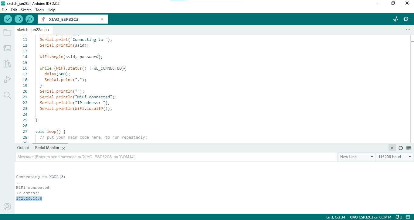
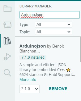
Once it has worked, you can now try loading the Weather.ino code, where you will be able to see the temperature of the requested location and the weather description in the serial communication. For this part, it's important that you download the ArduinoJson library.

If yo want to see the API on acction yo can do whit this program: Api_pantalla.ino