4. Electronics Production
This week I worked on made and test a microcontroller development board.
Research
PCB
Printed Circuit Boards (PCBs) are essential in modern electronics, providing a physical platform for connecting electronic components and facilitating the flow of current between them. These boards are made of an insulating substrate, typically fiberglass coated with a thin layer of copper, onto which circuits are etched using chemical etching or milling methods.
Ironing method and contamination
The ironing method, while common, involves transferring a design printed on special paper onto a copper board using heat and pressure. However, this process can generate chemical and thermal waste, which can be harmful to the environment and human health.
CNC milling for PCBs
CNC (Computer Numerical Control) milling offers a cleaner and more precise alternative for PCB manufacturing. With this technique, a high-precision milling head is guided by a computer program to cut away excess copper from the board, thereby creating printed circuits with exceptional accuracy and detail.
FAB LAB Puebla Electronics Production
The Universidad Ibero Puebla has a high-quality CNC milling machine, the ROLAND SRM-20, which enables students in FabLab to fabricate their own PCBs efficiently and accurately. This equipment provides an opportunity for learning and working with cutting-edge technology, fostering the development of practical skills and innovation in the field of electronics.
You can see the group assignment here. FAB LAB Puebla Electronics Production. I think one of the key points to highlight about this group task is that we need to consider how wide we configure our tracks. If we don't take into account the thickness of our tool, it can eat up a good portion of the track. Considering that it's important to have wider tracks for higher amperage and to avoid short circuits, this is something that must be taken into consideration.
How I made the toolpad
- Download the two .zip files (VPanel-for-SRM-20_Installer and WIN10X64).
- Download the two .png files (CutPuebla and tracespuebla).
- Open the MODS link.
- Right-click.
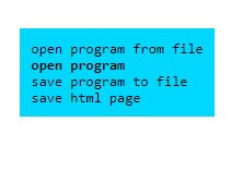
- Select Programs.
- Select Open program.
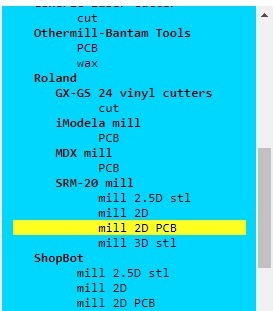
- Roland -> SRM-20 mill -> Mill 2D PCB.
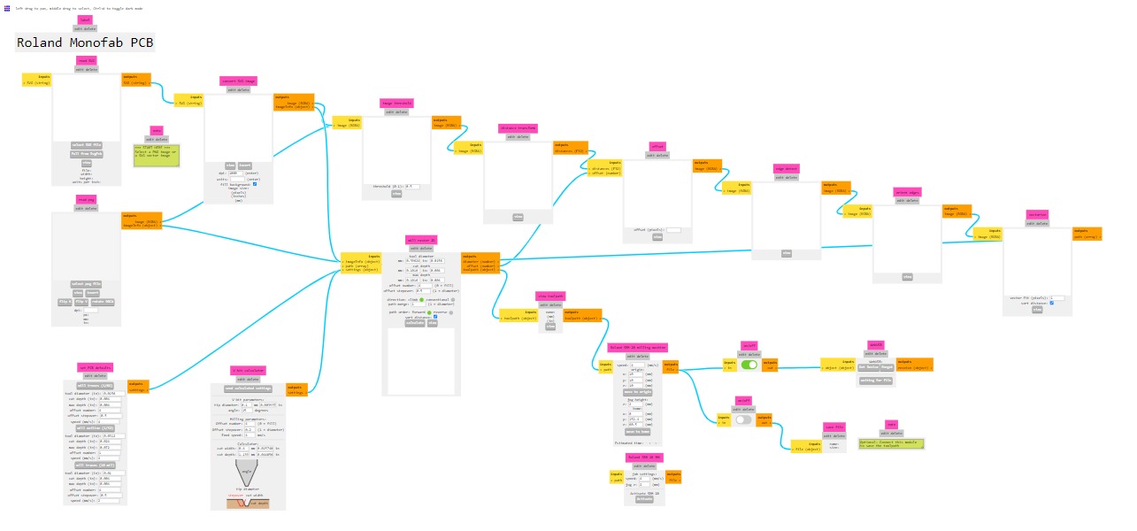
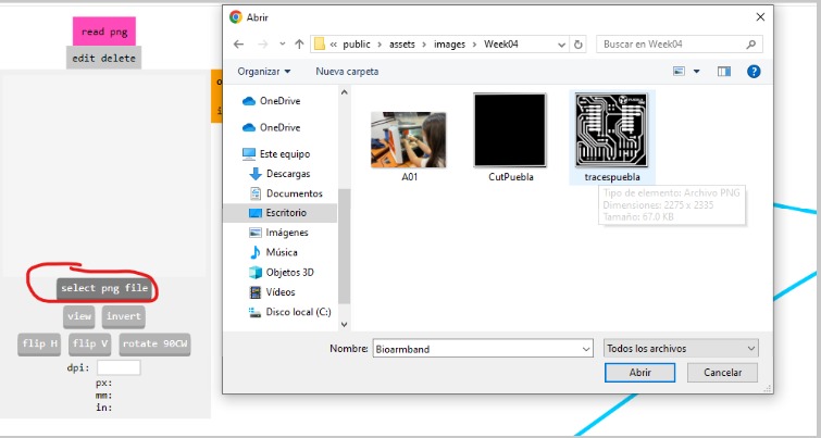
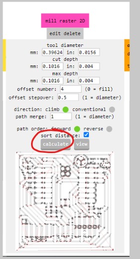
- In the Read png tab, select png file. In this case, I chose tracespuebla to generate the traces on the copper board.
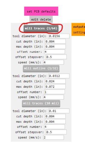
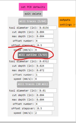
- In the set PCB defaults tab, select mil traces (1/64).
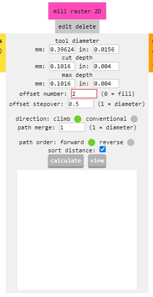
- In the mil raster 2D tab, configure the offset number to 2.
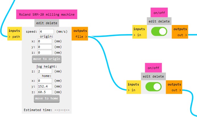
- In the Roland SRM-20 milling machine tab, set the origin x, y, z to 0. The sliders on the right should both be turned on.
- In the mil raster 2D tab, press calculate, and it will open a tab with the path the machine will use and will be downloaded.
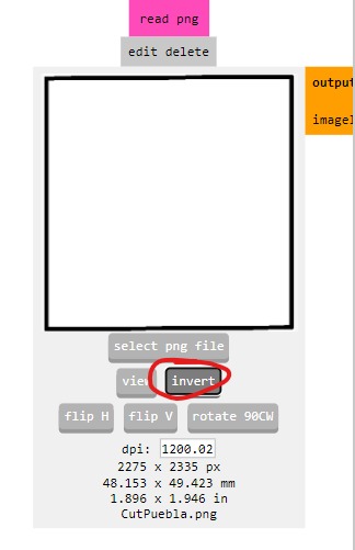
- Repeat step 9 and now choose the Cutpuebla file.
- Select invert to avoid the process being done incorrectly and eating the trace from the tracespuebla file.
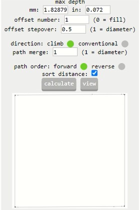
- In the set PCB defaults tab, select mil outline (1/32).
- Repeat steps 12 to 15.

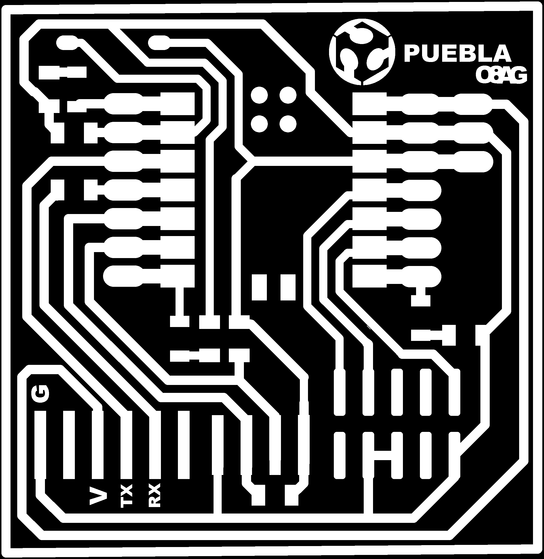
How I made the board
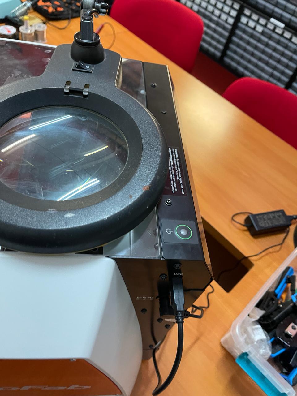
- We turn on the ROLAND SRM-20 machine.
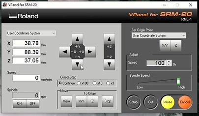
- We open the VPanel for SRM-20 application when the machine is connected and ready to be calibrated.
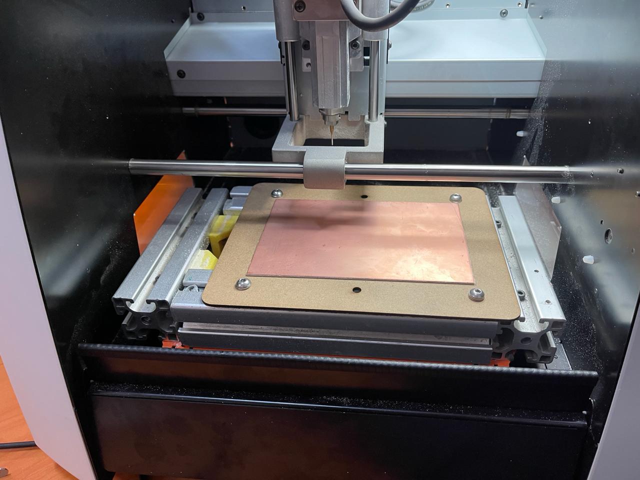
- On the machine, we must place the copper board taped with double-sided tape to the sacrificial bed made of MDF.
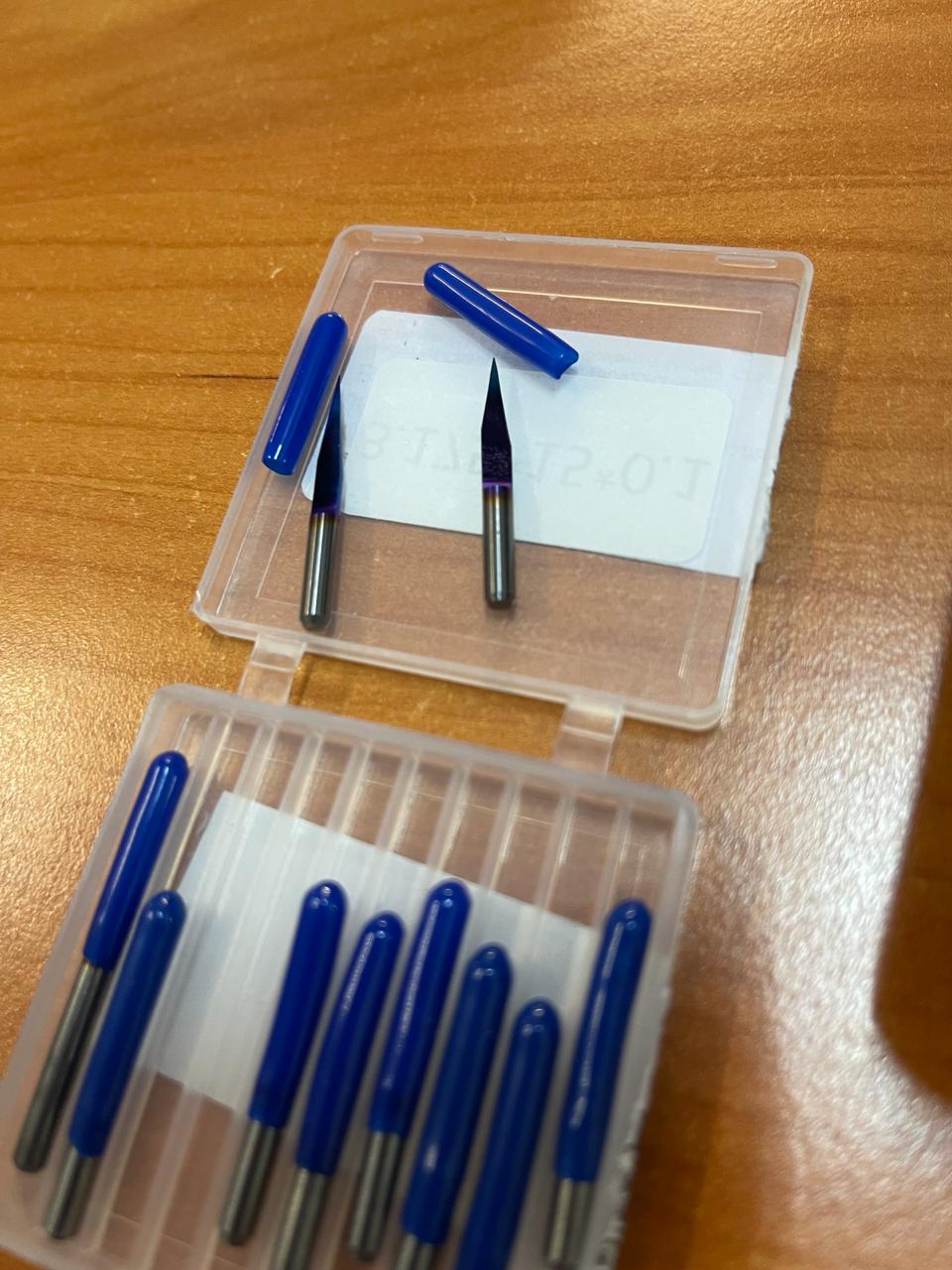
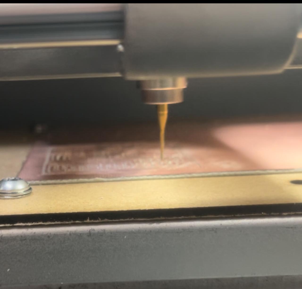
- We use the sharpest tool to make the superficial cut of the copper traces, as cutting the outline first may cause it to move and the PCB may not come out correctly.
- Using the program's x,y arrows, we can move the copper board so that the tool is positioned at one of the corners.
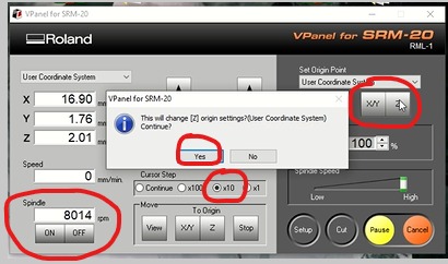
- We adjust the z-axis very carefully to avoid crashing the tool into the board. First, we move it with the Continue setting. When it gets close, we switch to x100 setting and, placing a piece of paper on the board, we start lowering it with x10 setting until we feel it scratching slightly.
- We press the ON button under Spindle, ensuring it reaches a speed of over 7700 rpm, then we lower the z-axis by two clicks (or until it starts to cut the material) using the x1 setting.
- We save the Z-axis configuration by pressing its button located in the upper right side. A dialog box will appear asking if we want to set that point as our origin, to which we'll answer yes.
- We do the same for the X/Y axes.
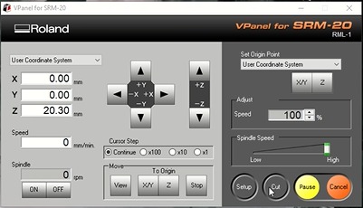
- We raise the z-axis using the Continue setting.
- We press OFF under Spindle.
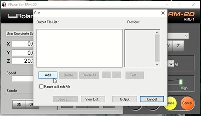
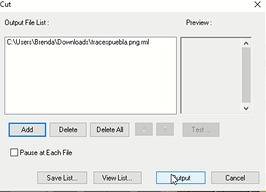
- We load the program by selecting the circular CUT button.
- Using the ADD button, we locate the tracepuebla.png.rml file.
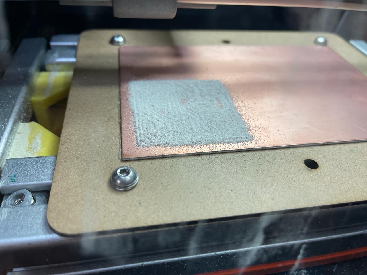
- We press the Output button to start cutting.
- Once the traces are cut, we can proceed to cut the outline. For this, we need to change the tool to a thinner drill bit.
- We recalibrate the z-axis with the changed tool and paper, but this time without Spindle and without lowering it further (just until it scratches the paper). DO NOT MOVE THE X/Y AXES.
- We locate the file and press CUT.

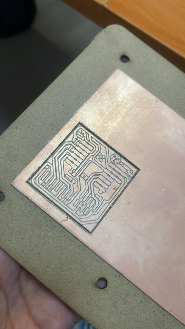
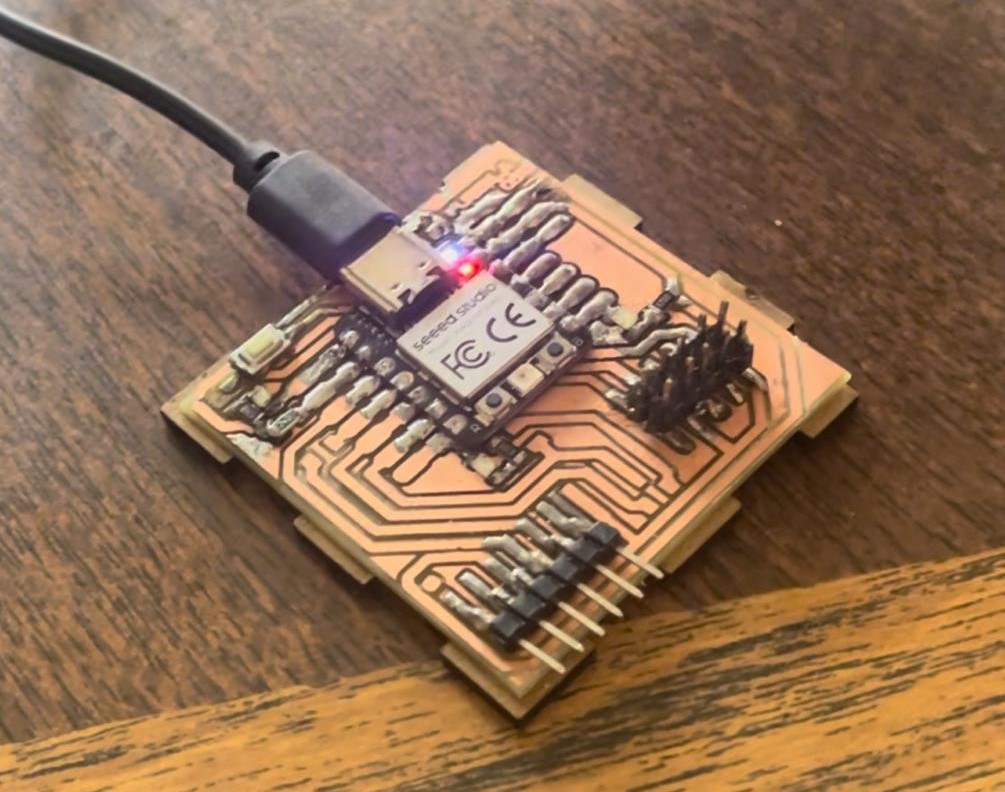
For the soldering part, I encountered some small issues because the insulating tape I placed behind the microcontroller shrunk, causing some parts to come into contact with the PCB tracks. My solution was to place the microcontroller with slightly taller pins.
- Xiao RP2040
- 1 kOhm and 2 kOhm resistors
- LEDs
- pins
- button
The components that I used and soldered were:
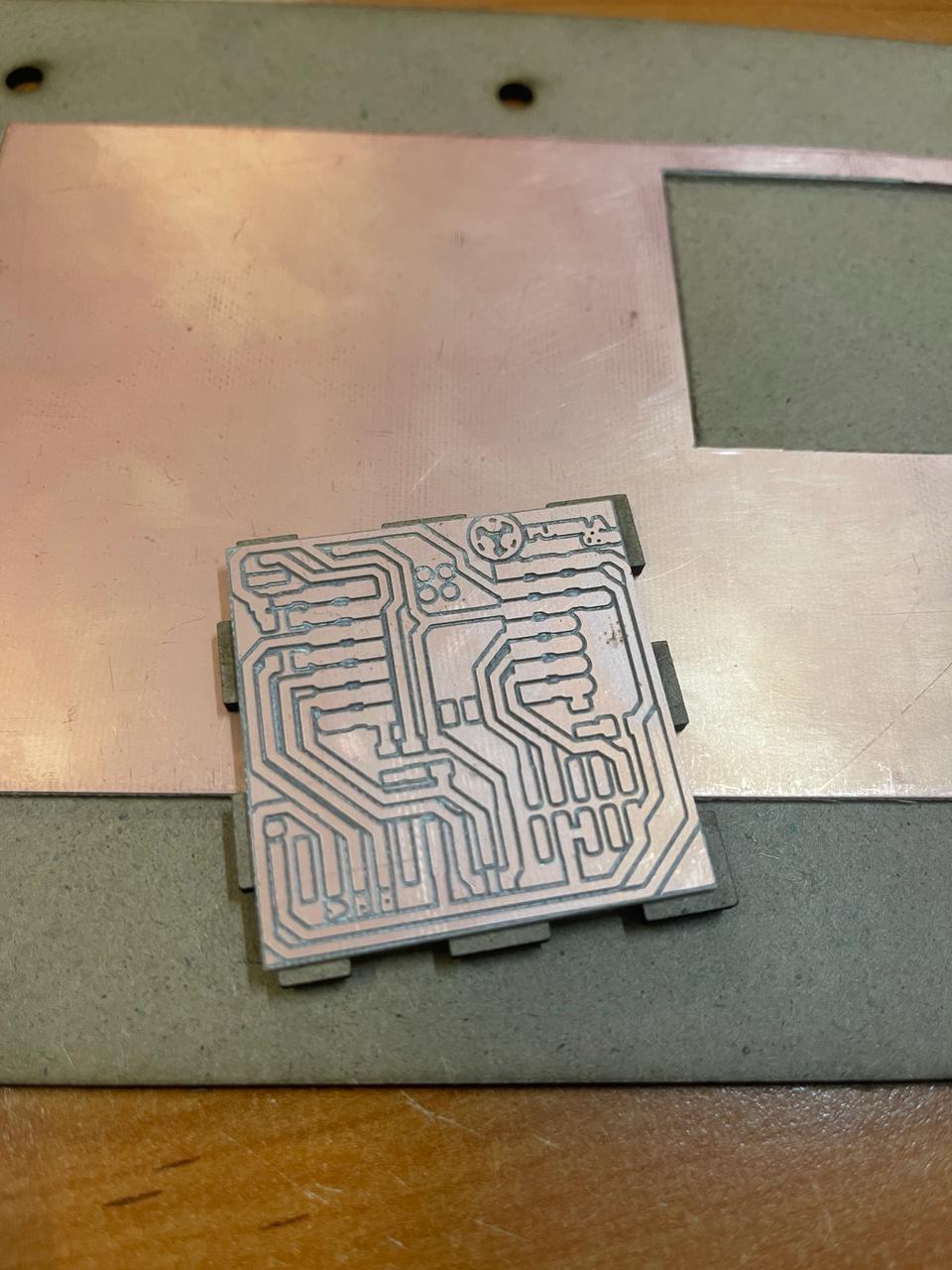
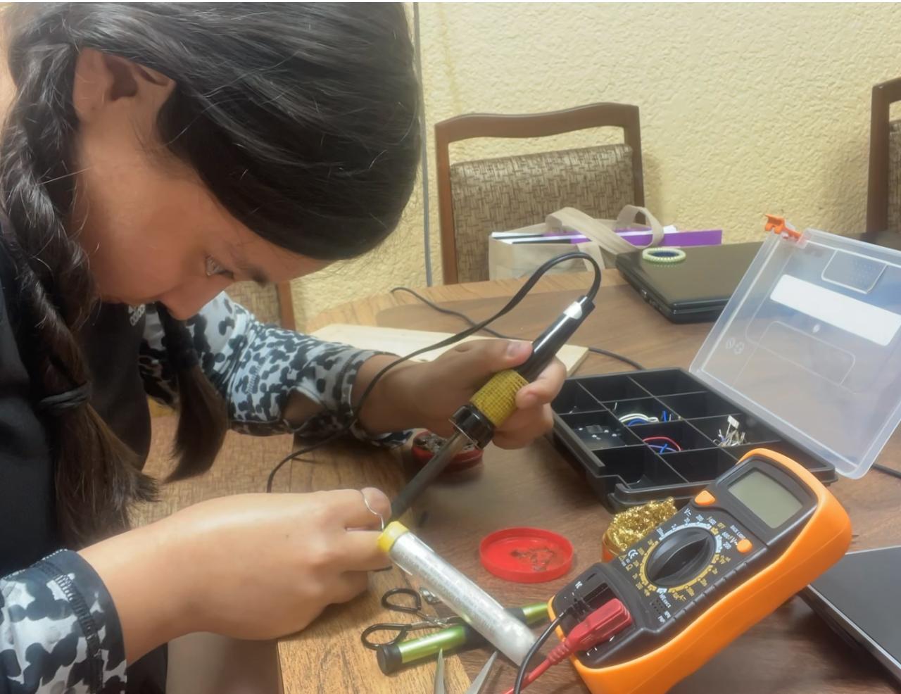
Once I obtained the board, I removed it to solder it with the components, then I loaded the program that is located in the download list at the bottom of the page.
Programming in Arduino
Arduino is an integrated development environment (IDE) and an open-source hardware platform used for prototyping electronic projects. As programming software, Arduino provides users with a friendly environment to write, compile, and upload code to Arduino microcontroller boards. With a wide range of libraries and a simple syntax based on C/C++, its popularity stems from its accessibility, versatility, and active community of users who share knowledge and projects.
For this part of Arduino programming, I selected the following steps:
First, you must download the following link "//github.com/earlephilhower/arduino-pico/releases/download/global/package_rp2040_index.json" by copying and pasting it into the File -> Preferences section.
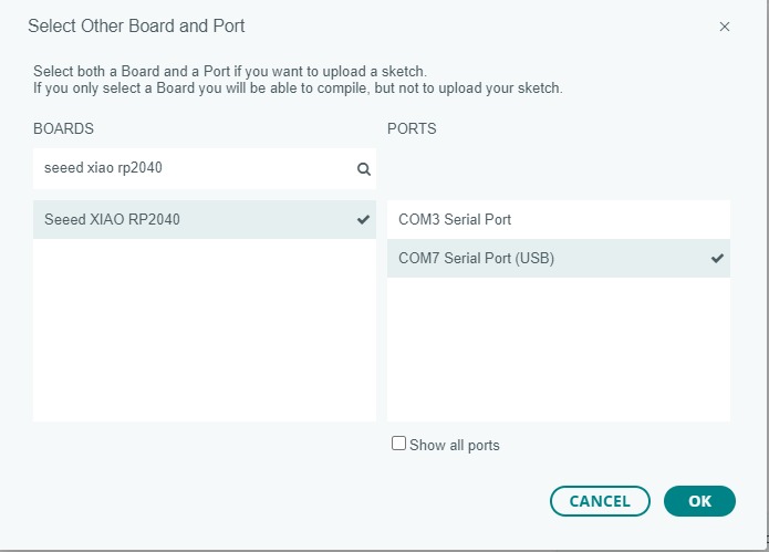
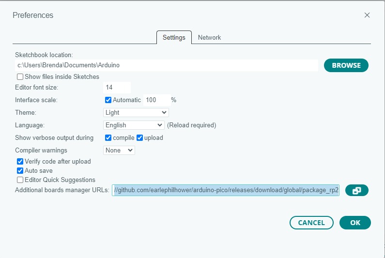
Then, in the Select Board section, I pressed "Select other board and port".
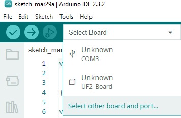
I search for the "Seeed XIAO RP2040" microcontroller and make sure to carefully select the correct port to avoid struggling with uploading the program.

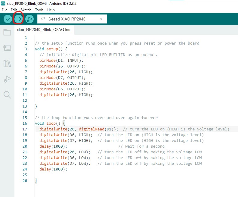
Now, all that's left is to upload the program with the following button, and that's it.
Problems and how I fixed them
- Please note that if the material is not being cut, the z-axis should be recalibrated.
- Close the machine door to begin cutting; otherwise, the machine will issue a warning and won't allow any action.
- When pressing OUTPUT to start cutting, ensure that the x, y, z points have been saved in the calibration. Though it didn't happen to me, I suppose it could have caused a mis-cut.
- When I started soldering, some solder dripped, causing continuity between ground and voltage when checked. Consequently, I had to remove several components again to clear away the spilled solder.
Conclusion
For this week, the most important thing was learning how to use the machine so that I can later learn to make my own PCBs. For now, the most important thing was understanding how to place the tools and the correct way to position the copper board on the bed, as well as configuring the G-code.
