Week 10

Mechanical Design and Machine Design

  • Design a machine that includes mechanism + actuation + automation + application.
  • Actuate and automate your machine


Our team:

...
Augusto Mantilla
Mechatronic Engineering student
...
Brenda Pastrana
Biomedical Engineering student
...
Gabriela Tamanis
Industrial Design student
...
Luis Bulas
Mechatronic Engineering student
...
Olaf Garcia
Mechatronic Engineer
...
Jose Manuel Alvarez
IDIT
...
Erick Guevara
Computer Systems Engineering student
...
Ximena Cisneros
Biomedical Engineering student
Hola

- The idea -

A CNC (Computer Numerical Control) machine is a manufacturing tool that operates under the control of a computer program. It utilizes numerical data input to automatically execute precise and complex machining operations. CNC machines are capable of cutting, drilling, milling, turning, and other processes with high accuracy and repeatability

The idea is to create a CNC sewing machine, where there is a movable bed controlled by a computer to embroider any image converted into code. The CNC sewing machine would essentially operate similarly to other CNC (Computer Numerical Control) machines, but instead of cutting or engraving materials, it would use a needle and thread to sew designs onto fabric. The computer would interpret digital images or designs and convert them into instructions (G-code) that the machine can understand, allowing it to precisely sew intricate patterns or designs onto fabric with high accuracy and consistency. This technology would offer a more automated and customizable approach to embroidery, enabling users to create detailed and complex designs with ease.

- Materials -

Quantity Material
3 Motors 17hs4401
4 Belts
8 Bearings
4 Guides of 6mm of diameter
2 Guides of 4mm of diameter
1 Sewing machine brother MODEL LS-2125i
1 Arduino UNO
1 Shield CNC arduino UNO
1 Power supply of 12 V

- Design and Assembly -

In our pursuit of an optimal machine design, our foremost consideration was simplicity. We aimed to create a structure that is not only straightforward but also lightweight, ensuring ease of handling and maneuverability. It was crucial for us to strike a balance, avoiding excessive weight that could impede its functionality while still maintaining structural integrity. Additionally, we were mindful to steer clear of any unnecessary bulkiness or unwieldiness, ensuring that the machine's footprint remains compact and its presence unobtrusive within its intended workspace.

    Bed

  1. Initially, it was imperative to undertake meticulous measurements to ensure the development of a suitable design for the machine. This crucial phase involved our team meticulously assessing dimensions and spatial requirements to guarantee precision in every aspect of the machine's construction. Here are some captivating snapshots showcasing our dedicated team diligently engaged in this pivotal process. First it was designeg the bed. You can check a better procedure of the bed in Gaby's fabacademy page. Here is a very resume process of it:

  2. Hola
  3. In our meticulous design process, we took careful consideration of precise measurements, particularly accounting for the kerf, whether for 3D printing or laser cutting.

  4. Hola
  5. Selecting the appropriate plane to work with is a crucial decision in any design process, influencing the overall efficiency and precision of the project. By carefully considering factors such as the orientation of features, ease of access, and alignment with functional requirements, we ensure optimal results:

  6. Hola
  7. Remember: MAKE EVERYTHING PARAMETRIC !!

  8. Hola
  9. In the process of fabricating the component where the screw will be embedded, meticulous attention to detail was paramount. Precision was our guiding principle as we crafted this integral part of the assembly.

  10. Hola
  11. Utilizing the tools mastered in Fusion 360 for solid modeling and creating perforations, we embarked on a comprehensive design approach. Leveraging features such as extrusions, revolves, and lofts, we meticulously crafted solid bodies representing each component of the design.

  12. Hola
  13. This part its goint to be joint to the part of the motor, so it can freely move.

  14. Hola
  15. Here is an assembly of how it should look like:

  16. Hola
  17. Here we measure it on the machine, in order to check it actually fits properly.

  18. Hola
  19. First, we tried to move it and sew something, just to verify that our idea might work as we wanted.
BED Fusion document
F3D document

    Structure of the CNC

    Then the Structure of the CNC was designed. You can check a better procedure of this in Xime's and Brenda's fabacademy page. Here are just the pieces and the assembly on SolidWorks:

    Part: SLDPRT document DXF document
    Hola Solidworks document of this part. DXF document of this part.
    Hola Solidworks document of this part. DXF document of this part.
    Hola Solidworks document of this part. DXF document of this part.
    Hola Solidworks document of this part. DXF document of this part.
    Hola Solidworks document of this part. DXF document of this part.
    Hola Solidworks document of this part. DXF document of this part.

    Assembly as it is supposed to look like:


    Hola

    -CNC cut-

    1. Initially, we opted for CNC cutting, utilizing a 15mm MDF table as our substrate. This choice was made with deliberation, considering factors such as material stability, precision, and suitability for the intended application.

    2. Hola
    3. Here's an enhanced photograph showcasing the assembly process of the structure. This snapshot captures the meticulous arrangement of components, highlighting the precision and care invested in each step of construction.

    4. Hola

      Hola

      Hola
    5. You see us happy, but it was the third time we had to cut it because it was not fully rigid.

    6. Hola
    7. Final assembly

    8. Hola

    -Conection-


    Hola

    Hola

    - Installation of the UGS-

    UGS, or Universal Gcode Sender, is a popular software interface used for sending G-code commands to CNC machines, such as those controlled by GRBL. It's an open-source application that enables users to communicate with their CNC machines, sending instructions for cutting, engraving, drilling, or performing other operations. UGS is compatible with multiple platforms and stands out for its user-friendly interface, allowing users to load G-code files, visualize toolpaths, and adjust machine settings in real-time.

    You can check a better procedure of this in Erick's, Luis's, Augusto's , Olaf's and Manuel's fabacademy page.

    Here are the steps:

    1. We visited their website through our browser: https://winder.github.io/ugs_website/

    2. Hola
    3. To download the latest version of the software, we click on "Download". In this new tab, we select our operating system. In our case, we use Windows and download version 2.1.6.

    4. Hola
    5. Once the download is complete, it will provide us with a compressed file, so we need to unzip it. We use WinRAR to unzip the folder.

    6. Hola
    7. We open the folder and navigate to "bin". Inside the bin folder, we will find the program named "ugsplatform64". Before opening it, we create a shortcut on the desktop to save us this step every time we use it.

    8. Hola
    9. It takes a bit of time to load, but we can now use this interface.

    10. Hola

    - Installation of GRBL on Arduino Uno for CNC Control-

    Prerequisites:

    • Arduino Uno
    • USB cable to connect the Arduino to the computer
    • Arduino IDE (latest version)
    • GRBL firmware (latest version available on GitHub GRBL)

    - Instalation-

    Step 1: Software Preparation

    1. Download and install the Arduino IDE from www.arduino.cc.

    2. Hola
    3. Download the latest version of GRBL from GitHub GRBL Releases.

    4. Hola

      Hola

      Hola
    5. Unzip the GRBL ZIP file.

    6. Hola

    Step 2: Uploading GRBL to Arduino

    1. Open Arduino IDE and go to "File" > "Open", navigate to the unzipped GRBL folder, and open grblUpload.ino.

    2. Hola
    3. Upon opening the file, we will see the following.

    4. Hola
    5. Connect the Arduino Uno to the computer using the USB cable.
    6. In Arduino IDE, select "Tools" > "Board" > "Arduino Uno".
    7. Select "Tools" > "Port" and choose the port to which the Arduino Uno is connected.
    8. Press the "Upload" button to upload GRBL to the Arduino Uno.

    - Universal Gcode Sender (UGS) Interface

    Within UGS, we have many tools for operating CNC machines.


    Hola
    • Top Toolbar: This bar contains icons for quick operations such as opening G-code files, setting up the connection to the machine, and accessing various UGS tools and settings. Here, you select the firmware (usually GRBL), choose the correct port to which the Arduino is connected, and adjust the baud rate for communication.

    • Hola
    • Status Panel: Displays vital information about the connection status between UGS and the CNC. It indicates whether the machine is connected and ready to receive commands or if there are any connection issues.

    • Hola
    • Manual Motion Controls: A set of buttons that allow manual control of the CNC machine axes. You can move the X, Y, and Z axes in defined increments, which is useful for initial positioning or verifying movement.
    • Steps and Speed Configuration: In this area, you can define the amount of movement per command sent and adjust the machine's feed rate. This is crucial for precise work and for adapting the machine to specific operation needs.

    • Hola
    • Control Panel: Provides shortcuts to frequently used functions such as "Reset Zero" to establish the work origin and "Return to Zero" to return to the defined origin point. It also allows unlocking the controller and checking the current machine status.

    • Hola
    • Console: A text window that shows real-time communication between UGS and the CNC machine. Here, sent commands, machine responses, and any error messages are displayed. It is useful for diagnosing problems and confirming that G-code commands are being sent correctly.

    • Hola
    Sketch to comunicate the Arduino with the UGS
    grblUpload.ino

    - Test -


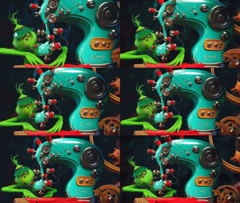
    Grinch cociendo

    The first test, but everything moves.


    Hola

    Erick and Agusto working on the movement of the motors.


    Hola

    - Final Result Video -


    Here are some of the final results we made, an "F" of Fabacademy and a rectangle.


    Hola
    Square document
    g-code
    "F" document
    g-code

    - Mistakes and how we solved them -

    Problem How we solve it
    The heightened sensitivity of the machine is primarily attributed to its construction material, which is 3mm MDF. Furthermore, "L" brackets were installed strategically to provide additional support and stability to the structure. As it was of 3 mm it was really sensible, we even thought that with the movement of the motors, the structure might fail and break.
    Hola
    To address this issue, we decided to re-cut the machine parts using a thicker MDF, specifically 15mm thick, instead of the previous 3mm thickness. This change in material thickness provides a sturdier and more robust foundation for the machine components, enhancing their durability and stability.Additionally, we took extra care during the assembly process to ensure that the tabs and slots, which are used for connecting the various parts together.
    Hola
    We encountered a setback during the assembly process when we inadvertently broke a crucial piece that was intended to support a motor located at the top of the machine. There were three primary failures contributing to this issue:
    1. Firstly, the tubes we intended to use did not fit properly into their designated slots or connectors.
    2. Secondly, we overlooked the inclusion of tabs or brackets necessary for securing the motor's belt in place.
    3. Lastly, there was a discrepancy in the dimensions of the tubes, as they were slightly larger than anticipated by approximately 1mm.
    Lastly, there was a discrepancy in the dimensions of the tubes, as they were slightly larger than anticipated by approximately 1mm. This minute difference rendered the tubes incompatible with the designated spaces, resulting in further complications during assembly.
    Hola
    Despite the structure being constructed from heavy 15mm materials, the persistent vibration generated by the sewing machine caused significant movement throughout the entirety of the framework. This unexpected issue highlights the importance of considering not only the weight and thickness of materials but also the potential for external factors such as machine vibration to affect the stability and performance of the structure. Additional measures may be necessary to mitigate this movement, such as incorporating vibration-absorbing materials or reinforcing specific connection points to enhance overall stability. Only a limited quantity of anti-slip patches were acquired for application on both the machinery and the framework, strategically aimed at bolstering their ability to withstand vibrations.
    Hola

    Hola

    Possible chagnes:

    The proposed improvements aim to enhance the functionality and durability of the pedal.

    1. Enclosing the pedal in a sturdy casing will shield it from external damage and prolong its lifespan.
    2. Reinforcing the structure slightly to add some weight while maintaining portability through a detachable design will ensure stability during use and ease of transport.
    3. Integrating a protective frame around the power source will safeguard it from potential harm, reducing the risk of malfunctions due to exposure.
    4. Eliminating the need for patches to prevent vibrations and movement will streamline the setup process, enhancing user experience and efficiency.