Mechanical Design, Machine Design
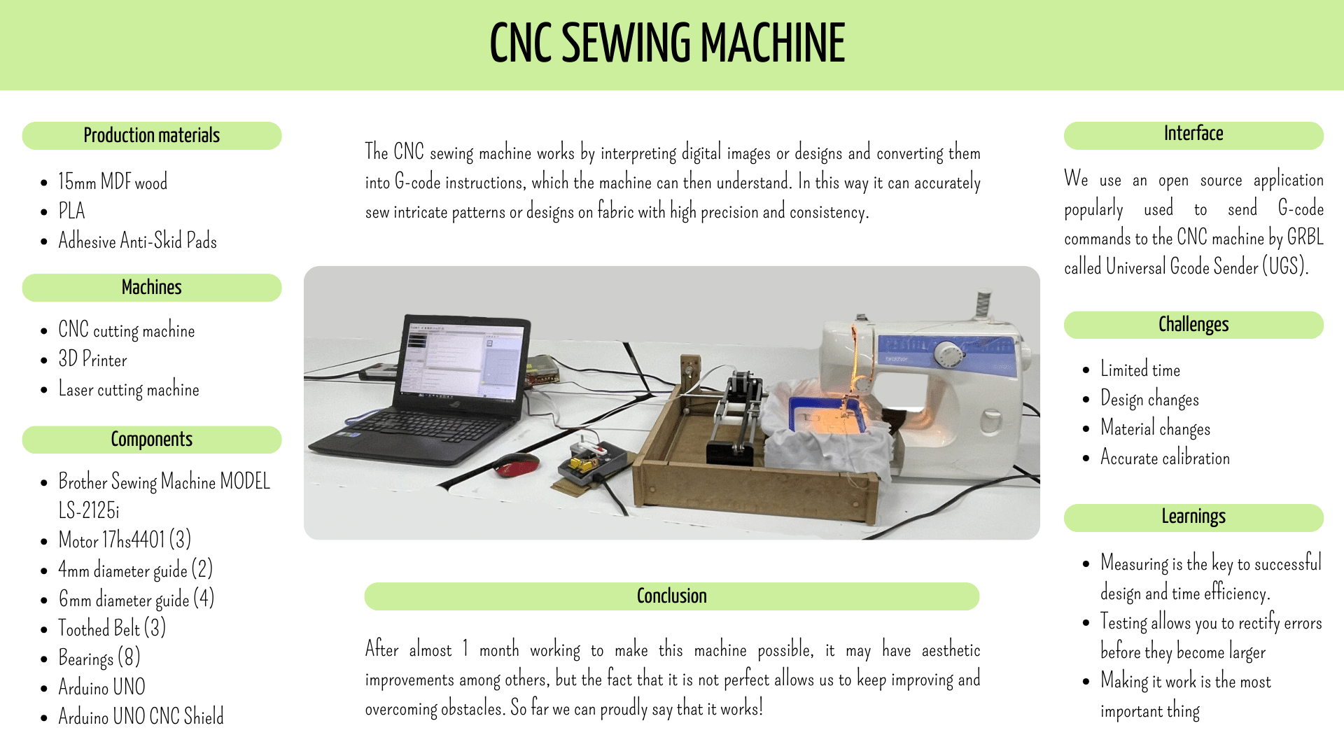
Here its our group assigment: Week 10We developed a CNC sewing machine capable of embroidering designs sent to its interface with a given G-code. This machine allows users to input any desired design or pattern through the interface, which is then translated into instructions using G-code. These instructions are then executed by the CNC sewing machine, resulting in precise and accurate embroidery according to the provided design.
Our team:
Our team was composed as you can see in the image, Gaby, me, Brenda, Augusto, Emannuel, Luis, Erick and Olaf.
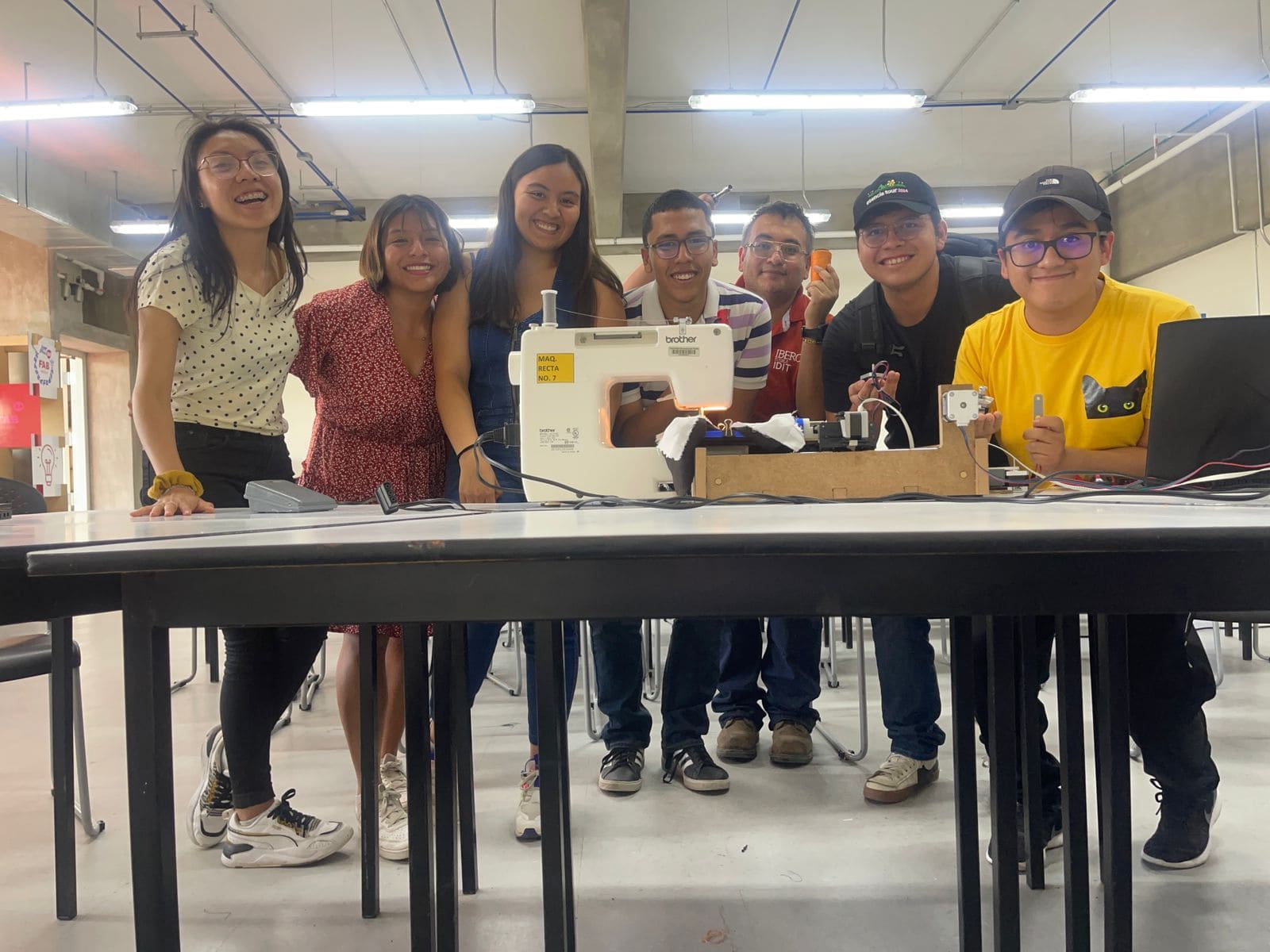
We divided the tasks so that Gaby, Brenda, and I were focused on the design aspect, ensuring that the machine could operate effectively. Augusto, Emanuel, Luis, Erick, and Olaf, on the other hand, concentrated primarily on the interface, programming, and connectivity of the machine and the sewing apparatus.
Individual assigment
- Document your individual contribution
- To create the machine design, I utilized SolidWorks because it's the software I'm most familiar with.
- SolidWorks is a computer-aided design (CAD) software program that allows users to create 3D models, simulations, and technical drawings. It's widely used in various industries for product design, engineering, and manufacturing purposes.

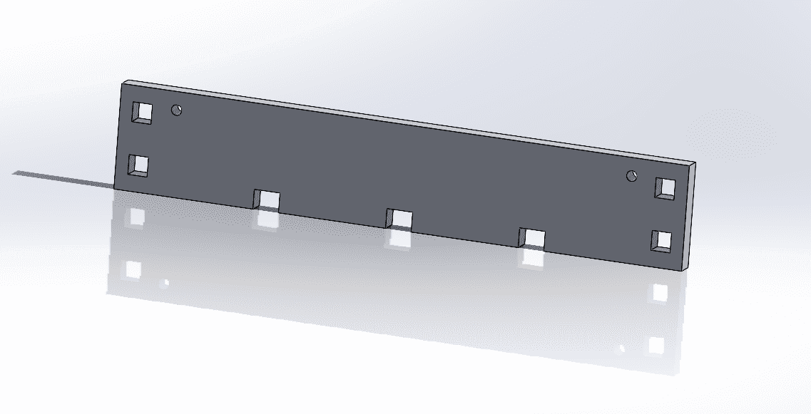
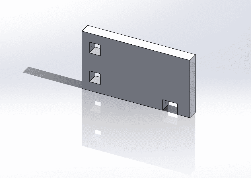
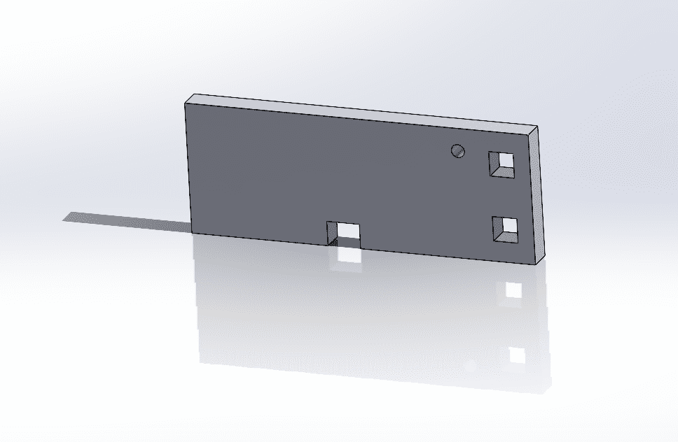
Here are the steps for doing the structure of the CNC:
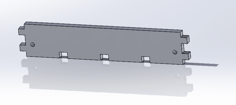
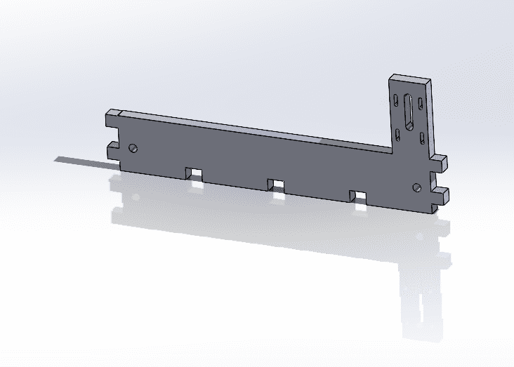
- Take measures of each part, so everything properly fits.
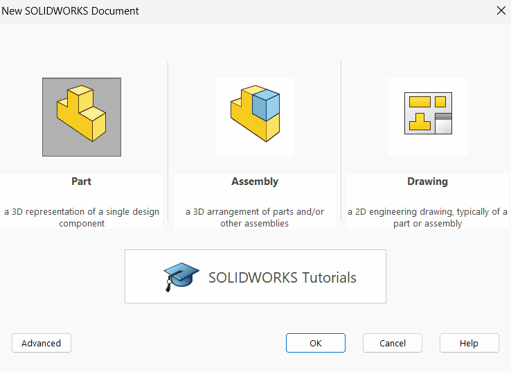
- Launch the SolidWorks software on your computer.
- Begin by creating a new part file where you'll design your component.
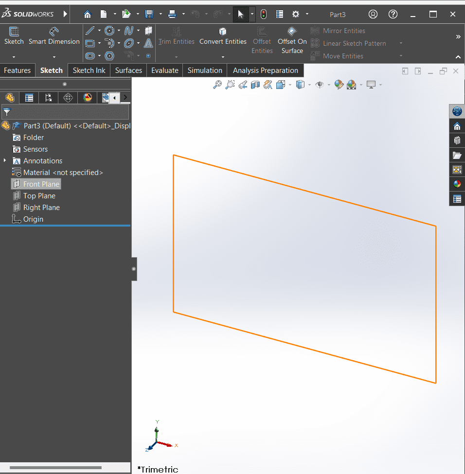
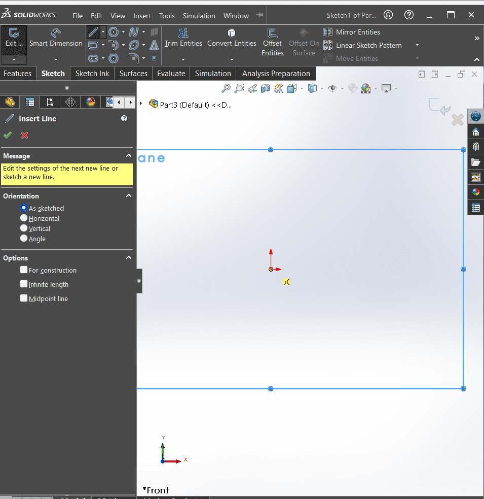
- Once the part file is open, enter sketch mode. This can typically be done by clicking on the "Sketch" tab in the toolbar and selecting "Sketch" from the dropdown menu.
- Select the plane where you want to sketch your lines. This can be the front, top, or right plane depending on your design requirements.
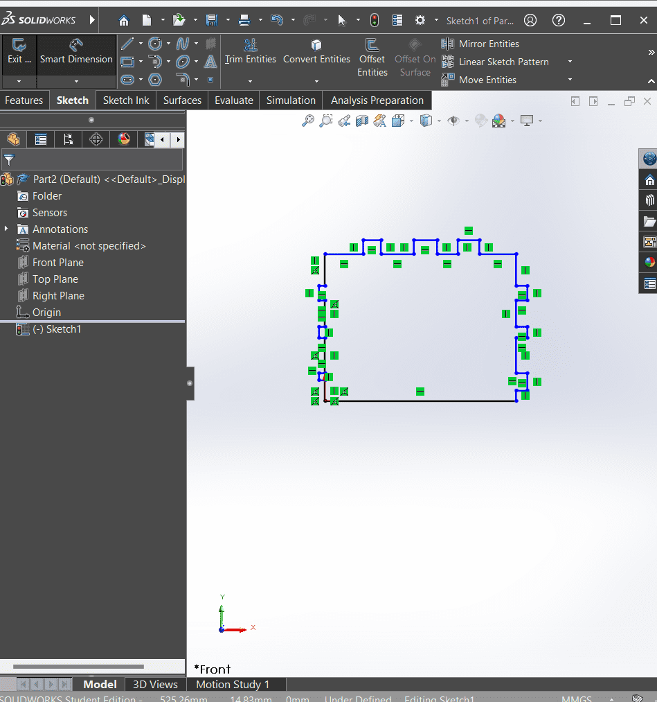
- Use the drawing tools within SolidWorks to sketch the lines for your part. This may involve using the line tool, rectangle tool, or other sketching tools as needed to create the desired shape.
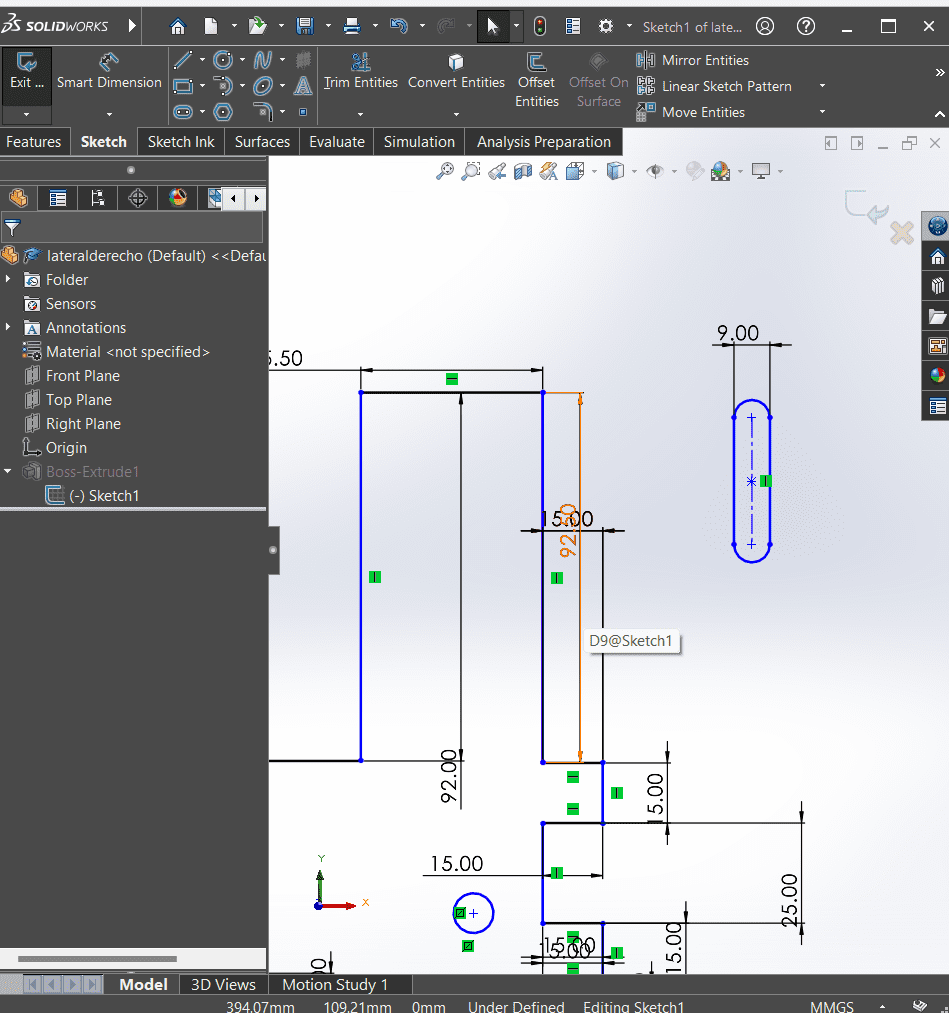
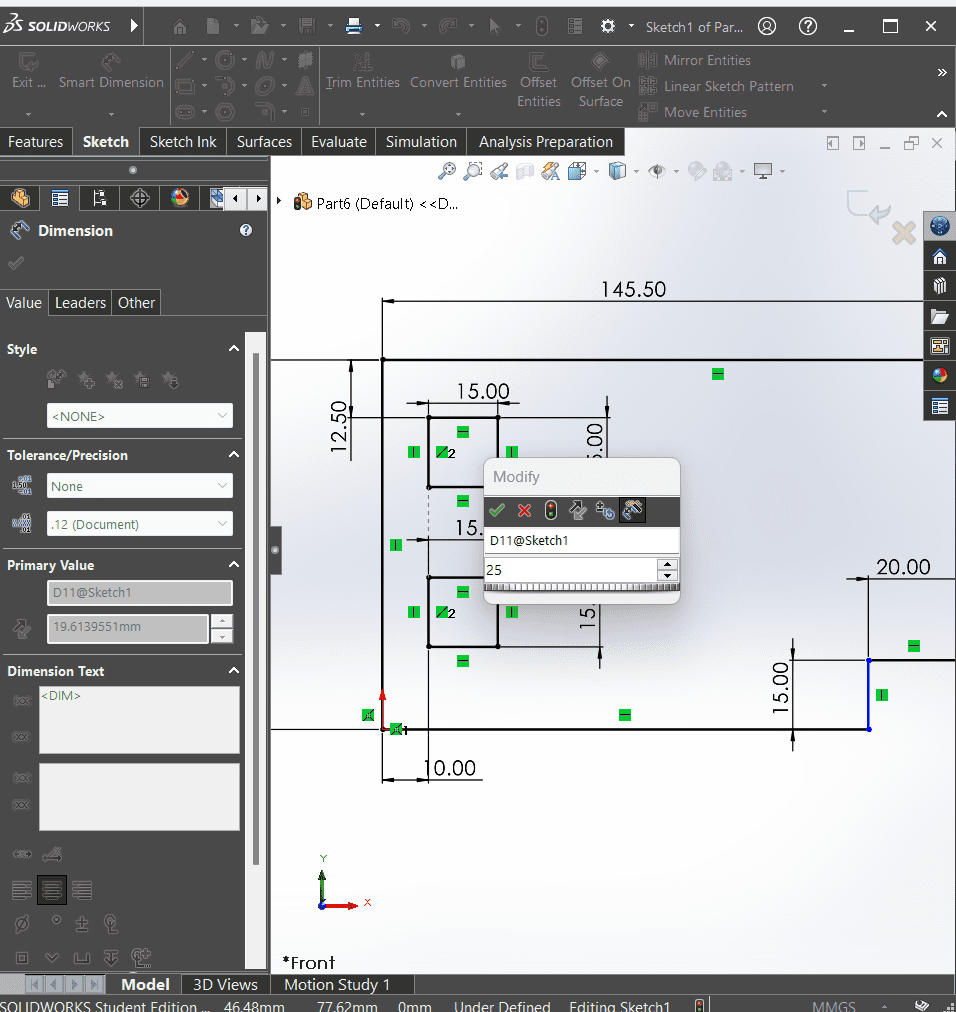
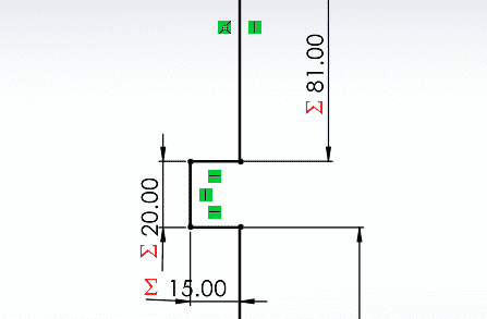
- After sketching your lines, define the dimensions of each line to specify the exact size and shape of your part. You can do this by clicking on the dimension tool and then clicking on the lines you want to dimension.
- Once you've completed sketching your lines and defining dimensions, exit the sketch mode to proceed with creating the 3D part.
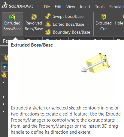
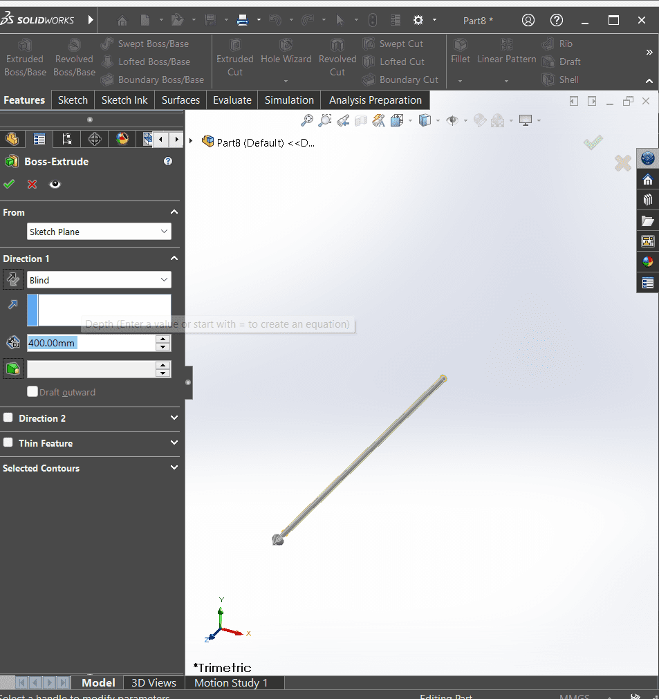
- Click on the "Features" tab in the toolbar, then select "Extruded Boss/Base" from the dropdown menu. Set the extrusion depth and direction in the dialog box that appears, and click "OK" to confirm.
- You can adjust extrusion parameters such as depth, draft angle, and end conditions to fine-tune the extrusion according to your requirements.
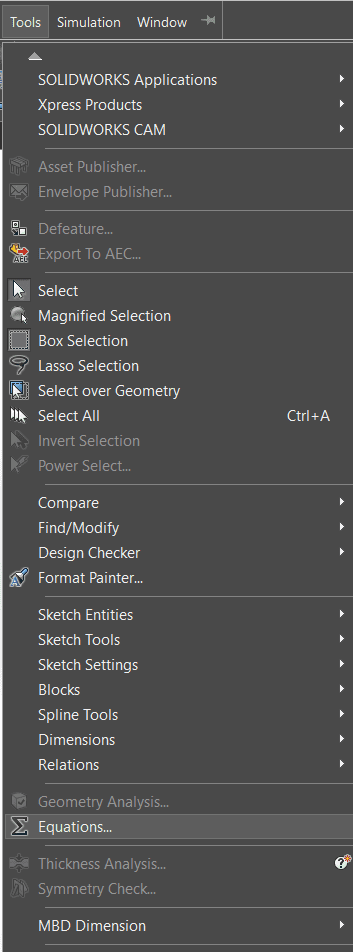
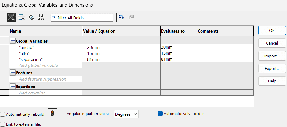
- Do it parametric!
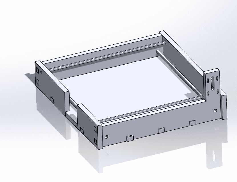
- Do an assembly of all the parts
Documents

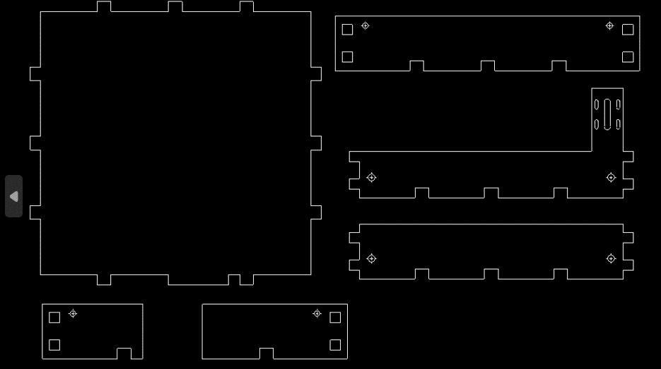
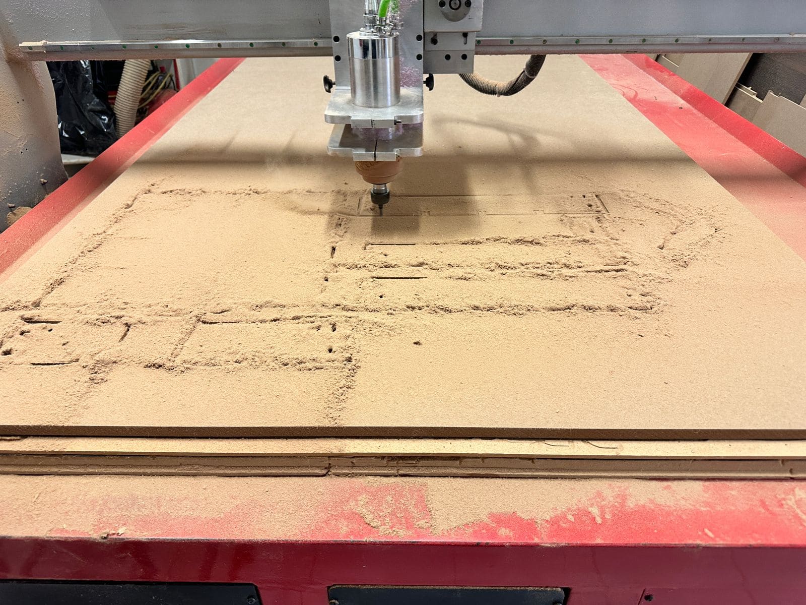
CNC cut
Here is how the parts were colocated in order to cut it on the CNC machine.
Here is an image of when we went to cut the parts.
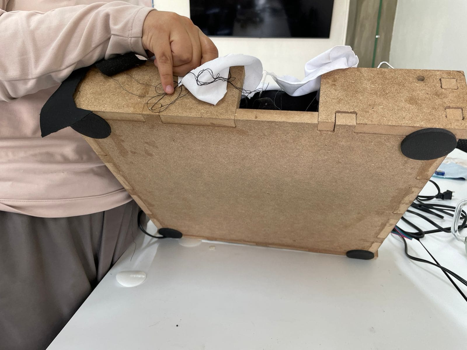
We had to use glue, in order it to be fully rigid, because the joints were not strong enough.
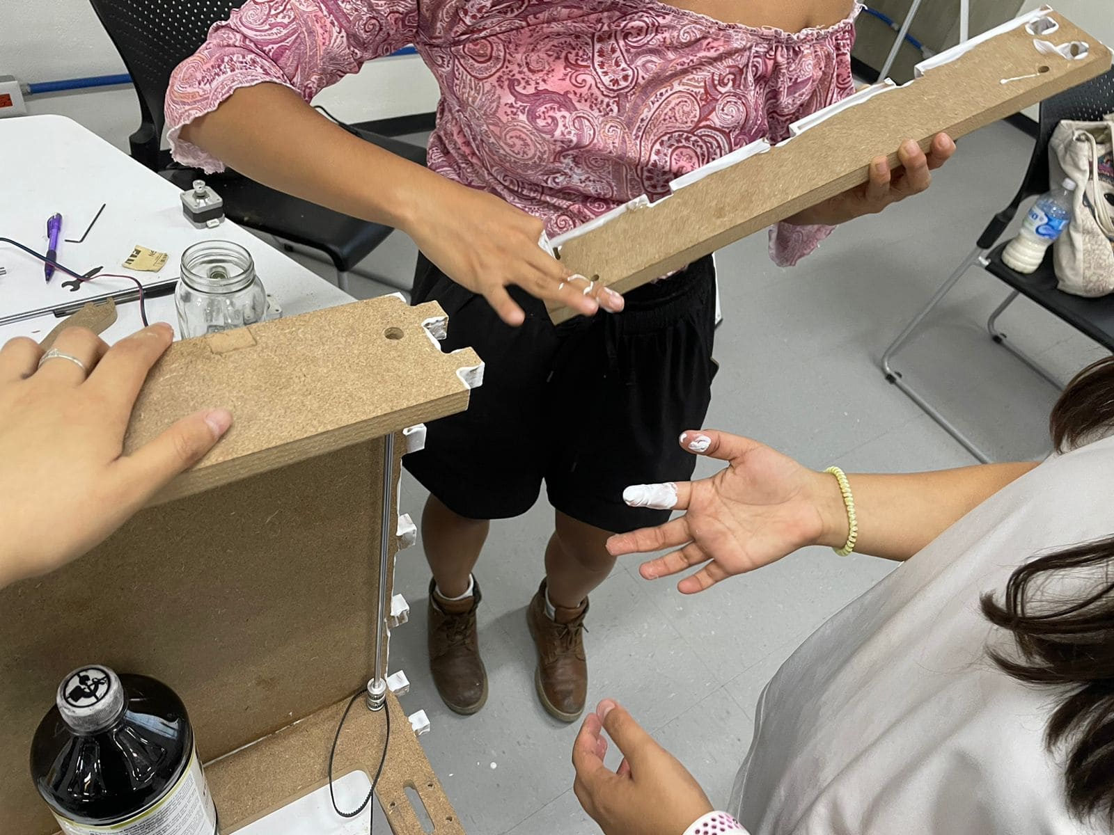
Here we are joining the parts all together.
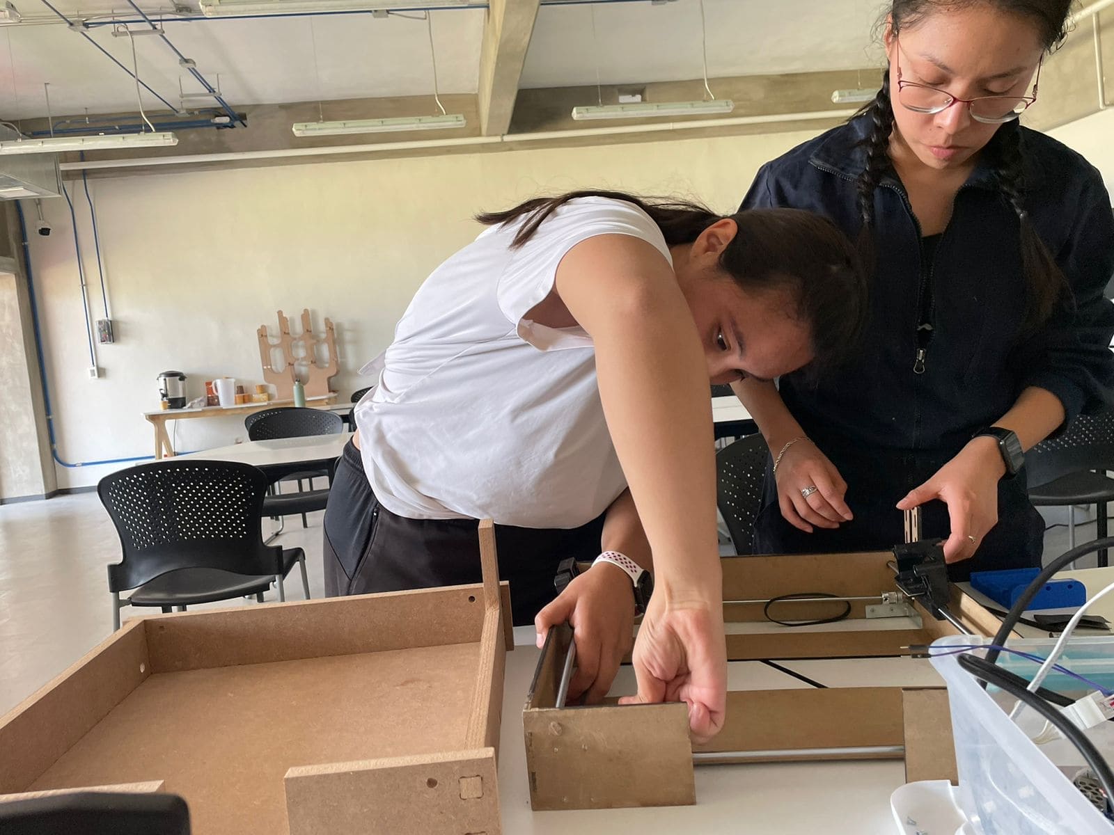
Here its a video of the process of checking everythings fits together.
| Vcarve document | G-code for putting it on the CNC machine |
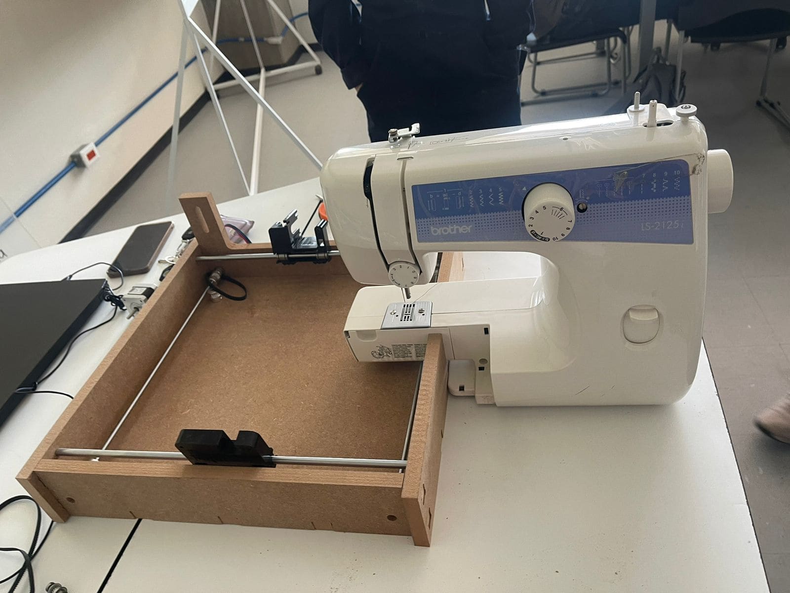
Final result
Mistakes and how I solve them
| Problem | How we solve it | First the structure we made it of 3mm MDF; and we also used some "L" brackets to provide additional support and stability to the structure.
 |
To address this issue, we decided to re-cut the machine parts using a thicker MDF, specifically 15mm thick, instead of the previous 3mm thickness. This change in material thickness provides a sturdier and more robust foundation for the machine components.
|
|---|---|
| Despite the structure being constructed from heavy 15mm materials, the persistent vibration generated by the sewing machine caused significant movement throughout the entirety of the framework. | Only a limited quantity of anti-slip patches were acquired for application on both the machinery and the framework.
  |