WEEK 10
MECHANICAL DESIGN AND MACHINE DESIGN
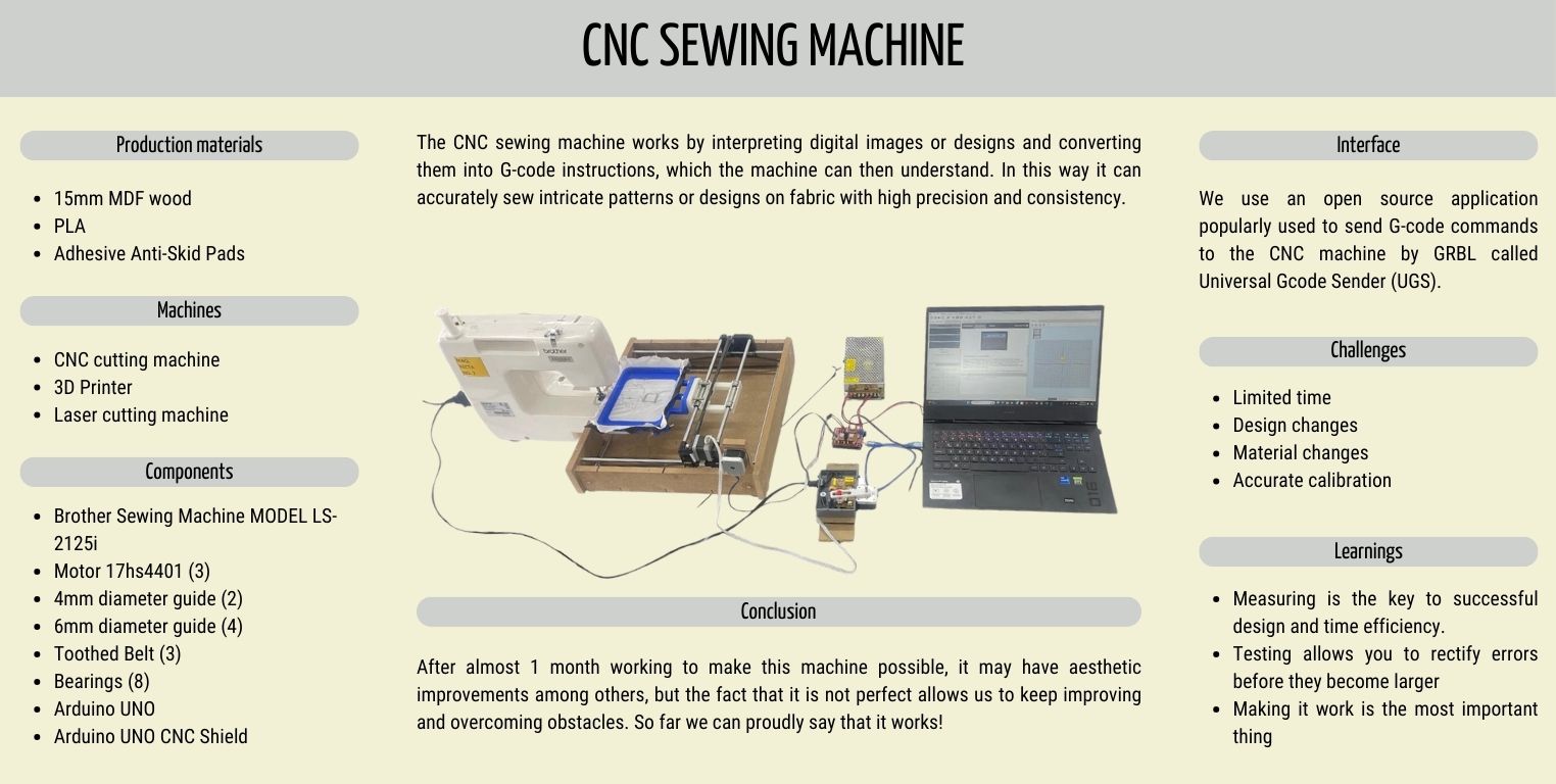
This week is about a group and interdisciplinary work making a CNC machine for sewing! It was definitely a challenging task in many aspects, I invite you to visit our group page, where you can find the details of this machine that we built together to make it possible, click here to go to our group page!
As this is a team work, in my page I will share with you what I contributed to the project from my area of knowledge which is Industrial Design, and little by little I will tell you how was this experience in a personal way.
Contextualizing the project
The idea of this machine started having in mind that the needle at the moment of sewing, would only move from bottom to top, immobilizing the Z axis, so the moving axes would be only X and Y. To do this it was decided that our CNC machine would be an adaptation to the sewing machine, with a computer controlled frame on the aforementioned axes.
Join me in designing an embroidery hoop
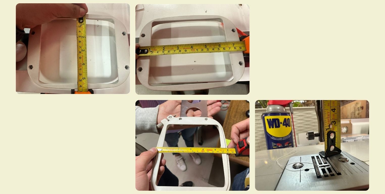
For the design of the embroidery frame I had as a reference one from an embroidery machine at the university. We chose one with the dimensions we liked, according to the size of the machine we got for this project, a Brother MODEL LS-2125i.
The first step was to take measurements of this frame, and then design our own. You might be thinking "why didn't they use the one they already had?", the truth is that I thought that we could save this step... However, being a frame from a different machine, not all its dimensions were adapted to our sewing machine, and more specifically it was too high, so we couldn't fit it inside the machine. So that was the main reason for the elaboration of this design.
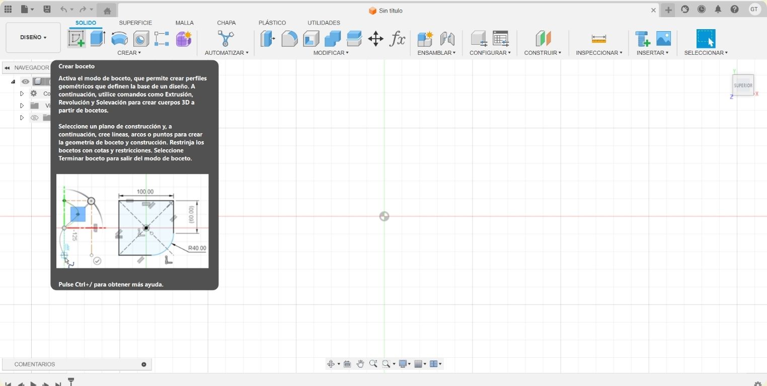
The 3D modeling program I used was Fusion 360. Lately I have liked it a lot, it is very intuitive to work with and keep track of progress.
- The first step was to "Create a new sketch" in a new file in the program.
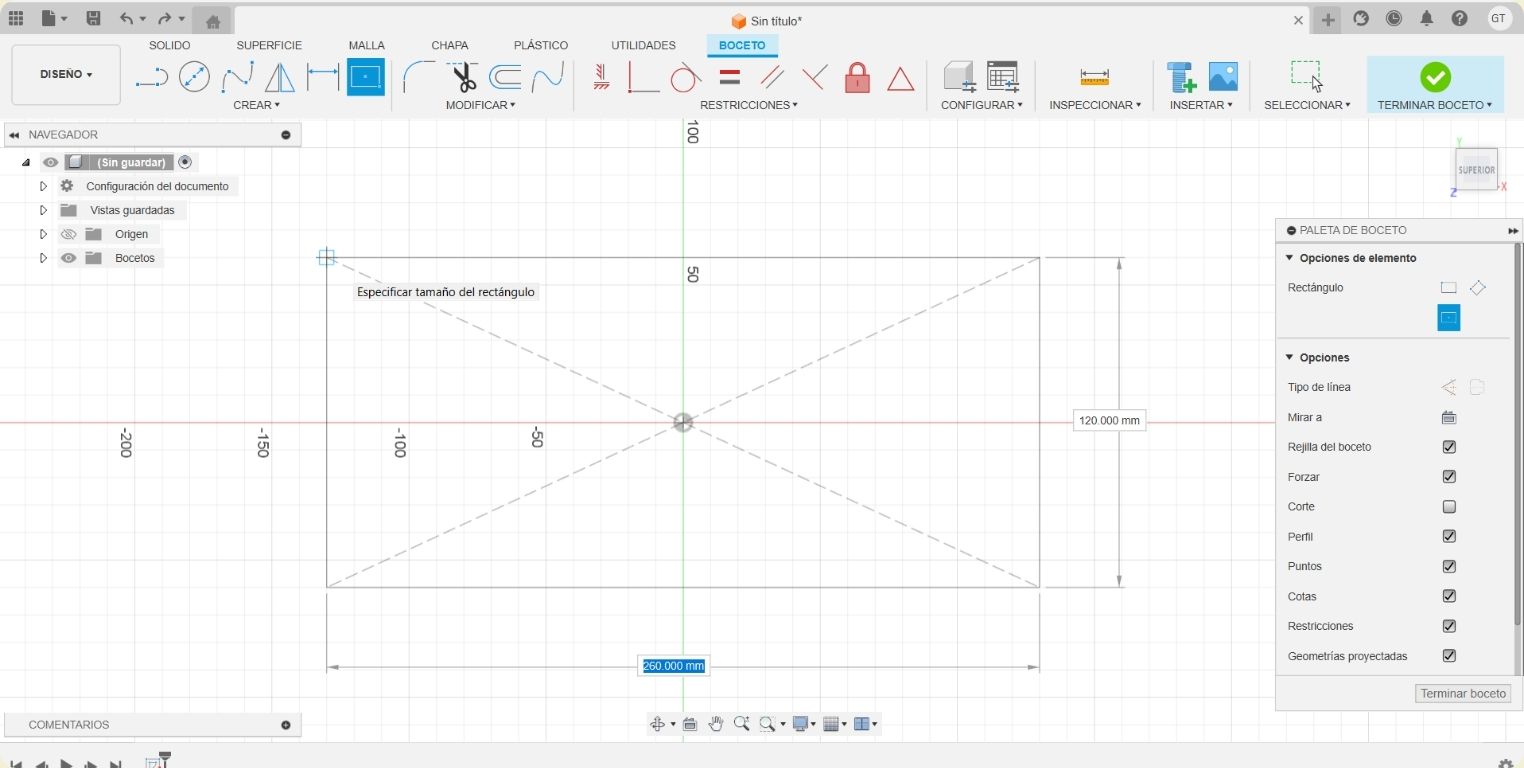
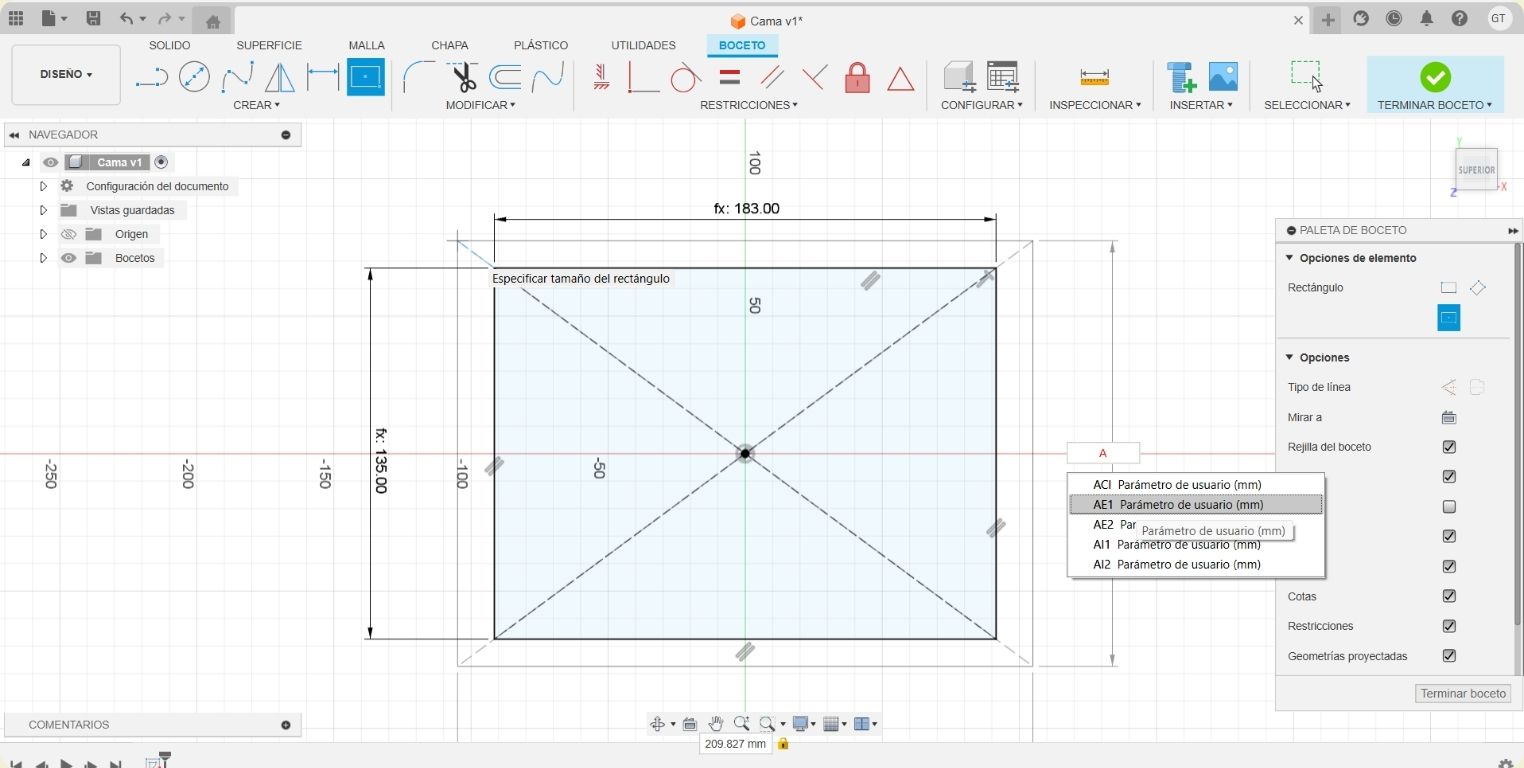
- Inside the "Create" menu I looked for the option "Rectangle by center" and made a rectangle without any specific dimension.
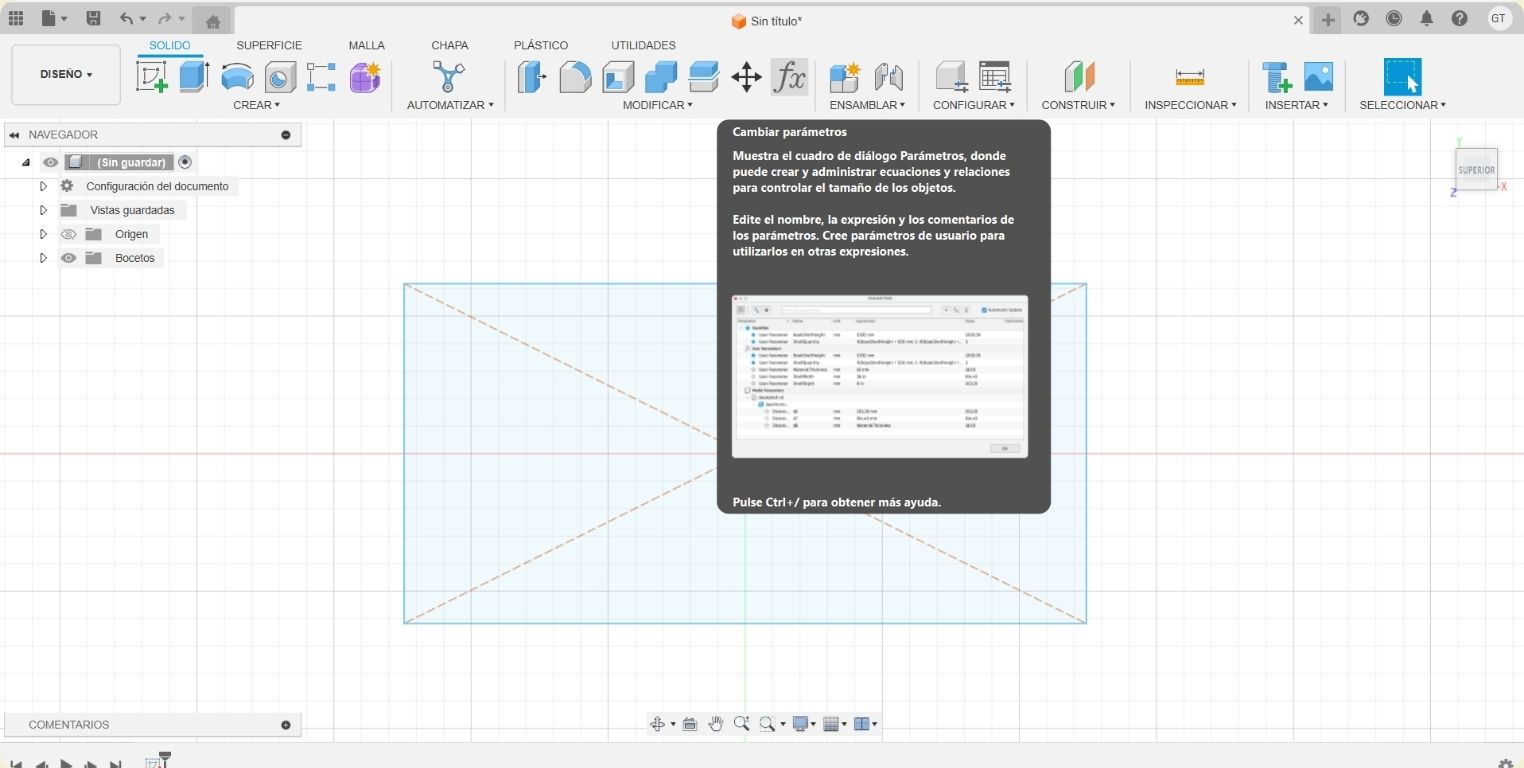
- I finished the sketch to find inside the "Modify" menu the option "Change parameters" to start setting the dimensions to which I wanted the piece to be attached, in addition to take advantage of making the parametric model so it would not be a problem in the future if I had to change the dimensions.
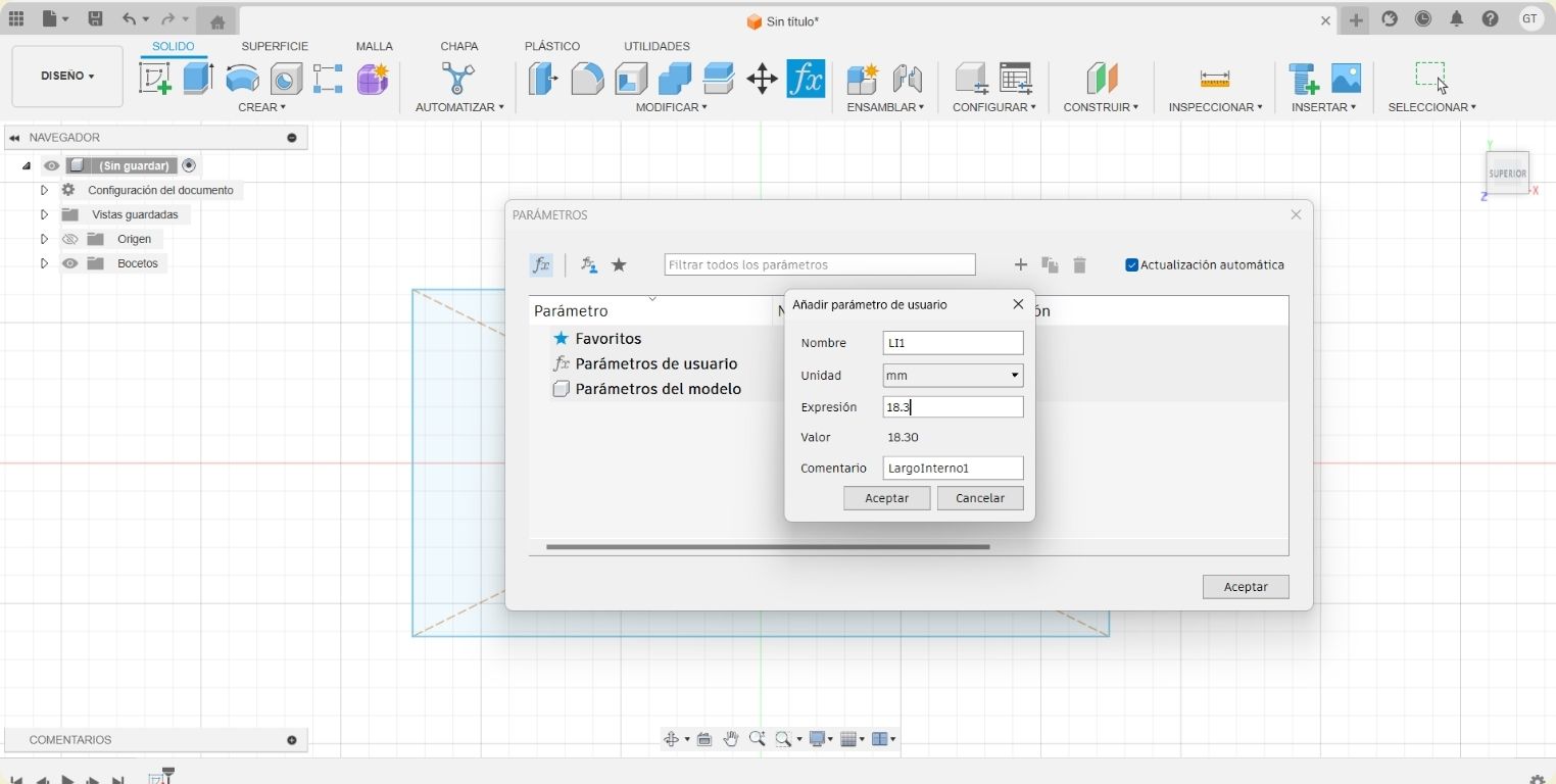
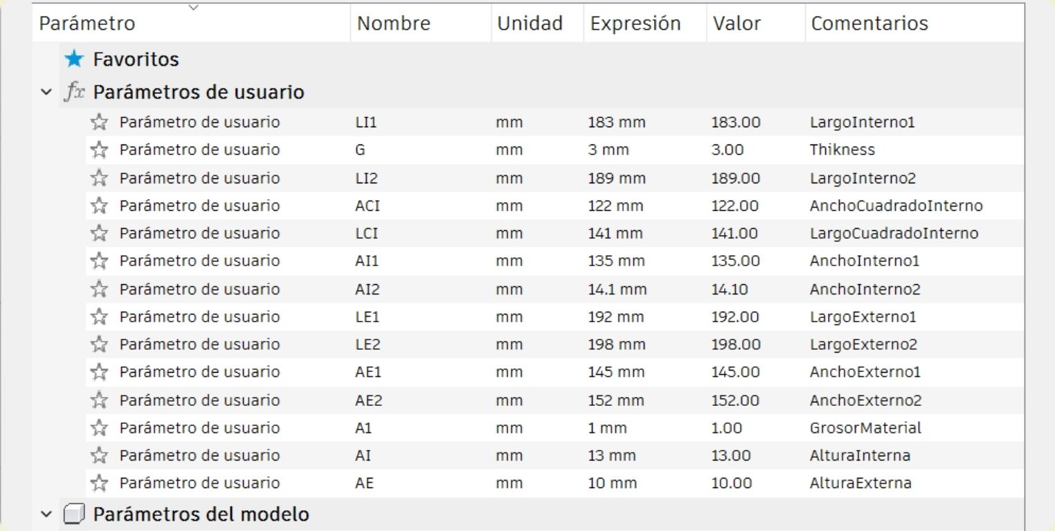
- When adding a new parameter I abbreviated its description to know what it was. In the case of the example, it was the internal length of the first part (LI1). And I always kept the measurements in mm.
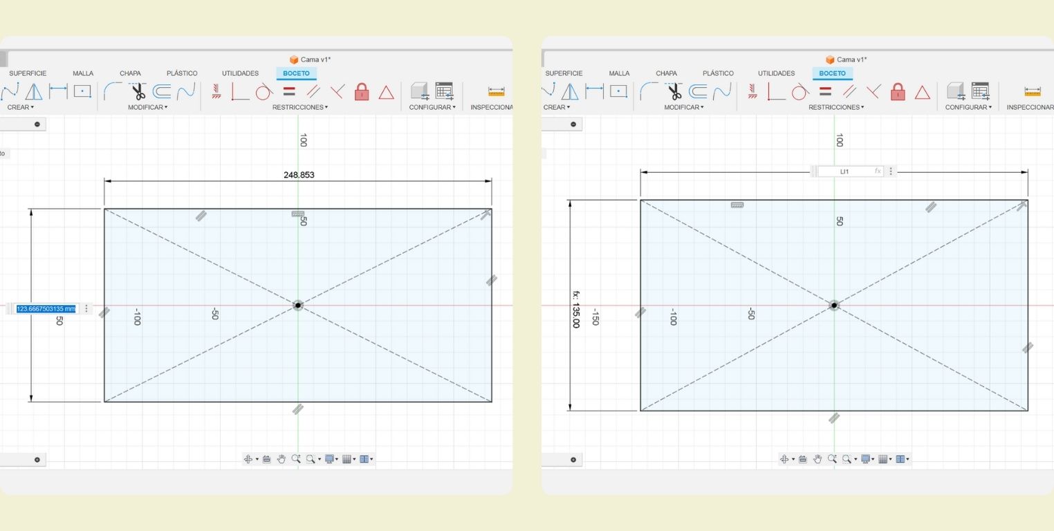
- Once I had all the parameters, I went back to edit the sketch of the rectangle I made, and I put its corresponding parameters writing the name of the parameter where previously the measurements of the figure were indicated, in this case they were the internal measurements of figure 1.
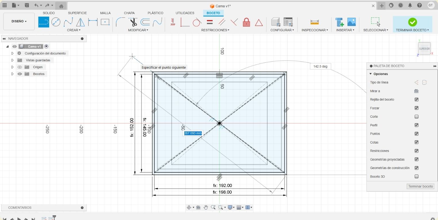
- The next step was to make a larger rectangle with the parameters of the external measurements of figure 1.
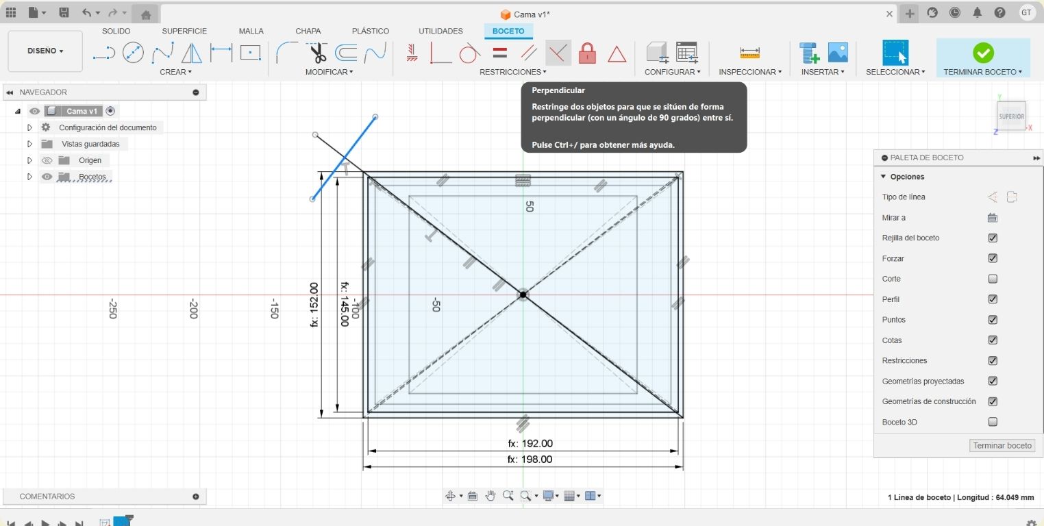
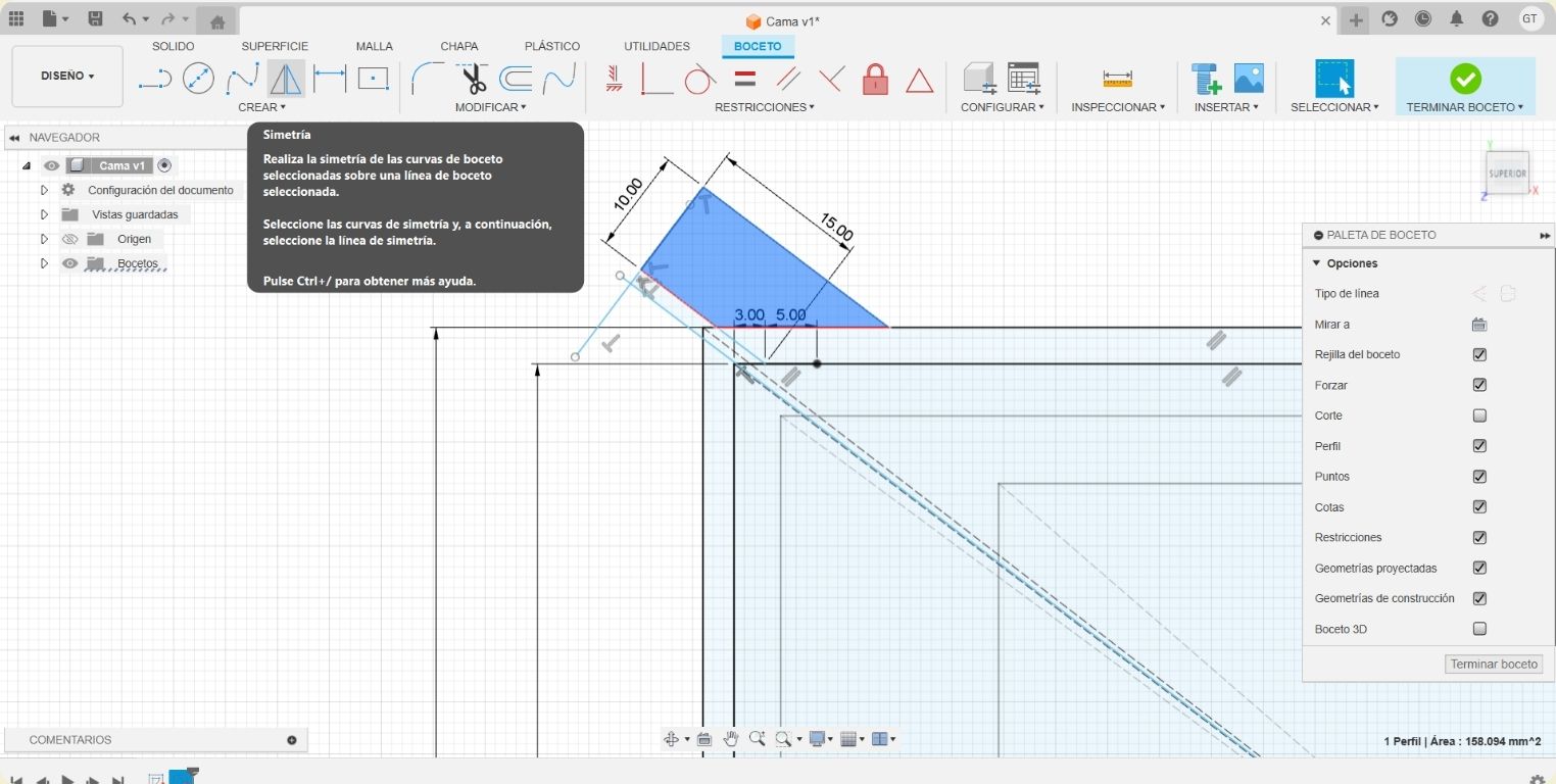
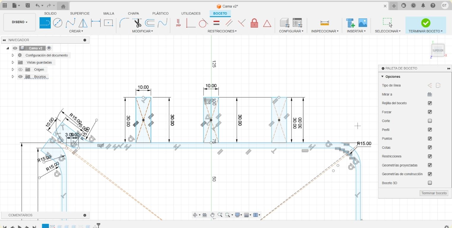
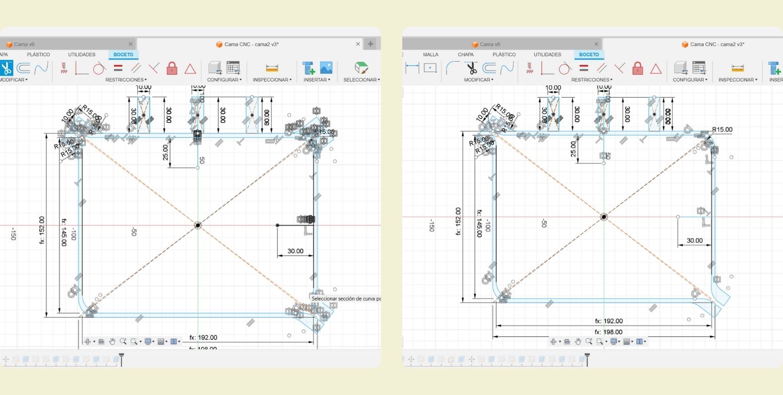
- In a new sketch I made the drawing of figure 2 with the internal and external measures of this one. In the picture you can see the measures of each one. Then I started to draw a line from the center to the upper left corner, and protruding a little from it.
- I drew another line perpendicular to the protruding line.
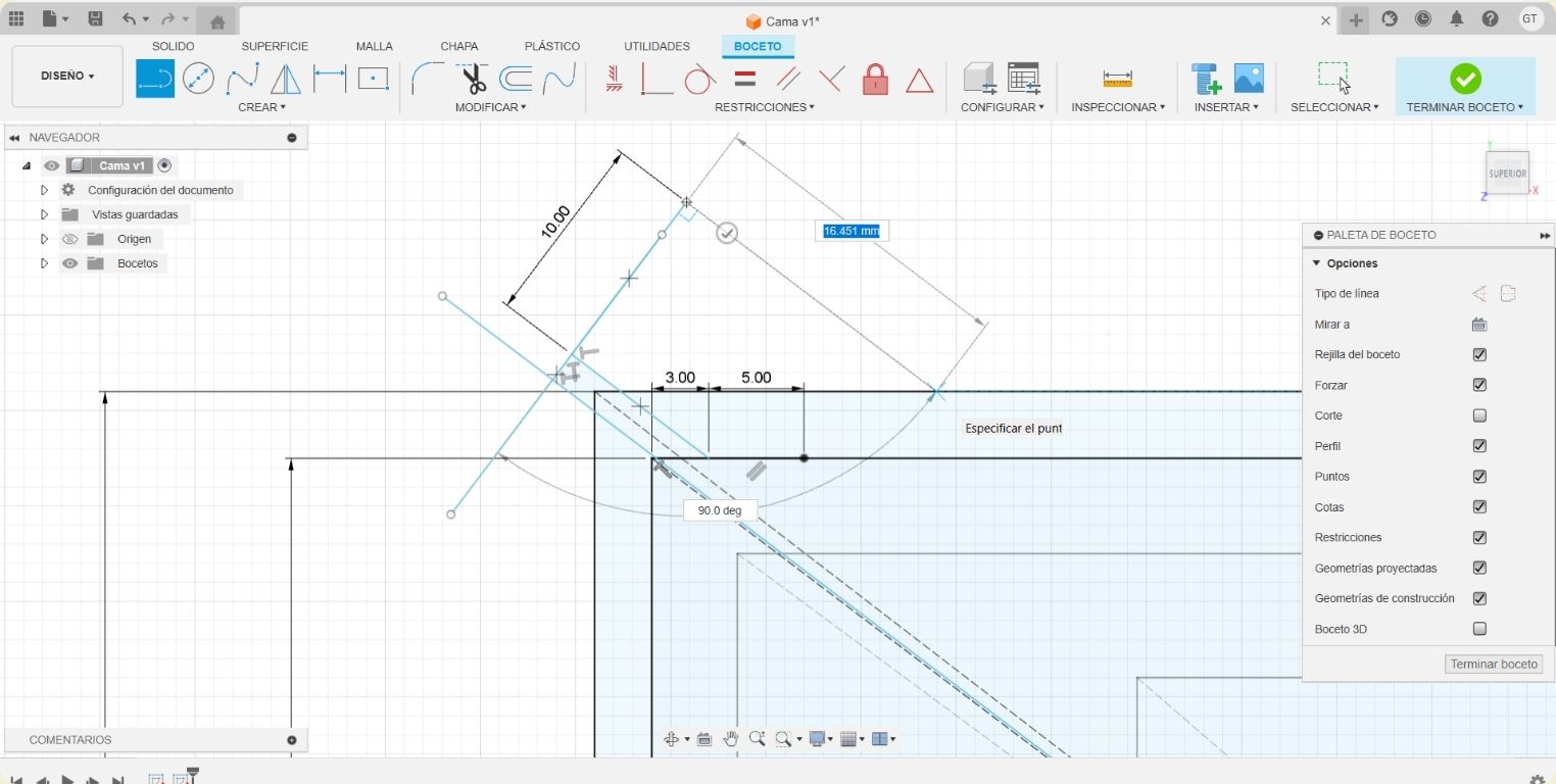
- I gave it a measure of 10 mm and at the end of this, I made another perpendicular line that I connected with the outer rectangle.
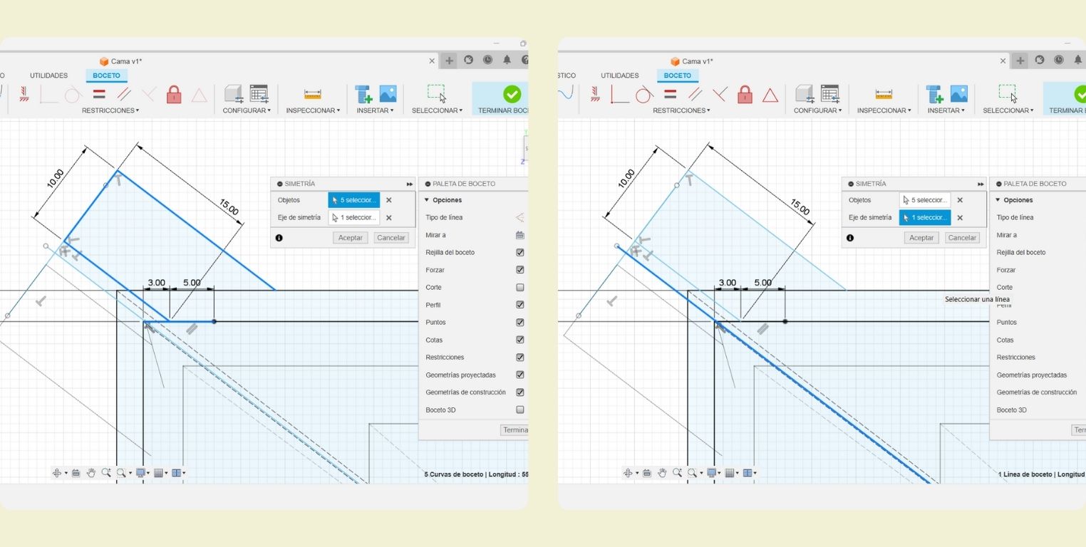
- I gave the previous figure a symmetry with respect to the line drawn before.
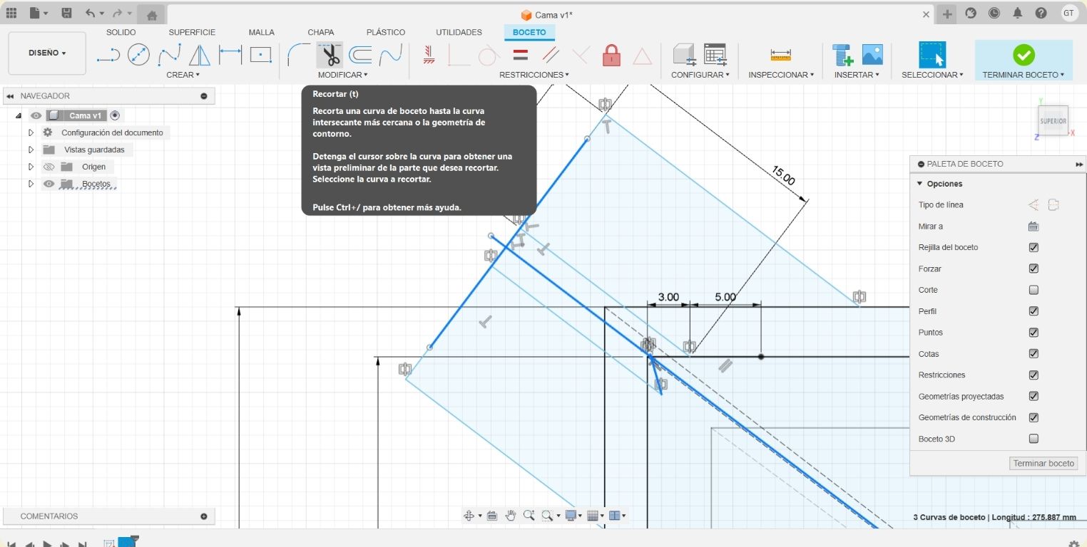
- With the "trim" tool I removed the lines that were left over from the figure.
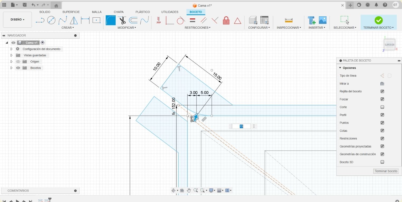
- Then with the "join" tool I made some roundings of 15 mm in the corners.
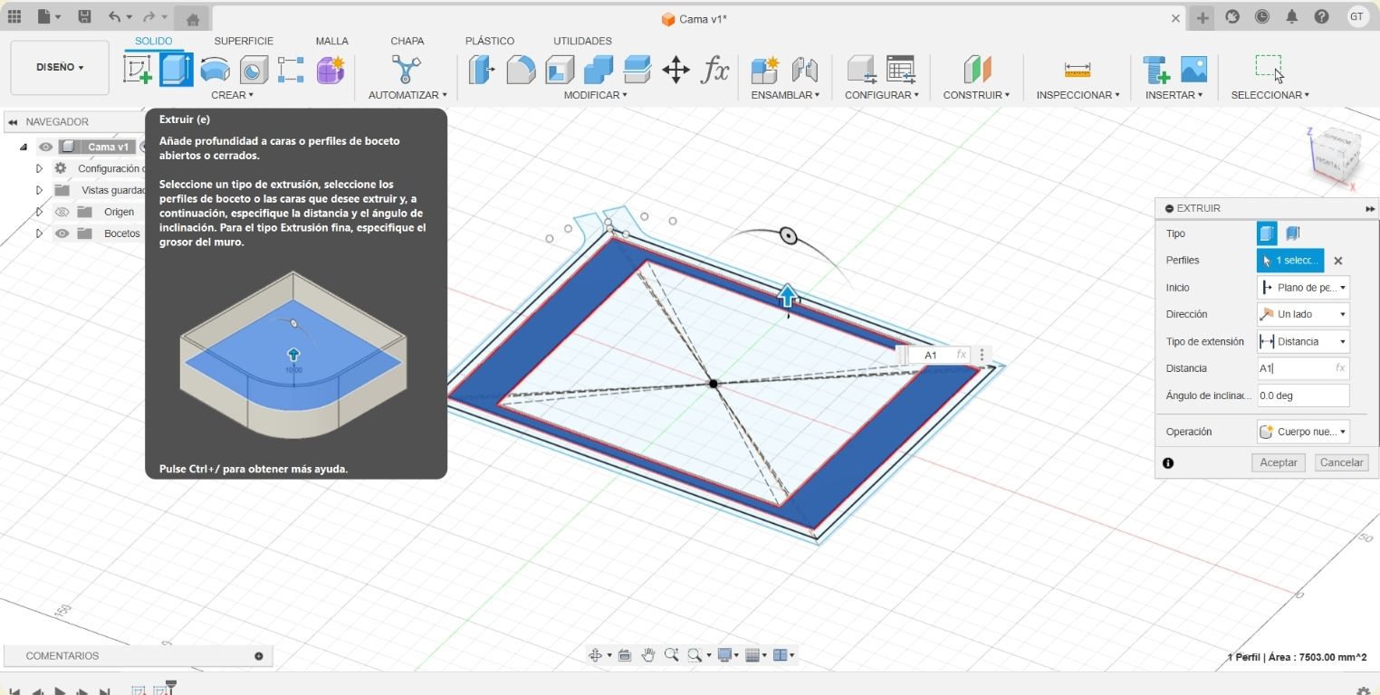
- Now it's time for everything to make more sense by extruding the pieces of the drawings. I finished the sketch and with the "extrude" tool, found in the "create" menu, I started extruding the first drawing. In the "distance" section I put the parameter that corresponded to the distance of the extrusion.
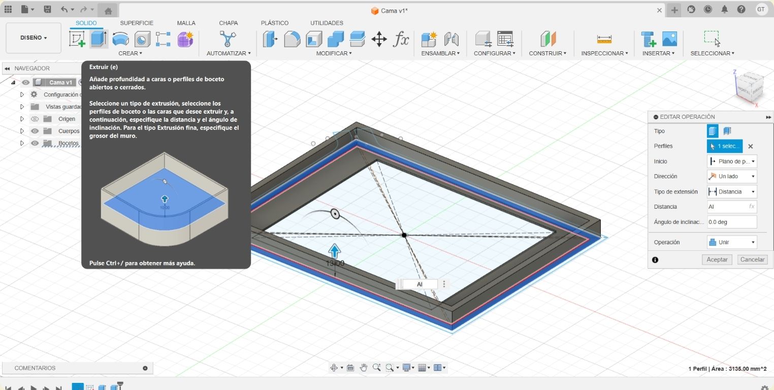
- I then made another extrusion, and made sure that in the "operation" section it was "join" so that it would join with the previously extruded part.
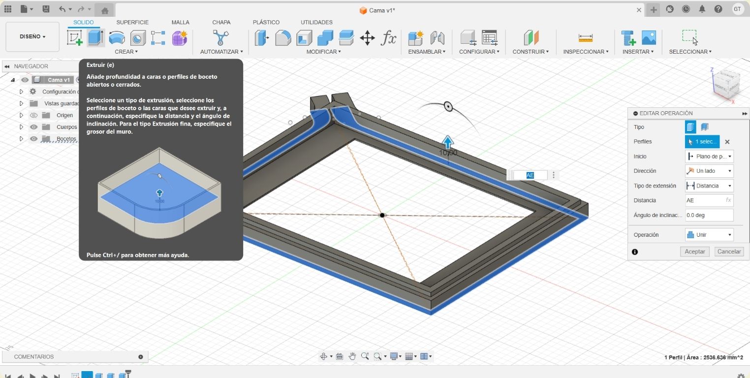
- I also extruded the last drawn part, however, in the "operation" section it should say "new part".
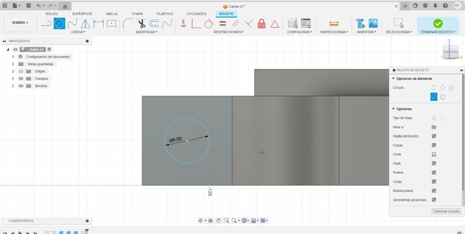
- I then started a new sketch on one of the faces of the last extrusion.
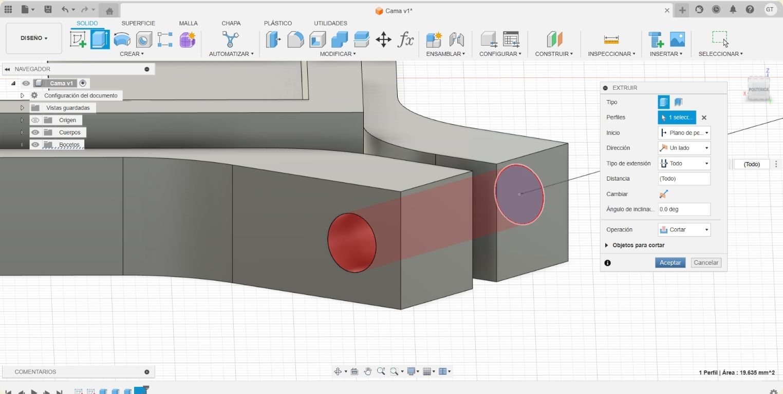
- There I drew a 5 mm circle to make the hole through which a screw will pass to fit the fabric to the frame.
- To then extrude it all over with a cutting operation.
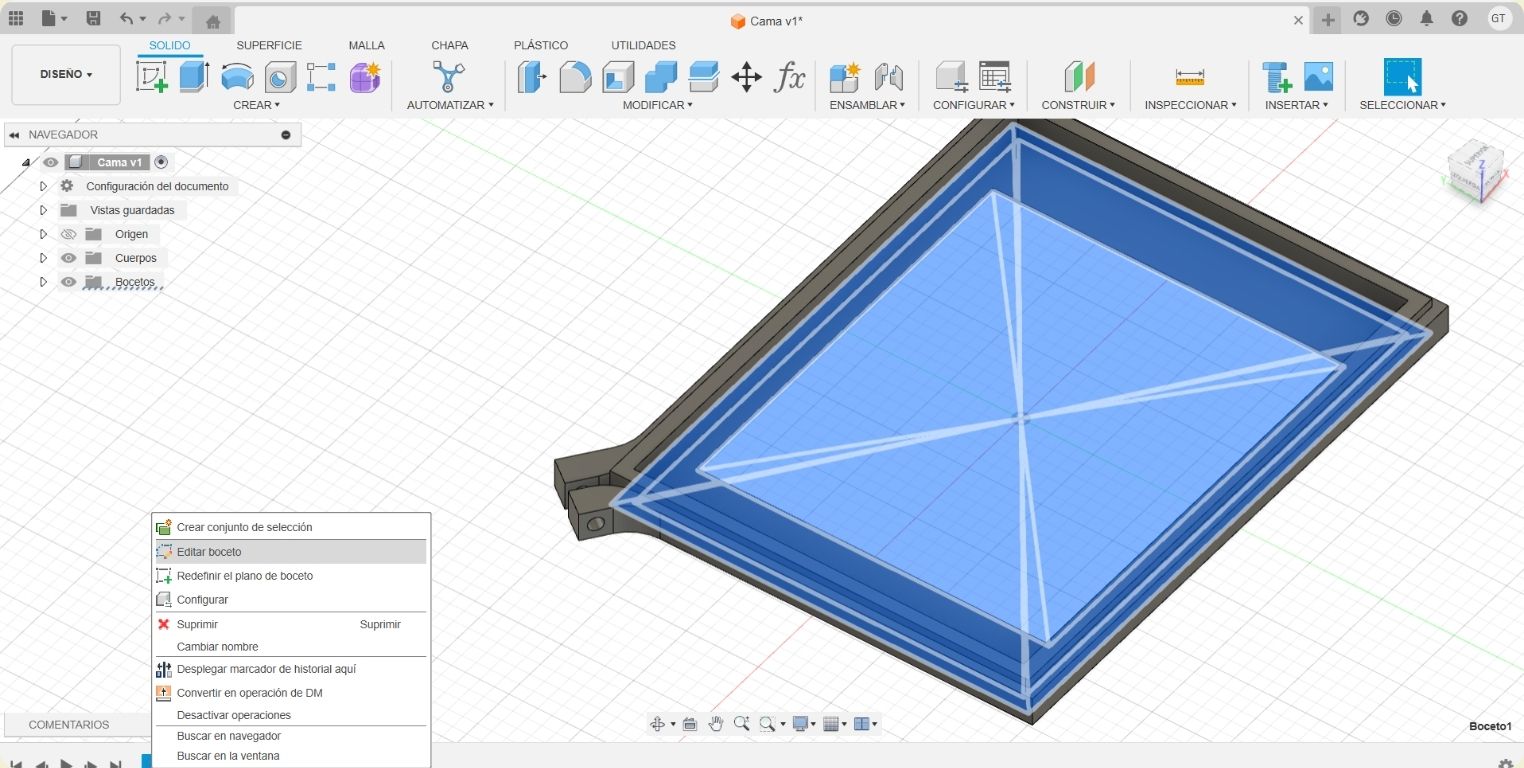
- Since there were some things I wanted to edit on the frame, I right clicked on the sketches at the bottom to edit them.
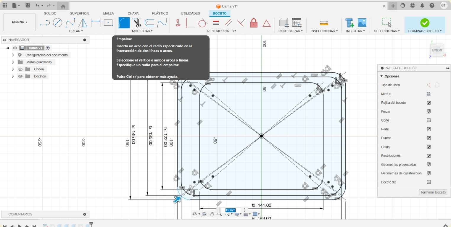
- What I did was to make 15 mm roundings on all the corners of the sketches.
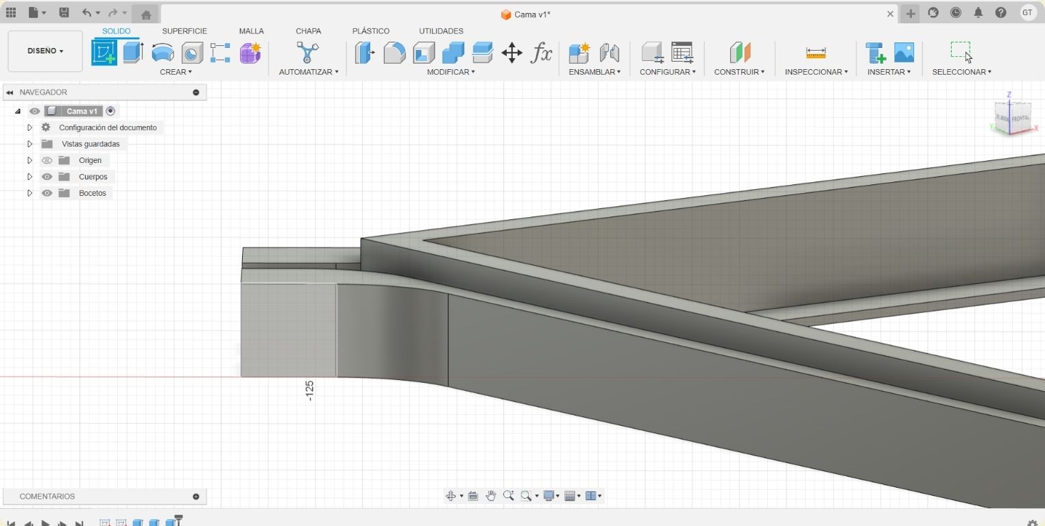
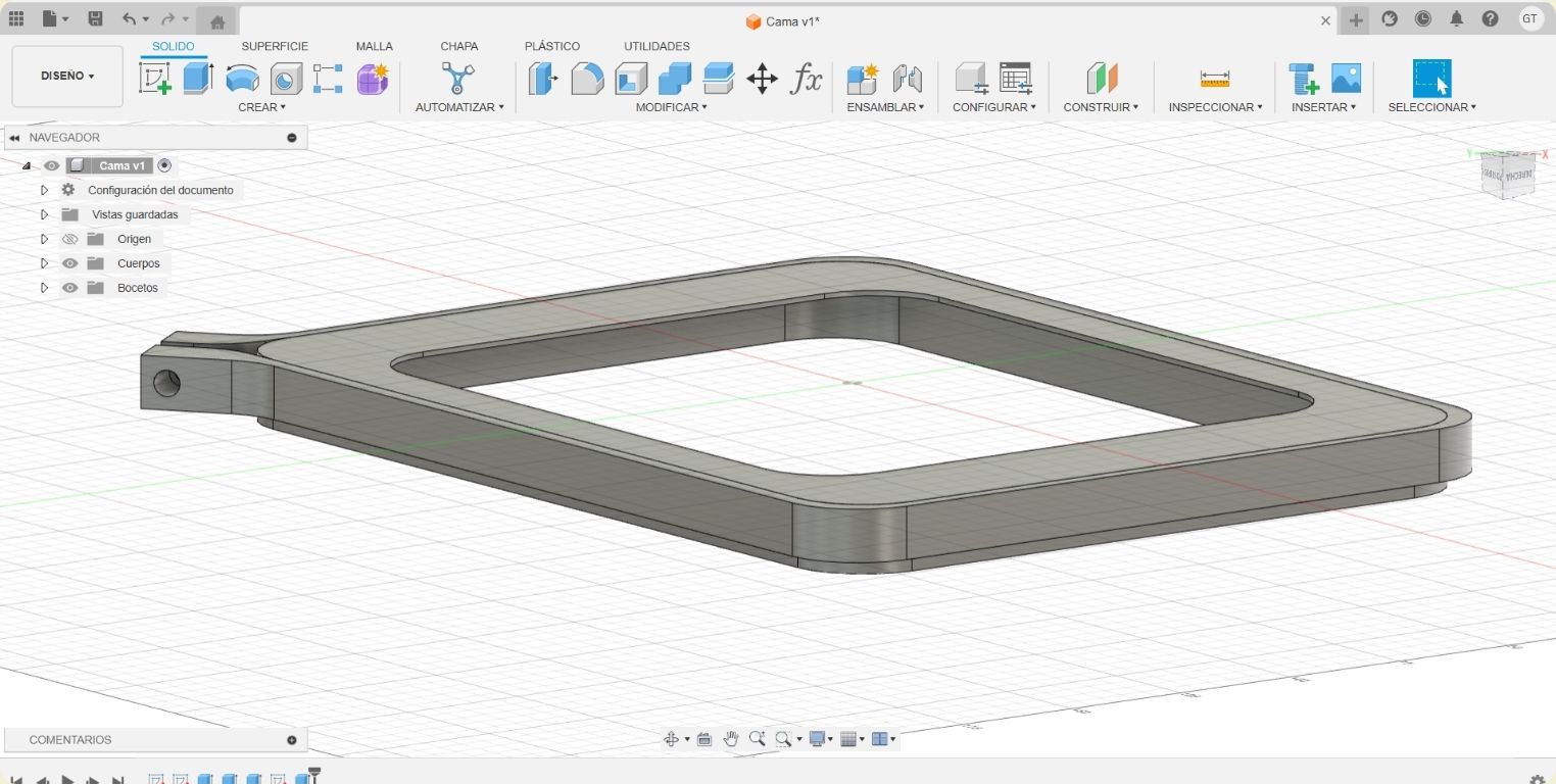
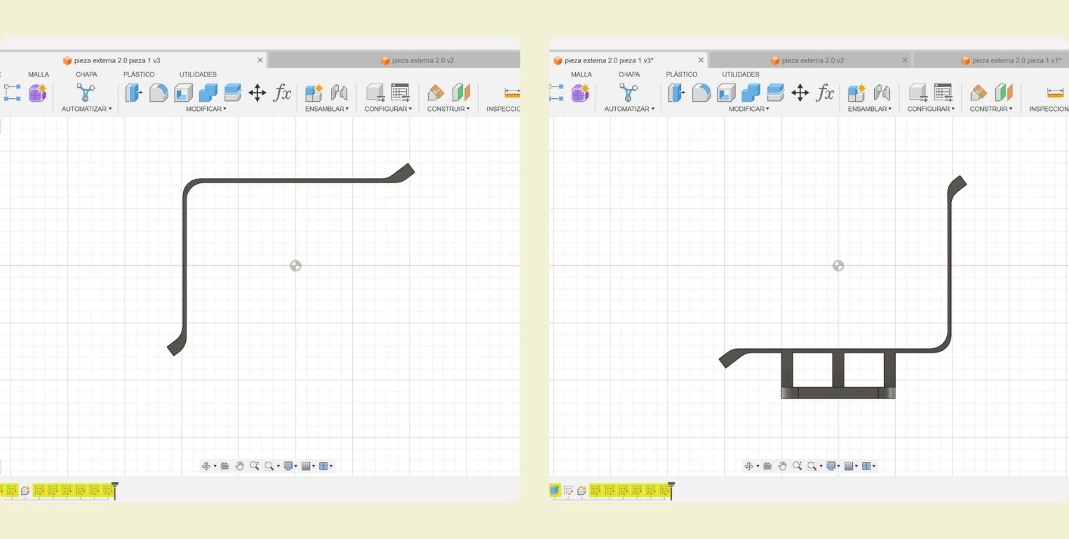
- Then it was time to correct the last extrusion I had made. As you can see in the picture, it was previously a joint extrusion, but in reality it must have been a new body extrusion.
- Here is a perspective of the frame.
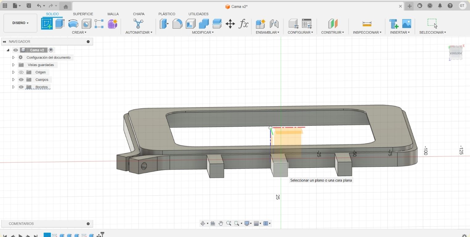
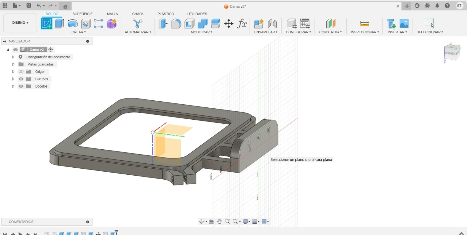
- I went back to the last sketch to make 3 rectangles at the top to make the bed piece attachable to the CNC machine.
- When I finished the sketch, the extrusion of this one was updated. And I made a new sketch on one of the new extruded faces.
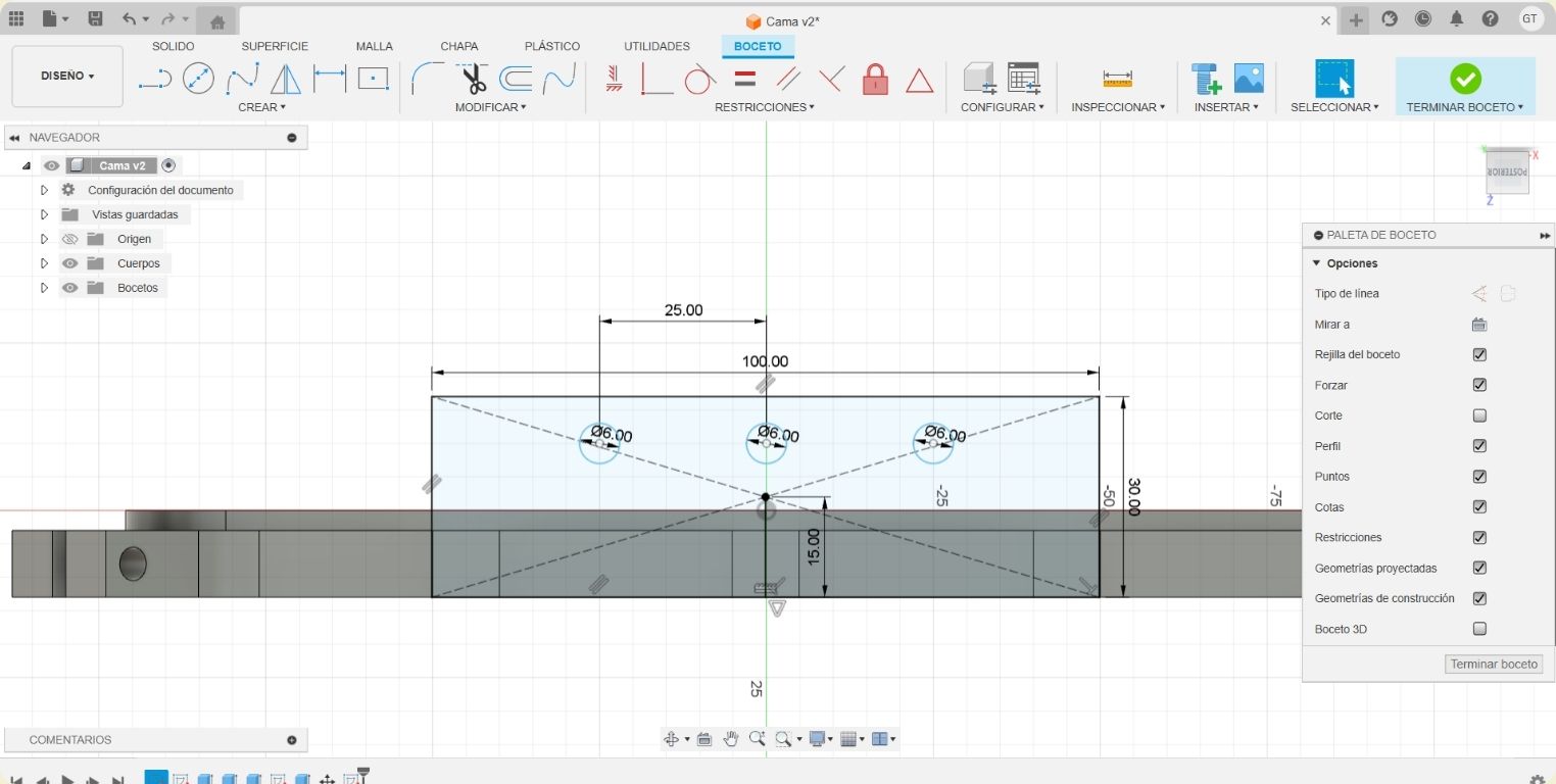
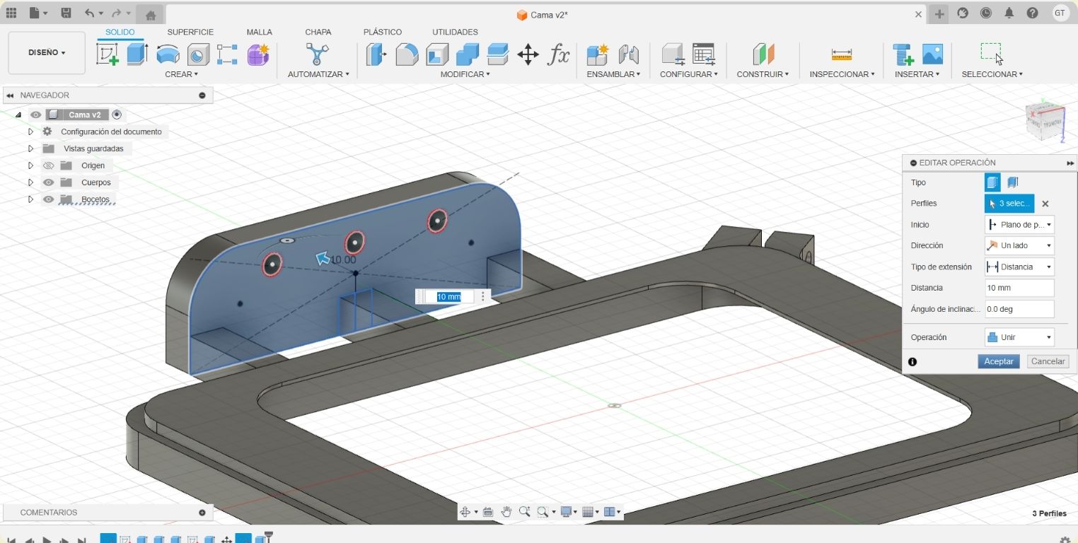
- The new sketch consisted of a 100*30 mm rectangle with a 15 mm corner joint and 3 6 mm circles.
- This last sketch was extruded outward 10 mm.
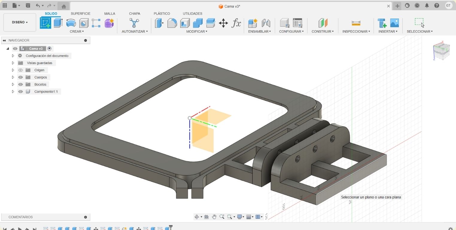
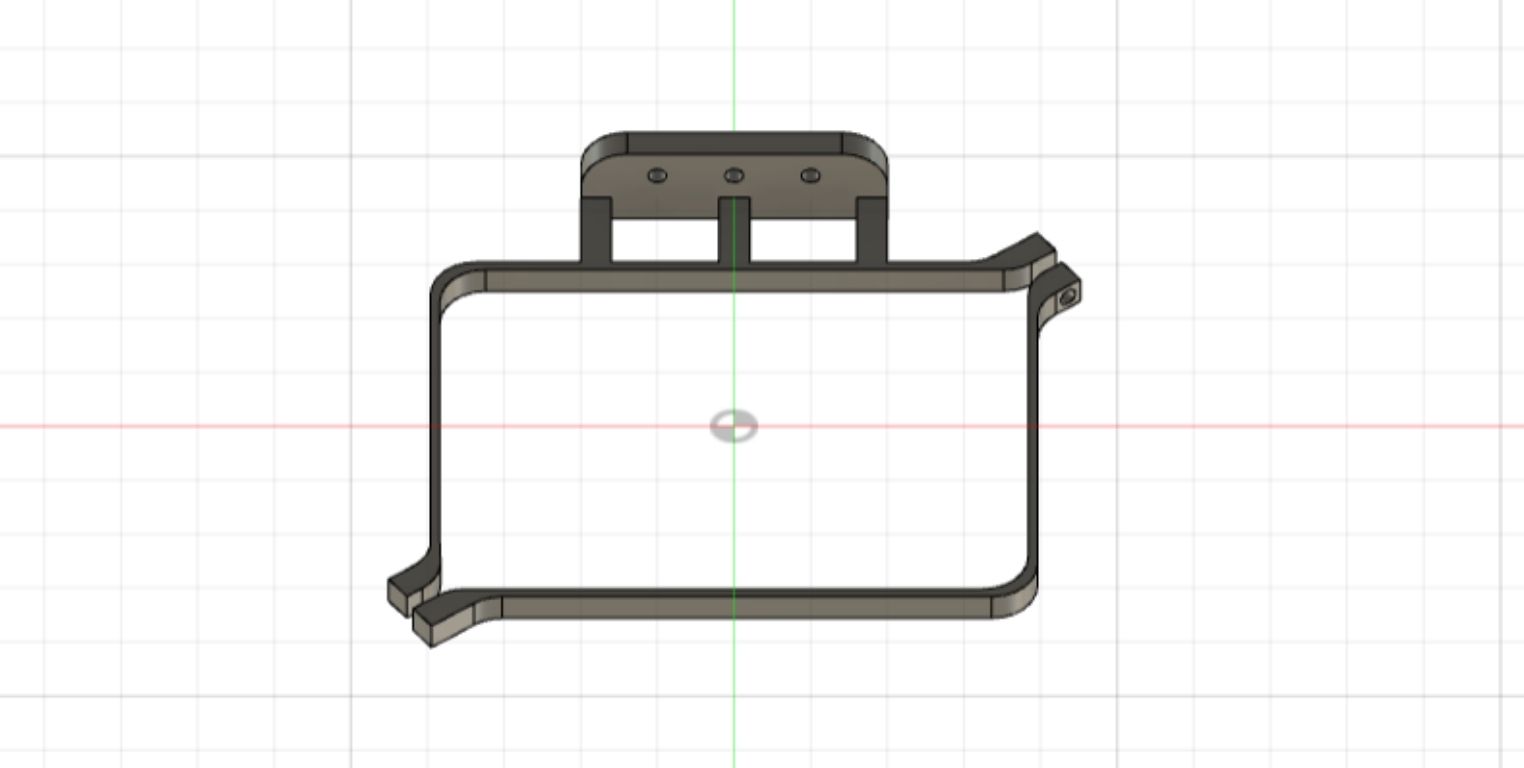
- This is what the 3D model of the frame looks like.
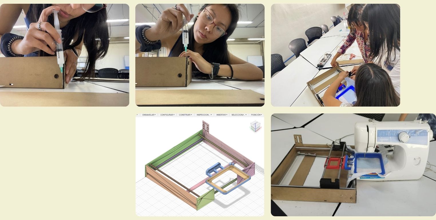
- This is how the assembly was intended to be with the CNC machine.
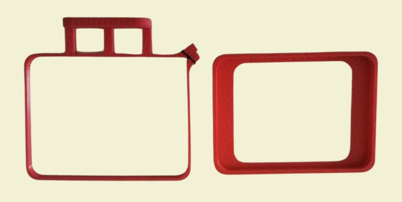
- This was the first print we made of the 3D model, however, the machine had a calibration problem that we did not notice before, so the print had come out a bit "weak". So we reprinted it in blue.
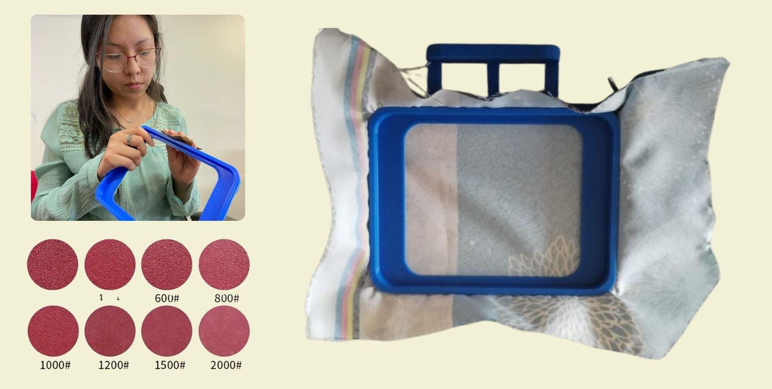
- As one of the first things we had was the frame, we did an initial test with it, because an instructor told us to check if the machine baked when we moved the frame with our hands, if it did it meant that then we could make it bake with an interface that moved the X and Y axes. And so it did, this was the final result, do you also find resemblance to a face?
- Once the new print was ready, removing the small stand from the base was a more complete task, as the print itself had more structure and strength, so I had to sand the interiors and interiors so that the pieces together would fit together smoothly. From someone who has sanded his entire college career and also finds pleasure in it, I recommend you first do with a wood sandpaper a higher grit, and then move on to a smoother water sandpaper to achieve a roughness-free, even surface. Coarse sandpaper has a smaller number, while smooth sandpaper has a larger number, as in the example photo.
Anything on electrical engineering?
Contributions are equally valuable and no matter how small are... I helped with something very basic to my colleague Luis here, but for me it was relevant, so I share it too. What we were doing was the plug to connect the whole CNC machine to the power. And is that at first we could not manage to tangle the cable and adjust it with the screw. So I helped Luis to put tin on it so that the ends of the wires would have a better structure because they were glued together. Once this was done, I helped Luis to do the next step and positioned the wires with their respective screw. It was definitely not difficult or complicated, maybe it helped that I have small hands and unlike Luis I could manipulate the wires better.
Structure
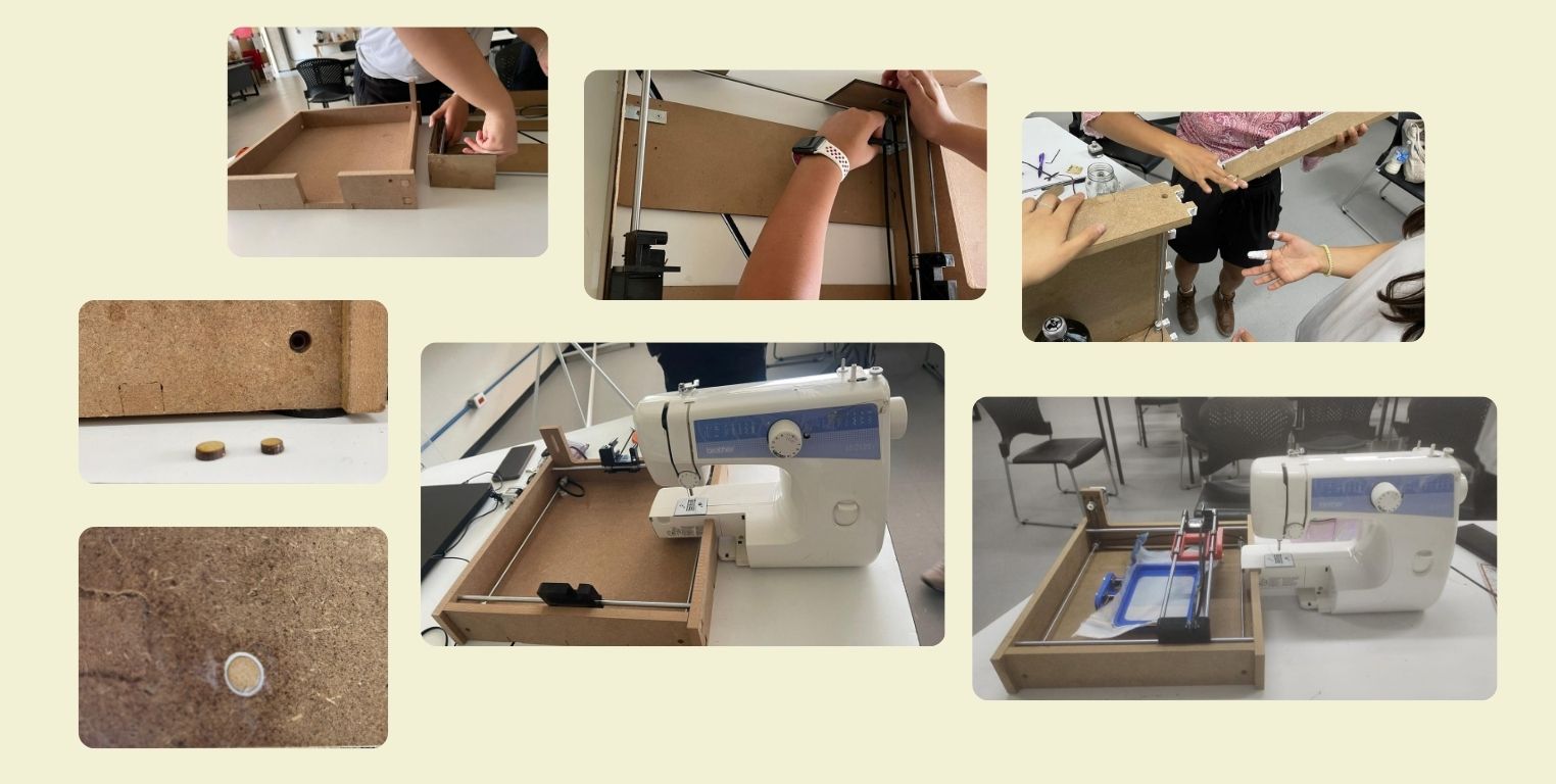
For the structure I was working at first with Olaf, one of my colleagues. We did what he calls "reverse engineering" with an old 3D printing machine that he practically ended up donating to the team, and why? Well at first we thought of using profiles to run the CNC, however, Olaf also offered us his components, so we took the latter.
Then, Olaf did the task of measuring and making a blueprint, which I could then follow to make the drawing in Fusion 360 and we could laser cut that same day. I have to say that this moment made me keep in mind how easy it is to forget something if you don't practice it... Approaching a laser cutting machine again was a strange experience because it took me longer than usual to cut, but also our machines at the university have suffered breakdowns due to misuse, so I think it worked against me a little bit.
At the time of assembly it seems that there were some problems that we may not have considered either of us before. However, I was not present at the team meeting that morning, and when I joined them they had gone back to doing everything from scratch in SolidWorks... It probably would have been better then to have done this in SolidWorks instead of Fusion 360, as it is the program they are all more proficient in... This is the sign they needed then. If you plan to do something as a team and pass the files to each other for editing, you need to make sure that it will be the same program that you will all use, or at least that you know how to use it, and at the very least that you can be there when they need to make modifications and that you can make them.
But regardless of that, for the afternoon that I was able to be present, Brenda, Ximena and I continued with this process. IMPORTANT: You have to measure very well and always rectify measurements, because I think it is better to do this than to cut a thousand times and end up wasting material, although sometimes it does happen with prototypes.
A few assembly tests later, and we started to glue the pieces with the help of C presses. As at the beginning we used 3 mm MDF and this was not stable at all, we reinforced it with another layer of MDF to make 6 mm pieces, but the structure still moved a lot... So we used some metal "L's" to help give structure, then a few metal pins and a wound later (nothing serious) we were close to finishing the structure (at least we thought).
To glue the pieces together we used white resistol, and for the joints and parts that were harder to reach I used a needle with glue. This is a great tip I give you, it can be really helpful when by yourself you can't put glue where it is needed without messing up the aesthetics because of the glue. And well, after it is completely glued, even from the smallest corner we begin to introduce all the pieces. Here you can see how everything is assembled.
Deep down I already knew that this structure was not going to hold, because it was very thin, however, we invested a lot of time in it, so I kept my hopes high that it would work... In the end an instructor told us that it was better to do it with 15 mm MDF that we had to cut in a router, so we decided to take into account the previous structure as another prototype, to make the final structure.
For the pieces of the new structure, we started from scratch, taking into account the measurements of the prototype we made. All the pieces were cut on the Router, but there was a piece that had to be recessed, and from this point the easiest thing to do would have been to cut that piece again, however, I did it by hand with the help of a Mototool. I made the recess taking into account the height at which the engine would go, and I marked it with a pencil to have the reference. In the lower right corner you can see a picture of me covered with MDF dust. Then I changed the sanding tool of the Mototool and put a tool to make the holes for the screws to which the motor was going to be attached.
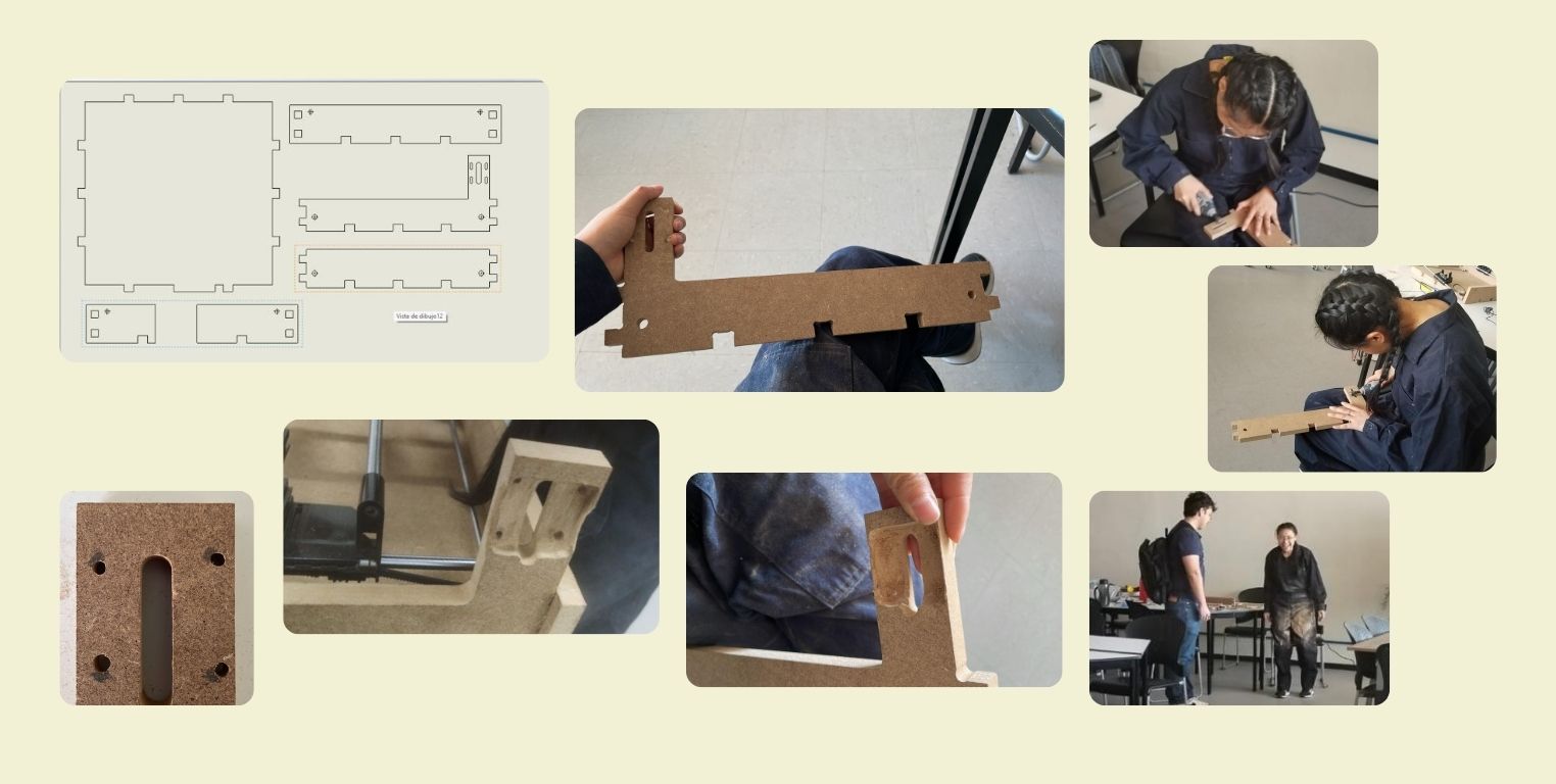
Initially when all the pieces were ready, they were assembled without glue to verify that they all fit together correctly, after that we started to dismantle the previous prototype to assemble all the components in the new structure and verify that everything was correct. Once we made sure of that, with Resistol we started to glue the whole structure, here is a tip, you can clean the glue, you can do it easilly with a paper and some water. The next day, to prevent the guides from coming off, I made a circle file in Illustrator and cut it on the laser cutting machine to fill in the gaps so they wouldn't come off anymore. See the level of detail in the bottom left photo.
Last minute resolutions
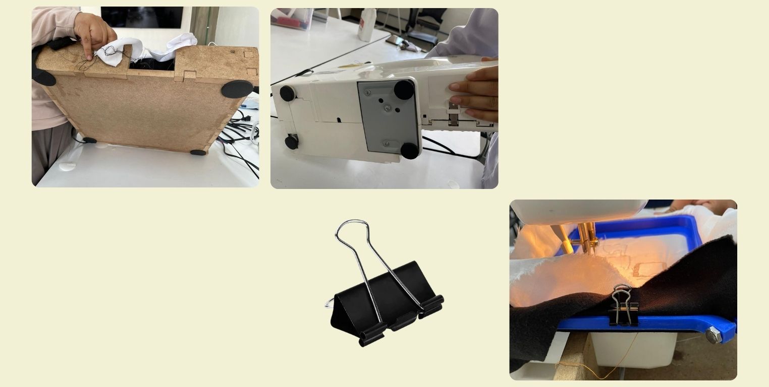
At the end of the tests, we can say that the CNC machine was already working, it was already firing. But the sewing machine vibrated a lot and caused the MDF structure to move. In the end we solved it with Adhesive Anti-Skid Pads under the frame and the sewing machine. They really helped considerably to decrease the vibration of the CNC.
It also detected that this was causing the fabric to loosen from the frame. So to prevent that from happening in the final test runs, we improvised by putting paper clips on the edges of the frame.
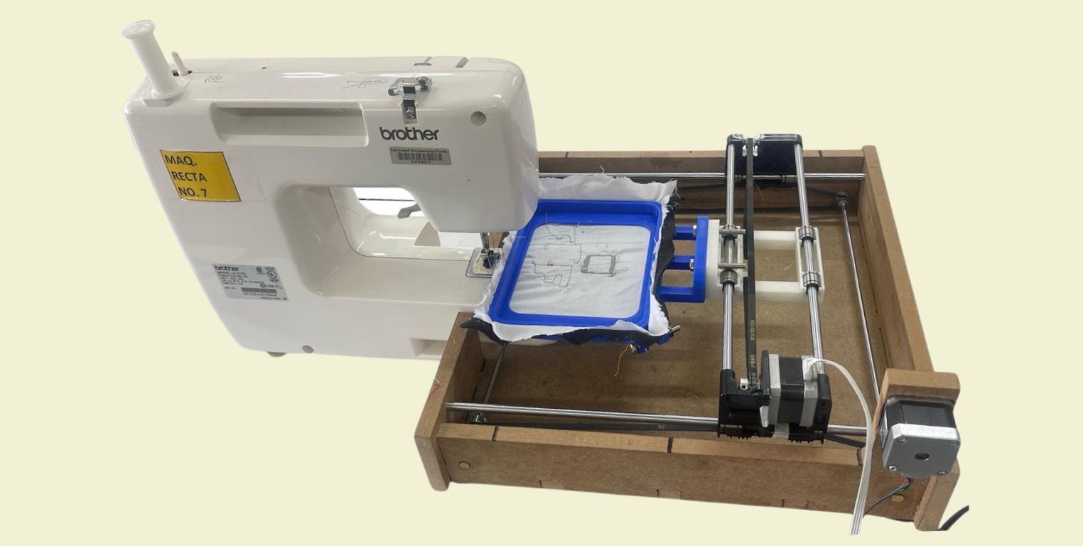
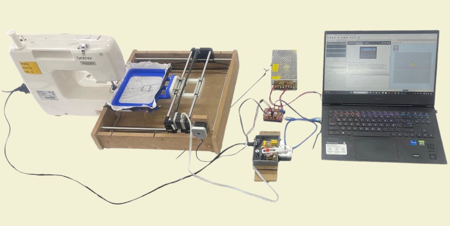
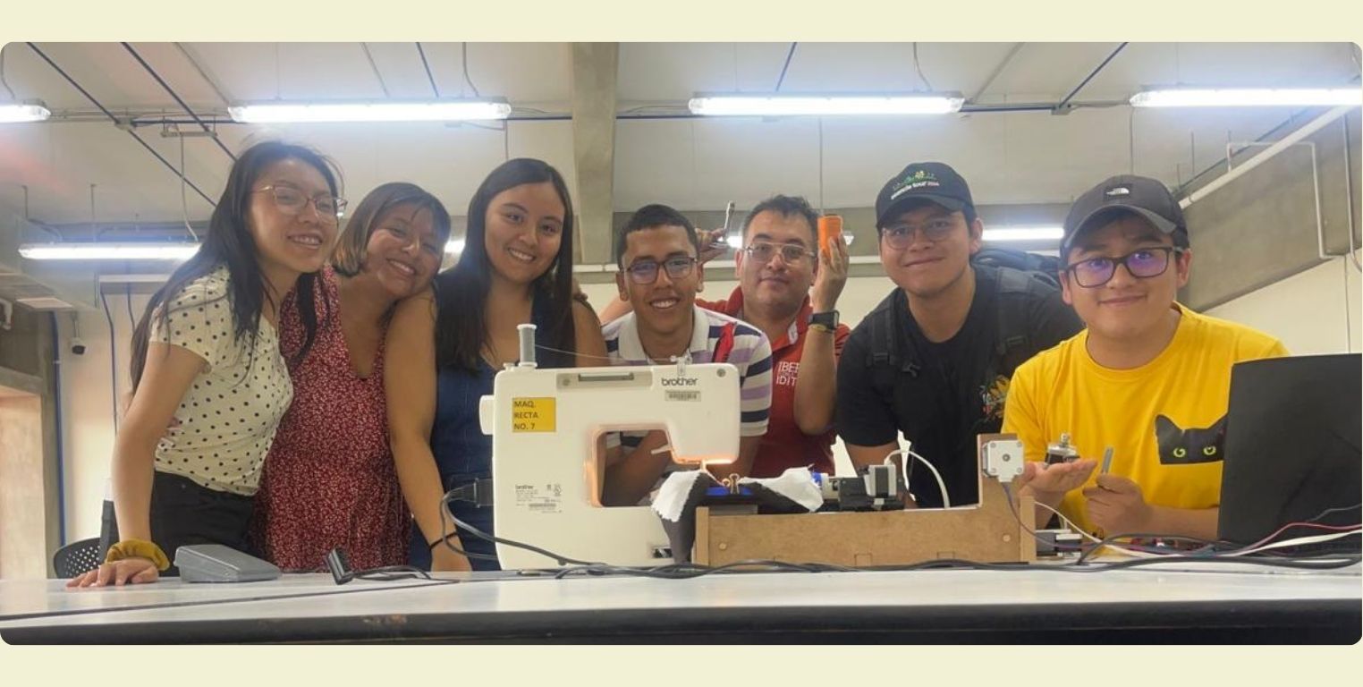
We dit it, it works!
Below, I'll share with you some photos of the machine and equipment (Olaf was missing from the photo). Plus videos showing that our machine actually works.
How could it be improved?
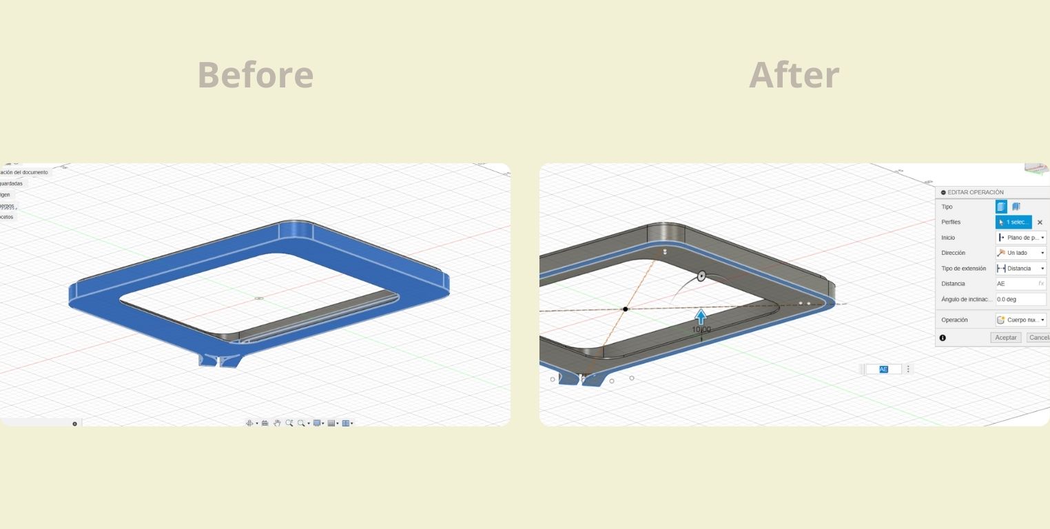
At the end of the tests, the machine kept moving, and it was detected that this was causing the fabric to loosen from the frame as well. So I added another adjustment system to the previous model.
- For this, what I did was to make a symmetry of this part of the sketch, first vertically, and then horizontally.
- In the end it is only an adjustment of the external part that is split in 2, because the internal part remains the same.
Conclusion
This is the first time I've worked with an interdisciplinary team, and although at the beginning I didn't feel so confident being the only designer surrounded by engineers, the truth is that we managed to work quite well, even despite the limited time and the uneven schedules we had to get together.
I also realized that I was able to learn how to work efficiently with them, and I'm sure there are many more things I can learn from them, but ultimately, as I put it on the machine sheet that I made for the group page, making it work is the most important thing. As a designer I must say that I am quite a perfectionist and I like to take care of every last detail of things. But sometimes the fact that it's done is better than perfect, even that helps you realize your mistakes faster and correct them anyway. Engineers have a particular way of thinking and doing things, and I will definitely seek to keep learning from them.
I appreciate the opportunity to learn from people in different areas of knowledge, and also to contribute with knowledge from my own. So thank you FabLab for this assignment outside of what we have been doing.
Files
- Embroidery hoop___STL
- Embroidery hoop___FUSION 360
- Improved version embroidery hoop___STL
- Improved version embroidery hoop___FUSION 360