Final Project
പൂമ്പാറ്റ: The Butterfly-Infinity Plotter
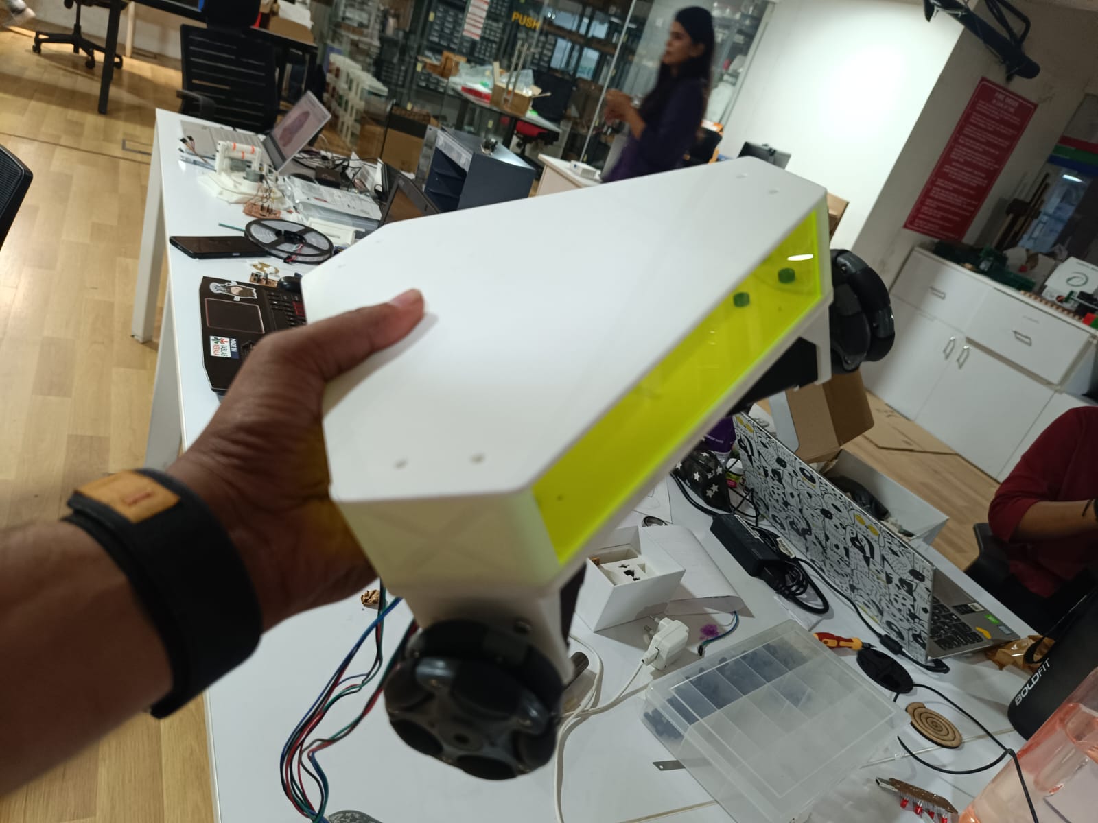
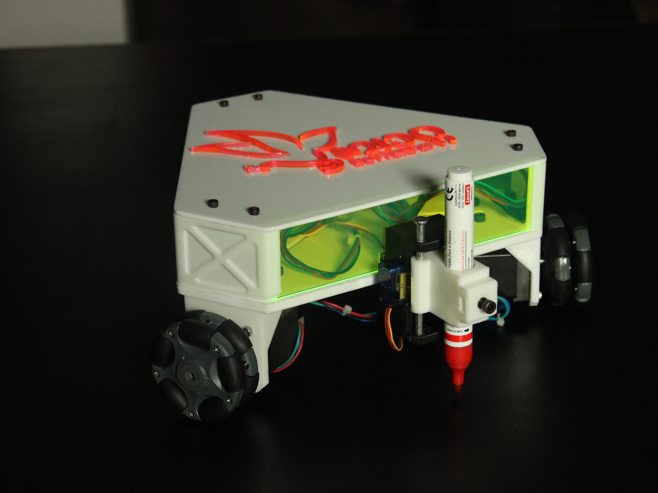
പൂമ്പാറ്റ:The Butterfly- Infinity Plotter is a compact and efficient XY plotter designed using three omni-wheels, stepper motors, an ESP32 microcontroller, and a Bluetooth module. The design aims to provide a precise, versatile, and cost-effective plotting solution for various applications.
The " പൂമ്പാറ്റ:The Butterfly- Infinity Plotter" is an innovative project that combines the precision of CNC technology with the creativity of artistry. This plotter is designed to draw intricate designs and images directly onto expansive canvases, such as walls and floors. With its CNC capabilities, it offers a high level of precision, allowing for the creation of detailed and captivating artworks on a larger scale. Whether transforming a blank wall into a vibrant mural or enhancing the aesthetics of a floor space, the Plotter opens up new possibilities for large-scale artistic expression. It's a fusion of technology and artistry, making it a unique and versatile tool for creative endeavors.
.png)
The Idea
Onam, the ten-day harvest festival of Kerala, is a dazzling display of culture, tradition, and joyous celebration. It's more than just a harvest festival; it's a homecoming, a renewal of spirit, and a time for families and communities to come together.
Onam is a vibrant and culturally rich festival celebrated predominantly in the Indian state of Kerala. It is an annual harvest festival that typically falls in the month of Chingam, the first month of the Malayalam calendar, which corresponds to August-September in the Gregorian calendar. Onam is celebrated
Pookalam: A Floral Welcome
Pookalam is a central part of Onam festivities. It's a floral design or rangoli made using a variety of colorful flowers and laid on the floor, particularly at the entrance of homes. These floral carpets are symbolic of prosperity and joy, and are believed to welcome King Mahabali, a mythical king who is said to visit Kerala during Onam.
The Making of a Pookalam
Traditionally, only locally available flowers were used to create pookalam. The preparation starts days before the main Onam day. Here's a glimpse into the process:
Each year, our office takes part in the tradition of drawing a pookalam for Onam. However, creating these intricate floral designs on the floor is a challenging and time-consuming process. It takes around 5-6 hours to draw the pattern.
This inspired the creation of "പൂമ്പാറ്റ: The Butterfly - Infinity Plotter," a cutting-edge tool designed to simplify and enhance this tradition.
"പൂമ്പാറ്റ: The Butterfly - Infinity Plotter" is a compact and efficient XY plotter, engineered with three omni-wheels, stepper motors, an ESP32 microcontroller, and a Bluetooth module. This innovative device merges the precision of CNC technology with the boundless creativity of artistic expression. The plotter's design ensures precise, versatile, and cost-effective plotting for a variety of applications.
This project embodies the fusion of technology and artistry, allowing for the creation of detailed and captivating designs directly onto expansive canvases such as walls and floors. The CNC capabilities of the plotter provide high precision, enabling the drawing of intricate and beautiful artworks on a larger scale. Whether transforming a blank wall into a vibrant mural or enhancing the aesthetics of a floor space, the "പൂമ്പാറ്റ: The Butterfly - Infinity Plotter" opens up new possibilities for large-scale artistic expression.
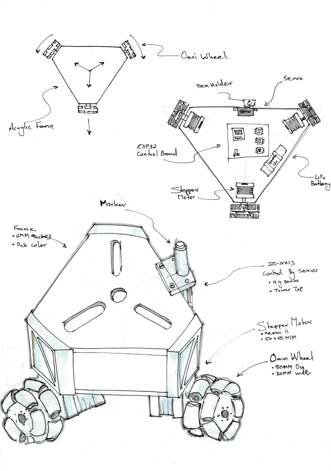
I have drawn a basic concept sketch in week 1
Project Management
For managing the final project, i have set a detailed project management plan
The project schedule outlines the steps from design and assembly to testing and final presentation.
Key Objectives of my project were outlined first
- Streamline the process of drawing pookalams.
- Achieve high precision and versatility in plotting designs.
- Ensure cost-effectiveness and ease of use.
- Enable large-scale artistic expression on floors.
Then I divided the project into various phases
Project Phases
1. Design Phase
- Main Body Design : Design the main body of the plotter.
- Motor Bracket Design : Design brackets to hold the motors.
- Wheel Coupling : Mill and prepare wheel couplings.
- Pen Holder Design : Design the holder for the plotting pen.
- PCB Design: Design the PCB in KiCAD
2. Manufacturing Phase
- Main Body Manufacturing : Manufacture the main body components using Zund and Laser Cutting Machine
- 3D Printing : Print the designed components using 3D printers.
- Milling : PCB Milling
3. Assembly Phase
- Assembly of Wheels : Assemble the omni-wheels.
- Assembly of Main Body : Assemble the main body components.
4. Electronics Phase
- Electronics Design Micro Controller Board : Design the microcontroller board.
- Electronics Design Main Board : Design the main electronics board.
- Electronics Production : Produce the designed electronic components.
- Soldering : Solder the electronic components.
5. Integration and Testing Phase
- Testing with CNC Shield : Test the assembly with a CNC shield.
- Software Checking and Interfacing : Ensure the software is correctly interfaced with the hardware.
- Testing Using Board : Conduct thorough testing using the electronics board.
- Total System Integration : Integrate all components and ensure system compatibility.
6. Documentation and Presentation Phase
- Documentation : Document the design, assembly, and testing processes.
- Final Presentation : Prepare and present the completed project.
Schedule Breakdown
| Date | Activity | Status | Remarks |
| 18 May 2024 | Main Body Design | Completed | Scheduled to Zund |
| 20 May 2024 | Motor Bracket Design | Completed | Scheduled to 3D printing |
| 21 May 2024 | Wheel Coupling | Completed | Done By Milling |
| 22 May 2024 | Assembly of Wheels | Completed | |
| 23 May 2024 | Assembly of Main Body | Completed | |
| 24 May 2024 | Testing with CNC Shield | Pending | |
| 27 May 2024 | Electronics Design Micro Controller Board | Pending | |
| 27 May 2024 | Electronics Design Main Board | Pending | |
| 28 May 2024 | Pen Holder Design | Pending | 3D Printing |
| 29 May 2024 | Electronics Production | Pending | |
| 30 May 2024 | Soldering | Pending | |
| 31 May 2024 | Soldering | Pending | |
| 1 June 2024 | Software Checking, Interfacing | Pending | |
| 2 June 2024 | Testing Using Board | Pending | |
| 3-5 June 2024 | Total System Integration | Pending | |
| 5-7 June 2024 | Documentation | Pending | |
| 10 June 2024 | Final Presentation | Pending |
Milestones set for the project
- Design Completion: All design-related activities completed by 28 May 2024.
- Manufacturing Completion: All manufacturing tasks completed by 23 May 2024.
- Assembly Completion: All assembly tasks completed by 23 May 2024.
- Electronics Completion: All electronics design and production completed by 31 May 2024.
- Testing Completion: All testing activities completed by 5 June 2024.
- Final Presentation: Final presentation prepared and delivered by 10 June 2024.
I have made KANBAN Board to visualize the progress
Design
First, i have to draw a concept sketch
this design was done in Fusion 360, on the second week as a part of the cad design this was just the concept inspired by an actual vehicle
System Integration
- Hardware Integration:
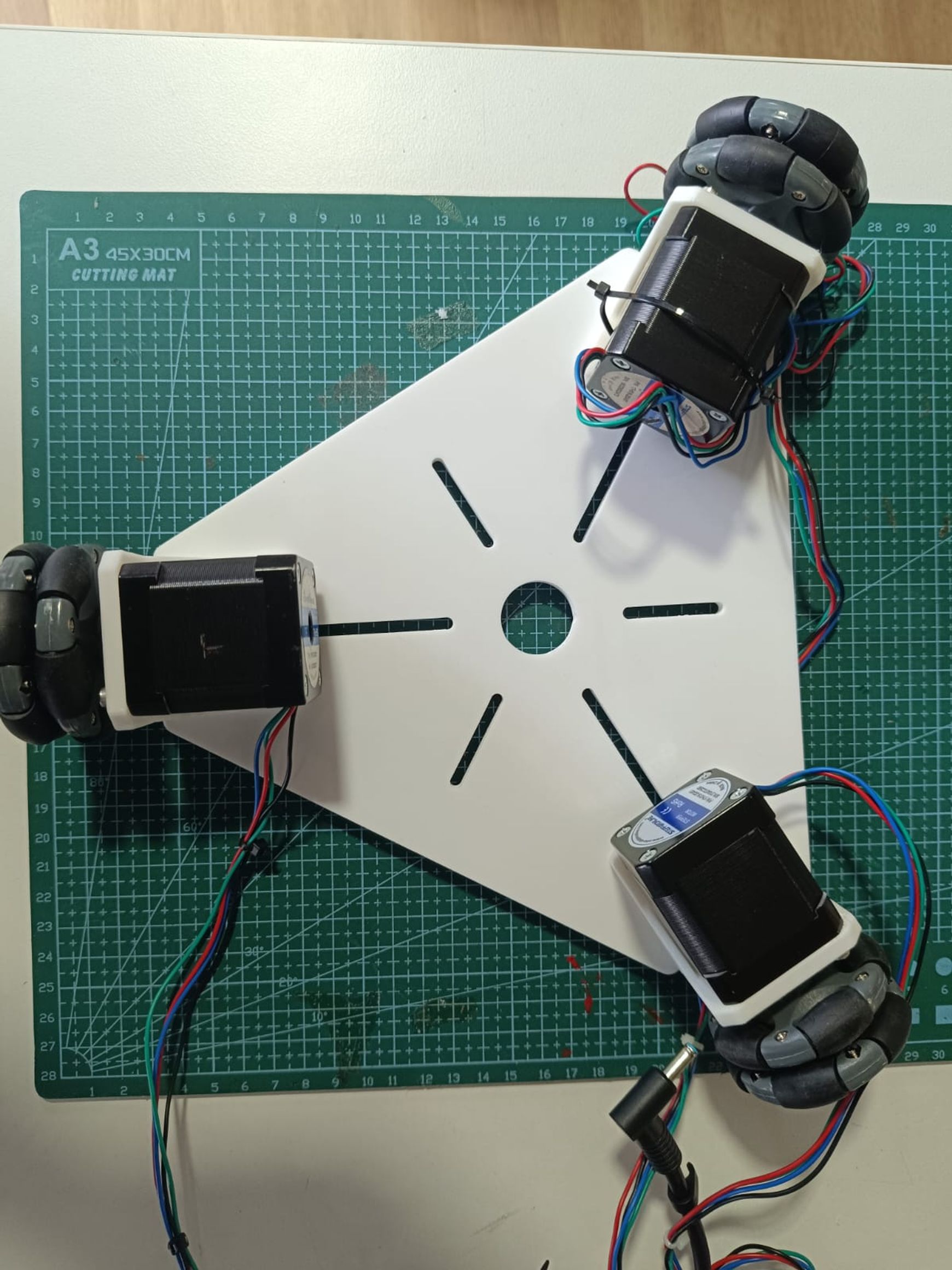
- Chassis and Motors:
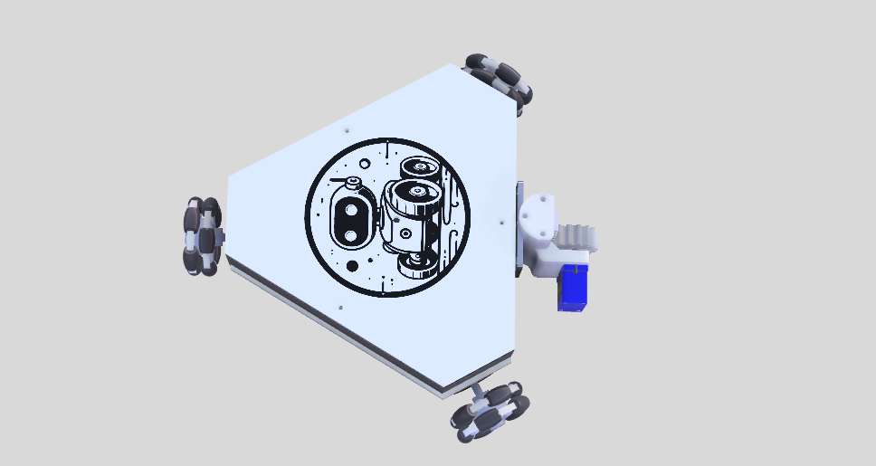
The plotter is built on a circular chassis made from Acrylic Sheet. Three NEMA 17 stepper motors are mounted using custom brackets. Each motor drives an omni-wheel, allowing for precise movement in any direction.
- Microcontroller and Driver Boards:
An ESP 32 is used to control the plotter, interfacing with three motor Driver boards (one for each stepper motor). The driver boards manage the current supplied to the motors, ensuring smooth and precise motion.
.jpg)
- Power Supply:
The system is powered by a 12V power supply. Voltage regulation is handled by the driver boards and the Arduino’s onboard regulator to ensure the components receive the appropriate voltage and current.
- Chassis and Motors:
- Software Integration:
- G-Code Interpreter:
The plotter features an onboard interpreter that recognizes G-code commands generated by software like Inkscape. This allows for easy conversion of designs into plotting instructions.
.png)
- Bluetooth Communication:
AnESP 32 module allows the plotter to receive commands wirelessly from a PC or a mobile device. This provides flexibility in controlling the plotter remotely.
- Control Software:
This software is used to send G-code files to the plotter, enabling it to execute complex drawing tasks.
- G-Code Interpreter:
- Mechanical Design:
- Omni-Wheels and Motion:
The three omni-wheels are crucial for the plotter’s movement, providing traction only in the direction of rotation. This unique design allows for smooth and precise movement in any direction on the plotting surface.

Omni wheels only have traction in the direction of rotation.
If three omni-wheels are arranged as shown in image then vertical upward motion is possible if
- wheel W1 does not rotate,
- wheel W2 rotates counter-clockwise, and
- wheel W3 rotates in a clock-wise direction.
Horizontal motion to the right is possible if
- wheel W1 rotates counter-clockwise and
- wheels W2 and W3 both rotate in a clock-wise direction
The direction of travel may be changed by reversing the wheel rotations.
“Bresenham’s Line Drawing Algorithm. which only requires horizontal and vertical motion, is used to draw curves, circles, and diagonal lines.
The required wheel speeds for horizontal and vertical motion are summarized below:
- for horizontal motion, wheel W1 must rotate twice as fast as wheels W2 and W3.
- for vertical motion, since wheels W2 and W3 are angled, the image must be scaled sqrt(3) vertically if a square is to look like a square when plotted.
- Pen Mechanism:
An SG90 servo motor is used to control the pen mechanism, lifting and lowering the pen as needed to draw on the surface.
- Omni-Wheels and Motion:
Features of the Machine
- Compact Design:
The plotter has a small footprint, making it suitable for use in limited spaces.
- Large Drawing Area:
Despite its compact size, the plotter can handle large drawings due to its Bluetooth design, which eliminates the need for physical connections that restrict movement.
- High Resolution:
The plotter achieves a horizontal resolution of 8.78 steps per mm, ensuring precise and detailed drawings.
- Bluetooth Operation:
The wireless design allows for remote control and operation, increasing convenience and flexibility.
- Simple Construction:
The design minimizes metalwork and only requires basic tools for assembly, making it accessible for hobbyists and DIY enthusiasts.
Design Parameters
- Plotting Area: The effective plotting area is determined by the movement range of the omni-wheels and the length of the pen mechanism. The design should accommodate various paper sizes typically used for plotting.
- Stepper Motor Specifications: The NEMA 17 stepper motors are chosen for their balance of torque and precision. The current and voltage settings are adjusted using the Big Easy Driver boards to match the motor specifications.
- Servo Motor Range: The SG90 servo motor's range of motion is calibrated to ensure the pen can be lifted and lowered accurately without causing smudges or missed lines.
- Power Supply Requirements: The 12V power supply should provide sufficient current to power all three stepper motors and the servo motor simultaneously, with consideration for peak power demands during operation.
I have re modified the design which i had drawn in week 2
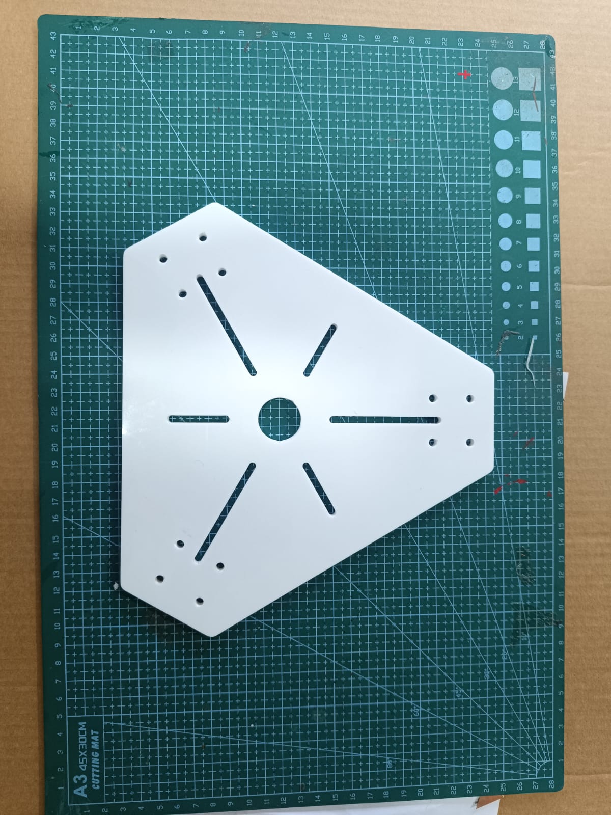
Then i started converting the concept Sketch to Fusion , Started Drawing the baase frame
.png)
Then i have to draw the sketch for mounts
.png)
Later, I have exported the NEMA 17 and
.png)
Add side features
.png)
.png)
.png)
.png)
Draw the pen lift Mechanism using servo
.png)
.png)
Electronics Design
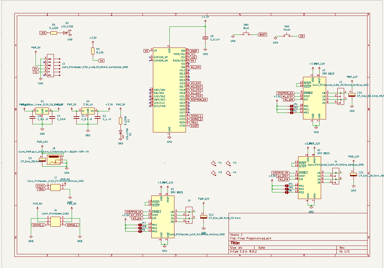
The plotter is driven by three NEMA 17 stepper motors, each controlled by a DRV8825 motor driver. The system is powered by a 12V supply, with the control logic managed by an ESP32 microcontroller. The following sections detail the components and their interconnections within the schematic.
Components and Connections
- Microcontroller (ESP32)
The ESP32 microcontroller serves as the brain of the plotter. It interfaces with the motor drivers and controls the stepper motors' movements. The ESP32 is powered by a 3.3V supply and uses various GPIO pins for motor control signals (STEP, DIR, and ENABLE) for each motor driver.
- Power Supply
The power supply section includes a 12V input that is regulated down to 5V and 3.3V using voltage regulators. The 12V supply powers the DRV8825 motor drivers, while the 3.3V supply powers the ESP32 and other logic components. Decoupling capacitors are placed near power supply pins to filter out noise and ensure stable operation.
- Motor Drivers (DRV8825)
Three DRV8825 stepper motor drivers control the NEMA 17 motors.
- Connectors and Headers
Multiple connectors and headers are used for interfacing with external components, including power inputs, motor connections, and additional peripherals. Headers are also provided for programming and debugging purposes.
- LEDs and Indicators
LEDs with current-limiting resistors are included in the design to indicate the status of various signals and power lines. These LEDs help in troubleshooting and ensure that the system is functioning correctly.
- Capacitors and Resistors
Decoupling capacitors are strategically placed near power supply pins to reduce noise. Pull-up and pull-down resistors are used where necessary to maintain stable logic levels on the control signals.
For motor W1, configure the DRV8825 for 8x micro-stepping by setting M0 and M1 to HIGH and M2 to LOW. For motors W2 and W3, set the DRV8825 to 16x micro-stepping by connecting M0, M1, and M2 to HIGH. The DRV8825 can accept an input voltage in the range of 8-45 volts, so use an 8-volt power supply for day-to-day use to minimize heat dissipation, and consider a LiPo battery for self-contained operation, as the current drain can approach 2A. Adjust each motor current to 600mA (0.6 amps) using the “current limit” potentiometers on the DRV8825 modules. To do this, turn off power to the driver, measure the VREF voltage with a multimeter, and adjust the potentiometer until VREF is 0.3V. Turn the power back on and verify the setting.
Then i moved on to tracing the paths
.png)
I generated the drill files and plot files from Kicad and used https://gerber2png.fablabkerala.in/ for generating png outputs for production.
.png)
.png)
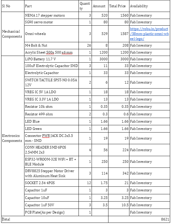
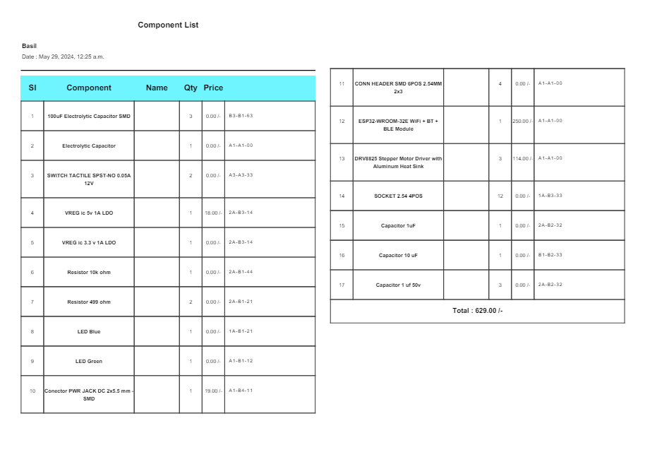
BoM
After the design, I prepared the Bill of Materials and ordered the Omni wheels from Robu.in rest of the components were blocked in inventory.
Manufacturing
Body
In week15 i was used to cut my project main body in Zund . Refer the documentation of week15 for more details.
.png)
Motor Mounts
The motor mount is designed for NEMA 17 it can be directly mount on the body using M4 Bolts
%201.png)
Added to Prusa MK3+
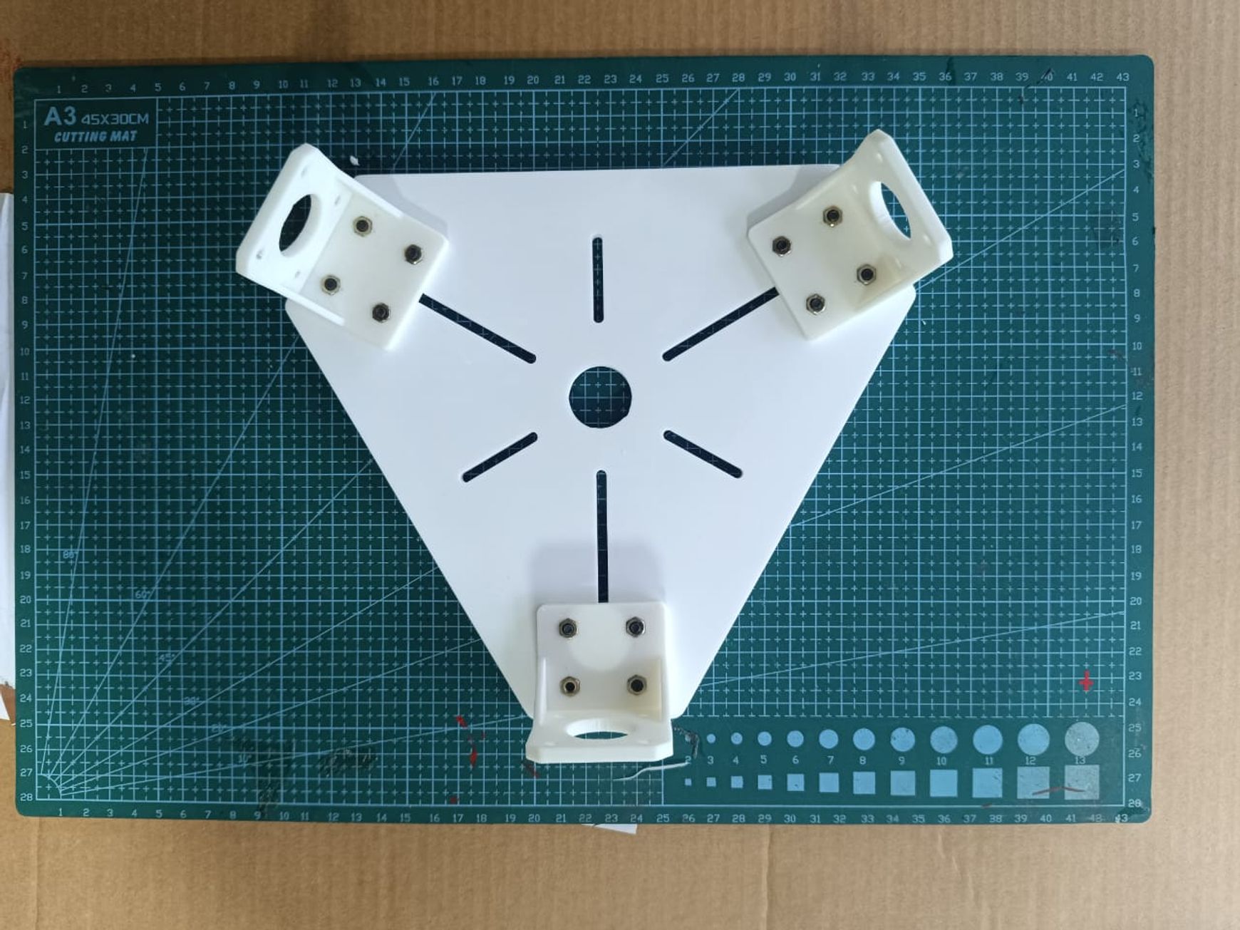
Then i sourced the NEMA17 from FAB inventory and connected in motor Mounts
Top & Side Covers
I have used Laser cutting Machine in my FABLAB to cut logo and , side & top panels
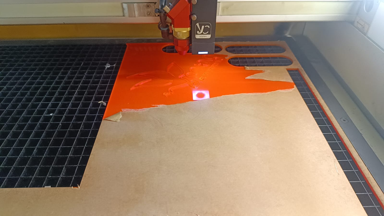
Since i was already familier with CNC Week refer my documentation
Just for curiosity, I just assembled and checked the final look
Then I have pasted the logo of my project carefully
Pen Lift
I have already designed the penlift mechanism using sevo motor
%201.png)
I have 3D printed the parts for the pen lift mechanism
Electronics Production
So once i have completed the electronics design, i have scheduled the electronics production for the next day. So I have already become familiar with CNC milling of the PCB boards (refer to my documentation from Week 4 but I am super excited to produce the double-sided PCB .
Trace Path
.png)
Drill Paths

First, i traced the path of top layer
after tracing the top layer and drill holes i take out the pcb for next side milling
Paste the double side tape for bottom layer tracing
Placed the PCB properly on bottomside
then traced and cut the outer line
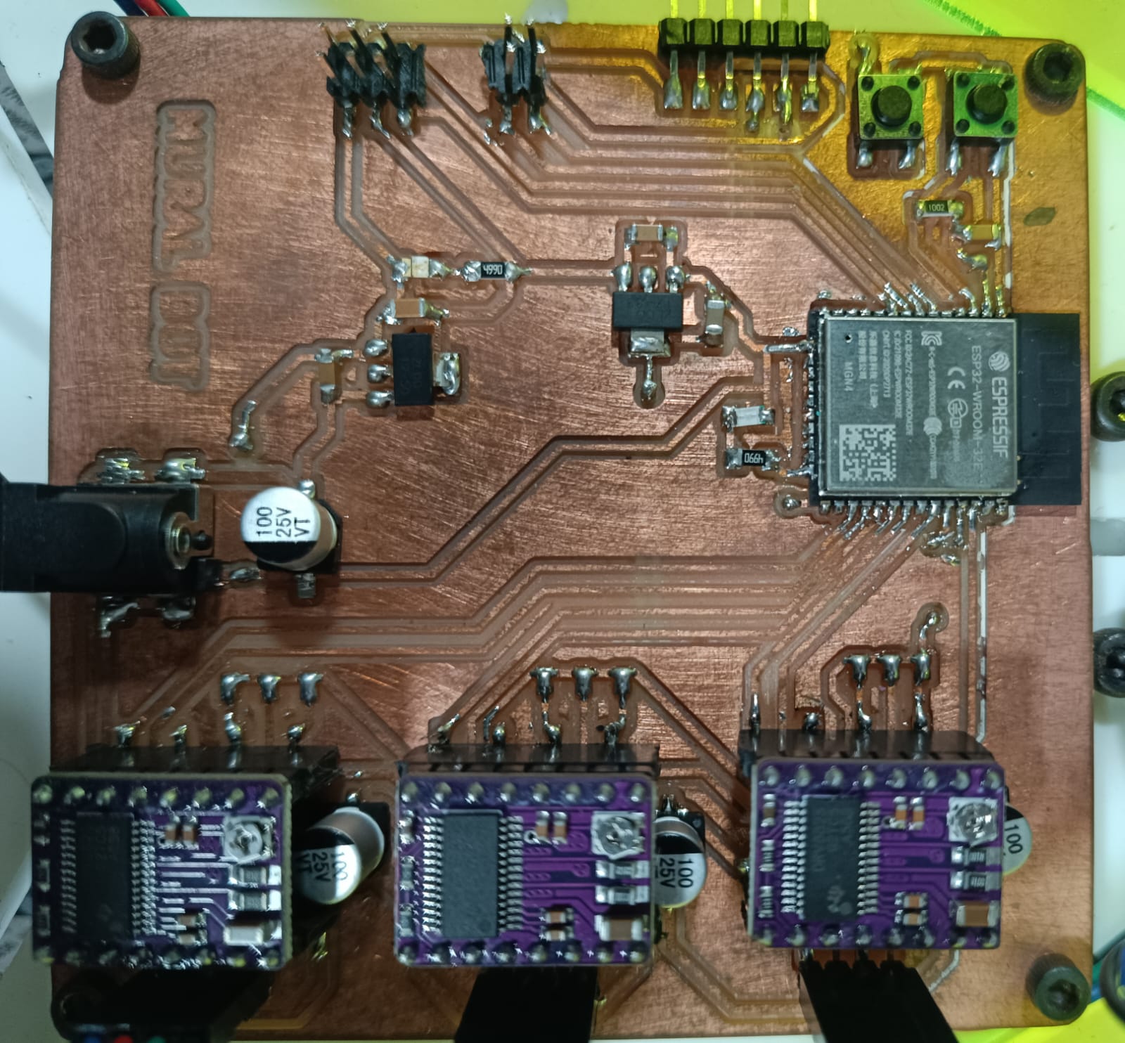
Finally i got my double Side PCB
.jpeg)
Soldering
For soldering, i have sourced the components from Fab Inventory
.jpeg)
After 4 hrs………
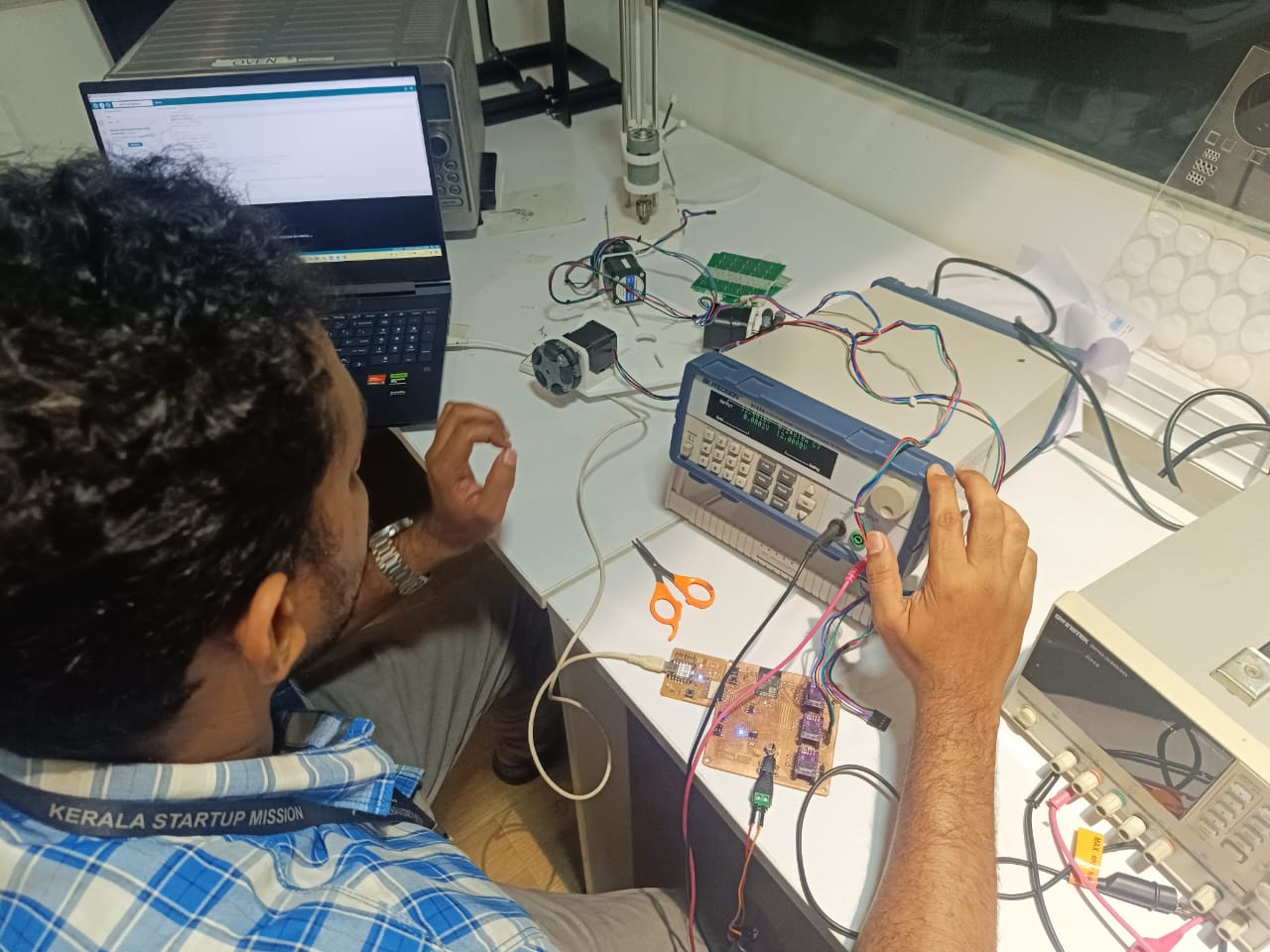
Testing the Board
Once i completed the soldering , ineed to test the PCB for its functionality ,
I screwed in two wires at the terminal and connected it to DC Power Supply.
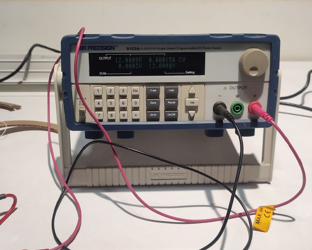
Parameter values set on DC Power Supply
            Voltage: 12V
            Current: 0.6A
Current Limiting Potentiometer
Before running the motor, we must limit the maximum current flowing through the stepper coils so that it does not exceed the motor’s rated current. This is done by tightenening or loosening the screw which actually is a current-limiting potentiometer. Here, I have set its voltage at around 0.6V.
Refer Last Minute Engineers to know about the two methods in which the adjustment can be done.
i have given the program for testing
// defines pins
          #define stepPin 10
          #define dirPin 0
          #define faultPin 8
          #define enablePin 9

          void setup() {
            // Sets the pins as Outputs
            pinMode(stepPin,OUTPUT);
            pinMode(dirPin,OUTPUT);
            pinMode(faultPin,OUTPUT);
            pinMode(enablePin,OUTPUT);
          }
          void loop() {
            digitalWrite(dirPin,HIGH); // Enables the motor to move in a particular direction
            digitalWrite(enablePin,LOW); // DRV8825 driver is enabled when the pin is LOW
             digitalWrite(faultPin,HIGH); // If FAULT pin is LOW, chip is disabled
            // Makes 200 pulses for making one full cycle rotation
            for(int x = 0; x < 800; x++) {
              digitalWrite(stepPin,HIGH);
              delayMicroseconds(700);    // by changing this time delay between the steps we can change the rotation speed
              digitalWrite(stepPin,LOW);
              delayMicroseconds(700);
            }
            delay(1000); // One second delay

            digitalWrite(dirPin,LOW); //Changes the rotations direction
            // Makes 400 pulses for making two full cycle rotation
            for(int x = 0; x < 1600; x++) {
              digitalWrite(stepPin,HIGH);
              delayMicroseconds(500);
              digitalWrite(stepPin,LOW);
              delayMicroseconds(500);
            }
            delay(1000);
          }
Testing video
I have also checked the penlift mechanism by servo example code in Arduiuo IDE
#include <Servo.h>

          Servo myservo;  // create servo object to control a servo
          // twelve servo objects can be created on most boards

          int pos = 0;    // variable to store the servo position

          void setup() {
            myservo.attach(32);
          }

          void loop() {
            for (pos = 0; pos <= 180; pos += 1) { // goes from 0 degrees to 180 degrees
              // in steps of 1 degree
              myservo.write(pos);              // tell servo to go to position in variable 'pos'
              delay(15);                       // waits 15 ms for the servo to reach the position
            }
            for (pos = 180; pos >= 0; pos -= 1) { // goes from 180 degrees to 0 degrees
              myservo.write(pos);              // tell servo to go to position in variable 'pos'
              delay(15);                       // waits 15 ms for the servo to reach the position
            }
          }
Testing Video
It was smoothly functioned
Assembly
So far, I have only assembled the body and omni-wheels after manufacturing, so by the time I got to the final assembly, I was quite experienced. For the final assembly, I used drill drivers and screwdrivers.You can see the partialassembled images above
Here is the detailed video
final assembled picture
Now its time to programming the board
Programming
For omni wheel mechanism I have referenced the internet for the movement mechanism- Read full article here
Abstract of the mechanism is given below
Horizontal motion
For horizontal motion to the right:
- whee1 W1 must rotate counter clock-wise (CCW)
- wheels W2 and W3 both rotate clock-wise (CW).
- Wheel W1 must rotate twice as fast as wheels W2 and W3.
A wheel speed ratio of exactly 2 is possible using 16x and 8x micro-stepping.
A NEMA 17 motor with a 58mm diameter wheel (W1) and 8x micro-stepping equates to a horizontal resolution of 0.114mm per step or 8.78 steps per mm.
Vertical motion
For upward vertical motion:
- wheel W1 does not rotate.
- wheel W2 must rotate CCW
- wheel W3 must rotate CW
- wheels W2 and W3 must both rotate 1/sqrt(3)=0.5774 times for 1 unit of travel.
A wheel speed of 0.5774 is NOT possible using stepping motors ... a simple solution is to multiply all vertical dimensions by sqrt(3).
So based on this, my instructer Saheen helped me to reach to the full programme
We have used Platform.io for smoother compiling
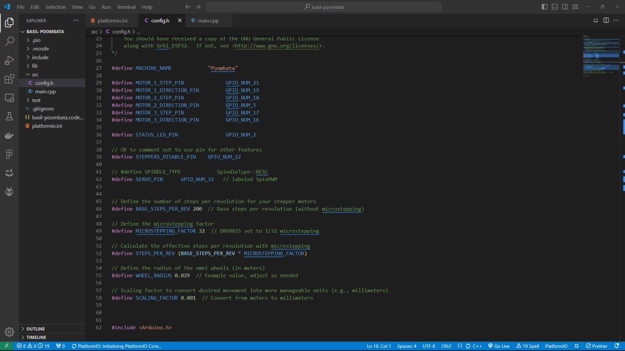
#include <config.h>
#include <ESP32Servo.h>
#include <AccelStepper.h>
#include <MultiStepper.h>
#include <string.h>
#include "BluetoothSerial.h"
#define DEBUG
// DEFINE GRBL SERIAL PORT
BluetoothSerial SerialBT;
// DEFINE STEPPER PINS
AccelStepper stepper1(AccelStepper::DRIVER, MOTOR_1_STEP_PIN, MOTOR_1_DIRECTION_PIN);
AccelStepper stepper2(AccelStepper::DRIVER, MOTOR_2_STEP_PIN, MOTOR_2_DIRECTION_PIN);
AccelStepper stepper3(AccelStepper::DRIVER, MOTOR_3_STEP_PIN, MOTOR_3_DIRECTION_PIN);
MultiStepper steppers;
// initializing servo
Servo penServo;
#define MOTOR_1_MAX_SPEED 3000
#define MOTOR_2_MAX_SPEED 3000
#define MOTOR_3_MAX_SPEED 3000
#define MOTOR_1_MAX_ACCELERATION 1000
#define MOTOR_2_MAX_ACCELERATION 1000
#define MOTOR_3_MAX_ACCELERATION 1000
#define LINE_BUFFER_LENGTH 1024
#define STEPPERS_DISABLED 1
#define STEPPERS_ENABLED 0
struct point
{
float x;
float y;
float z;
int speed;
};
struct point actuatorPos;
float StepInc = 1;
int StepDelay = 0;
int LineDelay = 50;
// float StepsPerMillimeterX = 0.86;
// float StepsPerMillimeterY = 0.5;
float StepsPerMillimeterX = 86.0;
float StepsPerMillimeterY = 50.0;
float Xmin = 0;
float Ymin = 0;
float Xpos = Xmin;
float Ypos = Ymin;
boolean verbose = false;
long positions[2];
float xPosition = 0.0;
float yPosition = 0.0;
void mov(long x, long y)
{
// Convert desired position changes to scaled velocities
float Vx = x * SCALING_FACTOR;
float Vy = y * SCALING_FACTOR;
// float Vz = z * SCALING_FACTOR;
// Initialize velocities
float v1 = 0;
float v2 = 0;
float v3 = 0;
// Calculate wheel velocities for X direction (forward/backward)
if (Vx != 0)
{
v2 = Vx / WHEEL_RADIUS;
v3 = -Vx / WHEEL_RADIUS;
}
// Calculate wheel velocities for Y direction (sideways)
if (Vy != 0)
{
v1 = 2 * Vy / WHEEL_RADIUS;
v2 = Vy / WHEEL_RADIUS;
v3 = Vy / WHEEL_RADIUS;
}
// Convert velocities to steps (using a time interval of 1 second for simplicity)
positions[0] = v1 * STEPS_PER_REV / (2 * PI);
positions[1] = v2 * STEPS_PER_REV / (2 * PI);
positions[2] = v3 * STEPS_PER_REV / (2 * PI);
steppers.moveTo(positions);
steppers.runSpeedToPosition();
stepper1.setCurrentPosition(0);
stepper2.setCurrentPosition(0);
stepper3.setCurrentPosition(0);
}
// void drawLine(float x1, float y1)
// {
// float dx = x1 - xPosition;
// float dy = y1 - yPosition;
// #ifdef DEBUG
// // Debugging output for target positions
// Serial.print("Target X: ");
// Serial.println(x1);
// Serial.print("Target Y: ");
// Serial.println(y1);
// // Debugging output for relative movements
// Serial.print("Move X by: ");
// Serial.println(dx);
// Serial.print("Move Y by: ");
// Serial.println(dy);
// #endif
// // Update current positions based on movement
// xPosition = x1;
// yPosition = y1;
// #ifdef DEBUG
// // Debugging output for new positions
// Serial.print("xPosition: ");
// Serial.println(xPosition);
// Serial.print("yPosition: ");
// Serial.println(yPosition);
// #endif
// mov(dx, dy); // Call the actual move function with relative distances
// }
void drawLine(float x1, float y1) {
if (verbose)
{
Serial.print("fx1, fy1: ");
Serial.print(x1);
Serial.print(",");
Serial.print(y1);
Serial.println("");
}
if (verbose)
{
Serial.print("Xpos, Ypos: ");
Serial.print(Xpos);
Serial.print(",");
Serial.print(Ypos);
Serial.println("");
}
if (verbose)
{
Serial.print("x1, y1: ");
Serial.print(x1);
Serial.print(",");
Serial.print(y1);
Serial.println("");
}
// Convert coordinates to steps
x1 = (int)(x1*StepsPerMillimeterX);
y1 = (int)(y1*StepsPerMillimeterY);
float x0 = Xpos;
float y0 = Ypos;
// Let's find out the change for the coordinates
long dx = abs(x1-x0);
long dy = abs(y1-y0);
int sx = x0<x1 ? StepInc : -StepInc;
int sy = y0<y1 ? StepInc : -StepInc;
long i;
long over = 0;
if (dx > dy) {
for (i=0; i<dx; ++i) {
// myStepperX.step(sx);
mov(sx, 0);
over+=dy;
if (over>=dx) {
over-=dx;
// myStepperY.step(sy);
mov(0, sy);
}
delay(StepDelay);
}
}
else {
for (i=0; i<dy; ++i) {
// myStepperY.step(sy);
mov(0, sy);
over+=dx;
if (over>=dy) {
over-=dy;
// myStepperX.step(sx);
mov(sx, 0);
}
delay(StepDelay);
}
}
if (verbose)
{
Serial.print("dx, dy:");
Serial.print(dx);
Serial.print(",");
Serial.print(dy);
Serial.println("");
}
if (verbose)
{
Serial.print("Going to (");
Serial.print(x0);
Serial.print(",");
Serial.print(y0);
Serial.println(")");
}
delay(LineDelay);
Xpos = x1;
Ypos = y1;
}
void processIncomingLine(char *line, int charNB)
{
int currentIndex = 0;
char buffer[64];
struct point newPos;
newPos.x = 0.0;
newPos.y = 0.0;
newPos.z = 0.0;
newPos.speed = 0;
int G_command = 0;
char *indexX;
char *indexY;
char *indexZ;
char *indexSpeed;
while (currentIndex < charNB)
{
switch (line[currentIndex++])
{
case 'G':
buffer[0] = line[currentIndex++];
buffer[1] = line[currentIndex++];
buffer[2] = '\0';
G_command = atoi(buffer);
switch (atoi(buffer))
{
case 00:
// Serial.println(atoi(buffer));
case 01:
// Serial.println("G01");
Serial.println('Function :: ');
indexX = strchr(line + currentIndex++, 'X');
indexY = strchr(line + currentIndex++, 'Y');
indexZ = strchr(line + currentIndex++, 'Z');
indexSpeed = strchr(line + currentIndex++, 'F');
if (indexSpeed > 0)
{
newPos.speed = atof(indexSpeed + 1);
}
if (G_command == 1)
{
Serial.print("Speed :: ");
Serial.println(newPos.speed);
stepper1.setMaxSpeed(newPos.speed);
stepper2.setMaxSpeed(newPos.speed);
stepper3.setMaxSpeed((newPos.speed) / 2);
}
else if (G_command == 0)
{
stepper1.setMaxSpeed(MOTOR_1_MAX_SPEED);
stepper2.setMaxSpeed(MOTOR_2_MAX_SPEED);
stepper3.setMaxSpeed(MOTOR_3_MAX_SPEED);
}
if (indexY <= 0 && indexZ <= 0)
{ // If Y and Z are missing
newPos.y = actuatorPos.y;
newPos.z = actuatorPos.z;
newPos.x = atof(indexX + 1);
}
else if (indexX <= 0 && indexZ <= 0)
{ // If X and Z are missing
newPos.x = actuatorPos.x;
newPos.z = actuatorPos.z;
newPos.y = atof(indexY + 1);
}
else if (indexX <= 0 && indexY <= 0)
{ // If X and Y are missing
newPos.x = actuatorPos.x;
newPos.y = actuatorPos.y;
newPos.z = atof(indexZ + 1);
}
else if (indexZ <= 0)
{ // If Z is missing
newPos.x = atof(indexX + 1);
newPos.y = atof(indexY + 1);
newPos.z = actuatorPos.z;
}
else if (indexY <= 0)
{ // If Y is missing
newPos.x = atof(indexX + 1);
newPos.z = atof(indexZ + 1);
newPos.y = actuatorPos.y;
}
else if (indexX <= 0)
{ // If X is missing
newPos.y = atof(indexY + 1);
newPos.z = atof(indexZ + 1);
newPos.x = actuatorPos.x;
}
else
{ // All coordinates are present
newPos.x = atof(indexX + 1);
newPos.y = atof(indexY + 1);
newPos.z = atof(indexZ + 1);
}
drawLine(newPos.x, newPos.y);
actuatorPos.x = newPos.x;
actuatorPos.y = newPos.y;
actuatorPos.z = newPos.z;
break;
case 28:
Ypos = 0.0;
Xpos = 0.0;
xPosition = 0.0;
yPosition = 0.0;
SerialBT.println("Home Position Set X = 0.0 Y = 0.0");
// home();
break;
default:
SerialBT.println("Unknown command");
break;
}
break;
case 'M':
buffer[0] = line[currentIndex++];
buffer[1] = line[currentIndex++];
buffer[2] = '\0';
switch (atoi(buffer))
{
case 03:
{
char *indexS = strchr(line + currentIndex++, 'S');
int servoAngle = atoi(indexS + 1);
if (servoAngle <= 180 && servoAngle >= 0)
{
penServo.write(servoAngle);
delay(15);
#ifdef DEBUG
Serial.println(servoAngle);
#endif
}
}
break;
default:
SerialBT.print("Command not recognized : M");
SerialBT.println(buffer);
break;
}
break;
default:
SerialBT.print("Unknown command : ");
SerialBT.println(buffer);
break;
}
}
}
void processCommands()
{
delay(200);
char line[LINE_BUFFER_LENGTH];
char c;
int lineIndex;
bool lineIsComment, lineSemiColon;
lineIndex = 0;
lineSemiColon = false;
lineIsComment = false;
while (1)
{
while (SerialBT.available() > 0)
{
c = SerialBT.read();
if ((c == '\n') || (c == '\r'))
{
if (lineIndex > 0)
{
line[lineIndex] = '\0';
if (verbose)
{
SerialBT.print("Received : ");
SerialBT.println(line);
}
if (strcmp(line, "G28") == 0)
{
// home();
Xpos = 0.0;
Ypos = 0.0;
xPosition = 0.0;
yPosition = 0.0;
SerialBT.println("Home Position Set X = 0.0 Y = 0.0");
}
else
{
processIncomingLine(line, lineIndex);
}
lineIndex = 0;
}
else
{
}
lineIsComment = false;
lineSemiColon = false;
SerialBT.println("OK");
}
else
{
if ((lineIsComment) || (lineSemiColon))
{
if (c == ')')
lineIsComment = false;
}
else
{
if (c <= ' ')
{
}
else if (c == '/')
{
}
else if (c == '(')
{
lineIsComment = true;
}
else if (c == ';')
{
lineSemiColon = true;
}
else if (lineIndex >= LINE_BUFFER_LENGTH - 1)
{
Serial.println("ERROR - lineBuffer overflow");
lineIsComment = false;
lineSemiColon = false;
}
else if (c >= 'a' && c <= 'z')
{
line[lineIndex++] = c - 'a' + 'A';
}
else
{
line[lineIndex++] = c;
}
}
}
}
}
}
void setup()
{
Serial.begin(115200);
SerialBT.begin(MACHINE_NAME);
pinMode(STEPPERS_DISABLE_PIN, OUTPUT);
pinMode(STATUS_LED_PIN, OUTPUT);
penServo.attach(SERVO_PIN);
delay(15); // wait for 15 ms
penServo.write(50);
delay(15); // wait for 15 ms
// Configure each stepper
stepper1.setMaxSpeed(MOTOR_1_MAX_SPEED);
stepper1.setAcceleration(MOTOR_1_MAX_ACCELERATION);
stepper1.setCurrentPosition(0);
stepper2.setMaxSpeed(MOTOR_2_MAX_SPEED);
stepper2.setAcceleration(MOTOR_2_MAX_ACCELERATION);
stepper2.setCurrentPosition(0);
stepper3.setMaxSpeed(MOTOR_3_MAX_SPEED);
stepper3.setAcceleration(MOTOR_3_MAX_ACCELERATION);
stepper3.setCurrentPosition(0);
steppers.addStepper(stepper1);
steppers.addStepper(stepper2);
steppers.addStepper(stepper3);
Serial.println(" Poombata is Ready pair with bluetooth");
// Serial.print("X range is from ");
// Serial.print(Xmin);
// Serial.print(" to ");
// Serial.print(Xmax);
// Serial.println(" mm.");
// Serial.print("Y range is from ");
// Serial.print(Ymin);
// Serial.print(" to ");
// Serial.print(Ymax);
// Serial.println(" mm.");
// Serial.print("Z range is from ");
// Serial.print(Zmin);
// Serial.print(" to ");
// Serial.print(Zmax);
// Serial.println(" mm.");
digitalWrite(STEPPERS_DISABLE_PIN, STEPPERS_ENABLED);
}
void loop()
{
processCommands();
}It uses bluetooth communication with the board using webserial .
Testing of the code with Board
So once the program is sent to the board, we test the movements
Horzontal and vertical Movements
Circular Interpolation
Infinity Plotter Interface
The Infinity Plotter is a Frontend Application, developed using the Next.js framework. The application facilitates seamless communication with connected CNC (Computer Numerical Control) machines through the WebSerial API. This interface aims to offer a user-friendly experience for monitoring and controlling CNC operations directly from a web browser.
Our developer, Midhlaj helped me to build this.
%201.png)
Real-time Communication
Enables direct and efficient communication with CNC machines using the WebSerial API.
User-friendly Interface
Designed with a clean and intuitive interface to ensure ease of use for operators.
Cross-Platform Accessibility
Being a web application, it can be accessed from any device with a web browser, providing flexibility and convenience.
Next.js Framework
Utilizes the powerful features of Next.js, including server-side rendering and static site generation, to ensure optimal performance and SEO.
Technical Details
Framework
The frontend application is built using the Next.js framework. Next.js is a popular React framework that offers several benefits, including:
- Server-Side Rendering (SSR): Improves performance by rendering pages on the server.
- Static Site Generation (SSG): Allows pre-rendering of pages at build time, which enhances load times and SEO.
- API Routes: Simplifies the creation of backend APIs within the same project.
WebSerial API
The WebSerial API is a modern browser API that provides direct access to serial ports. This is crucial for enabling real-time communication between the web application and CNC machines. Key capabilities include:
- Port Access: Open and close connections to serial ports.
- Data Transfer: Send and receive data to/from the CNC machine.
- Event Handling: Handle serial port events to manage data streams and connection states.
Communication Workflow
- Port Connection: The user selects the appropriate serial port connected to the CNC machine.
- Data Exchange: The application sends commands to and receives responses from the CNC machine via the WebSerial API.
- Real-time Monitoring: The interface updates in real-time based on the data received from the CNC machine, allowing users to monitor operations seamlessly.
FInal Result
So my work is almost complete, and tested various patterns by the G Code sender
Here is some videos
It is drawing infinite planes
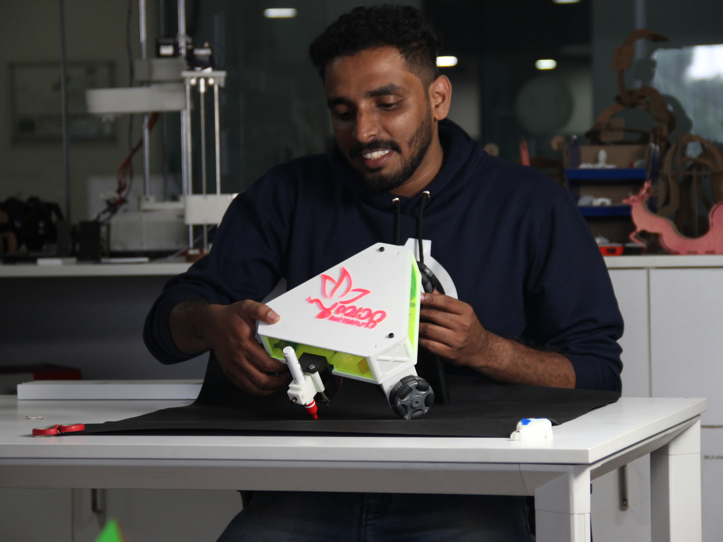
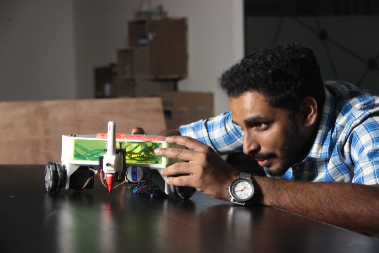
me with my പൂമ്പാറ്റ……
Final Video
Downloads