Electronics Production
Tasks for this week
Individual assignment:
- make and test a microcontroller development board
group assignment:
- characterize the design rules for your in-house PCB production process
- send a PCB out to a board house
Group Assignment
The Week 4 Group Assignment is to characterize the design rules for the in-house PCB production process and also to send a PCB out to a board house.
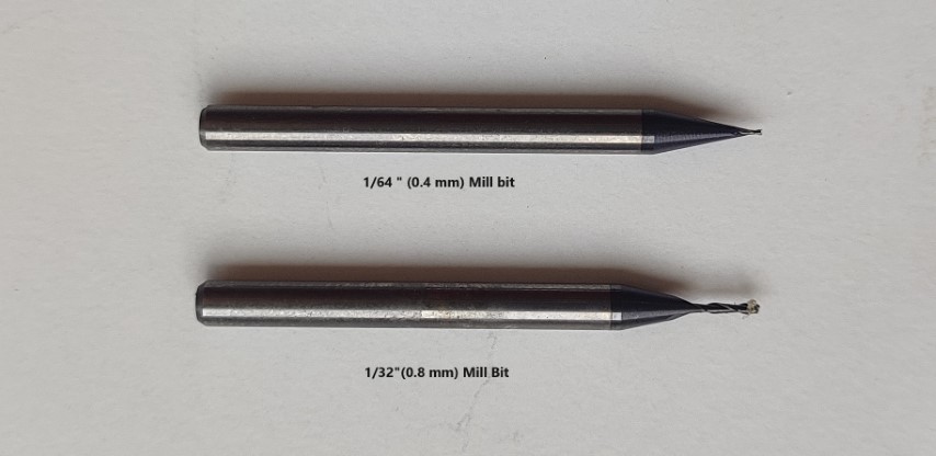
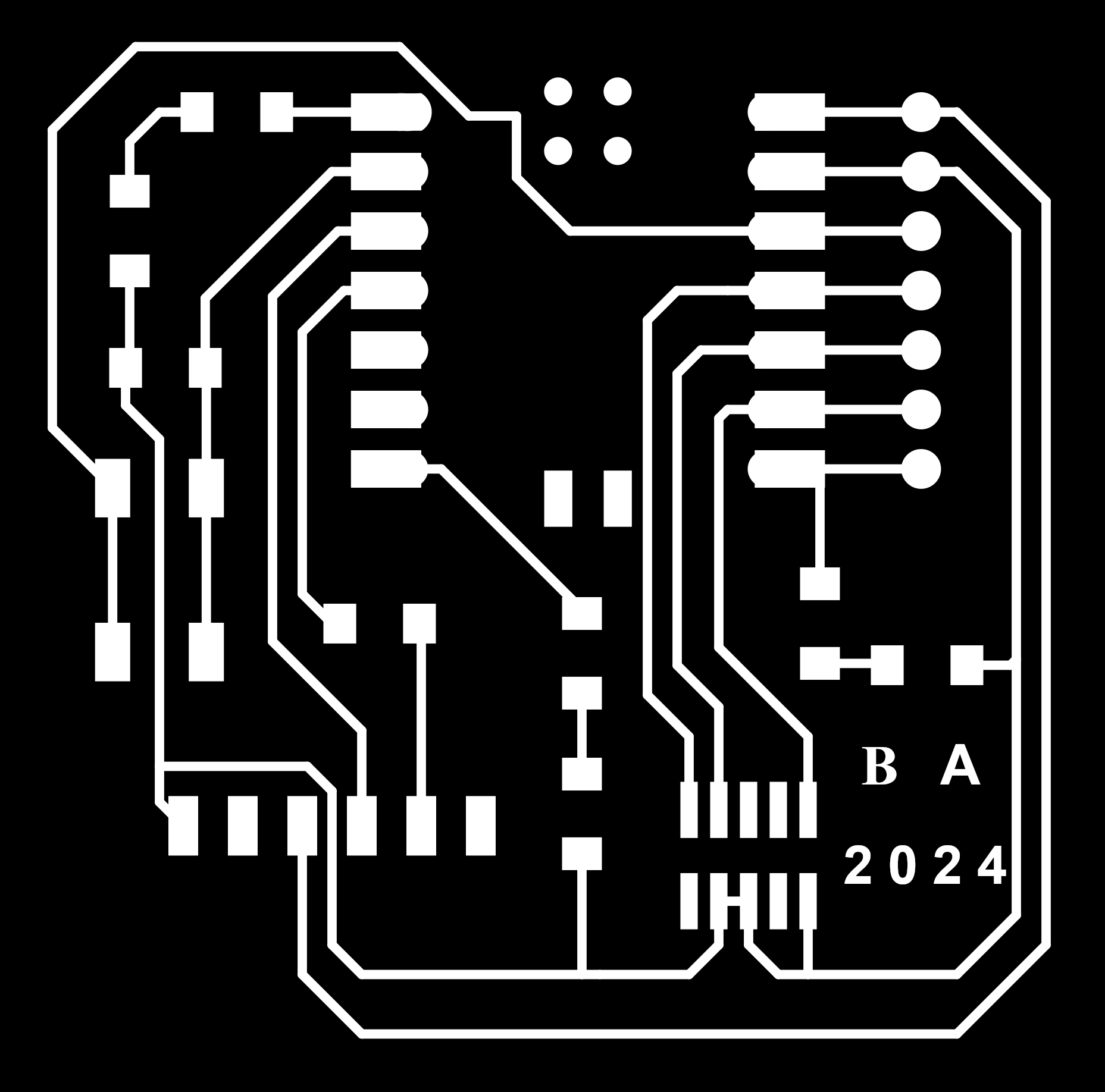
The final result of the finished PCB for the line test looks like this. The test demonstrates that we can achieve trace widths as narrow as 0.001 inches (0.0254 mm) using a 0.4 mm (1/64") flat endmill with proper calibration. For comparison, we also conducted a test with a 0.8 mm (1/32") flat endmill. The picture illustrates the difference, we can't get accurate traces with the 0.8 mm flat endmill.
Group Assignment Page Link- Click here
.jpg)
PCB Milling
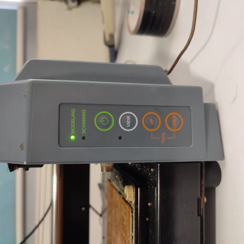
To produce a PCB, we will utilize the ROLAND MODELA MDX 20 "PCB" milling machine at our fabrication facility. This machine boasts a bed size measuring 220mm (X) x 160mm (Y) and offers a precision of approximately 0.006mm. The Roland Model MDX-20 is specifically engineered as a desktop milling machine, adept at crafting precise models and prototypes from various materials, including plastic, wood, and metal.
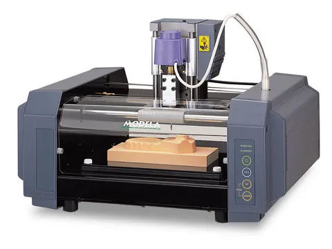
Specifications
| Tool chuck | 6 mm or 1/8 in. tool chuck included |
| Spindle motor | 10W (DC motor) |
| Software resolution | 0.025 mm/step (0.000984 in./step) |
| Mechanical resolution | 0.00625 mm/step (0.000246 in./step) |
| Revolution speed | 6,500 rpm |
| Feed rate | 0.1 to 15 mm/sec. (0.00393 to 9/16 in./sec.) |
| Acceptable material | Wood, Plaster, Resin (modeling wax, styrenform), Chemical wood |
| Acceptable tool | Endmill, Drill |
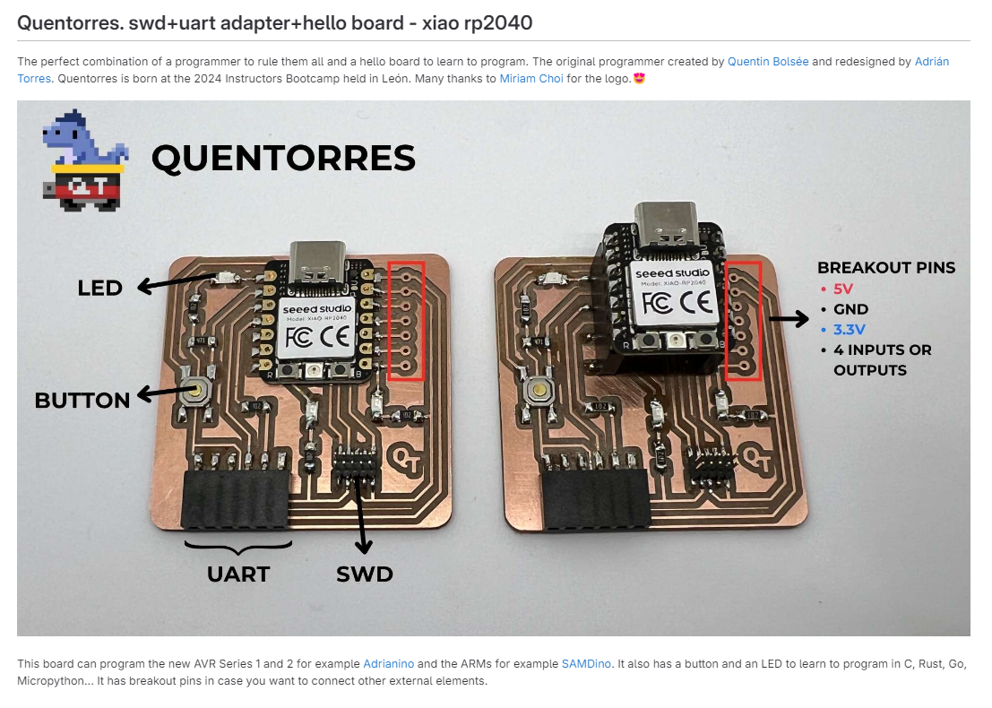
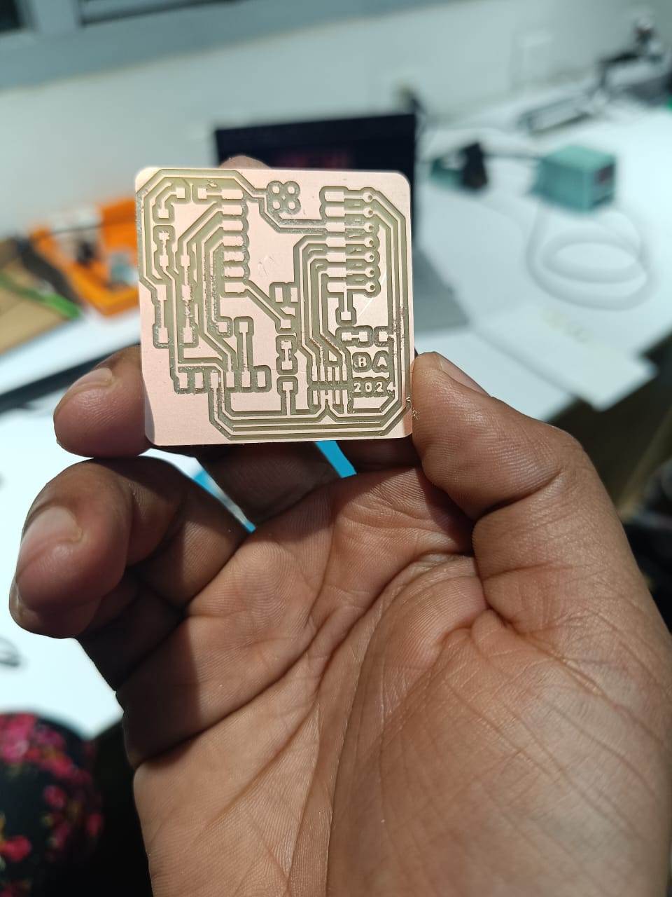
For milling PCB we are milling Quentorres. swd+uart adapter+hello board - xiao rp2040 the design is available at fab academy schedule
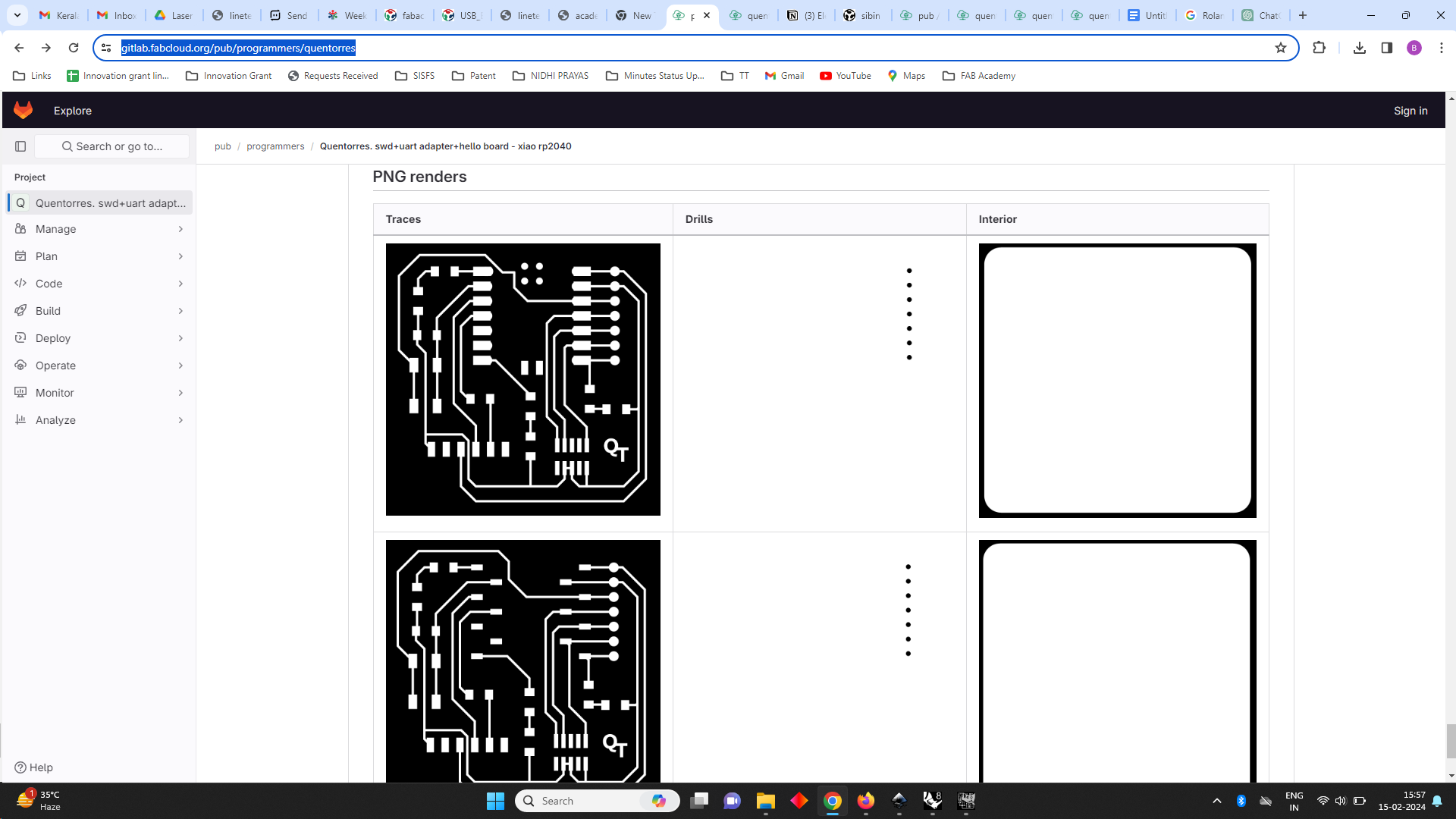
Then I personalized to my Board using GIMP
I have opened the png File in GIMP and changed the board name
.png)
Using text tool i have changed the name
.png)
Then I exported to .png format for milling
Fab Mods
We use FAB MODs to control the machine. I already have some experience in using MODs during the third week for vinyl cutting.
- navigate to the Fab Mods directory in the terminal and execute the "start-servers" file using the following command:
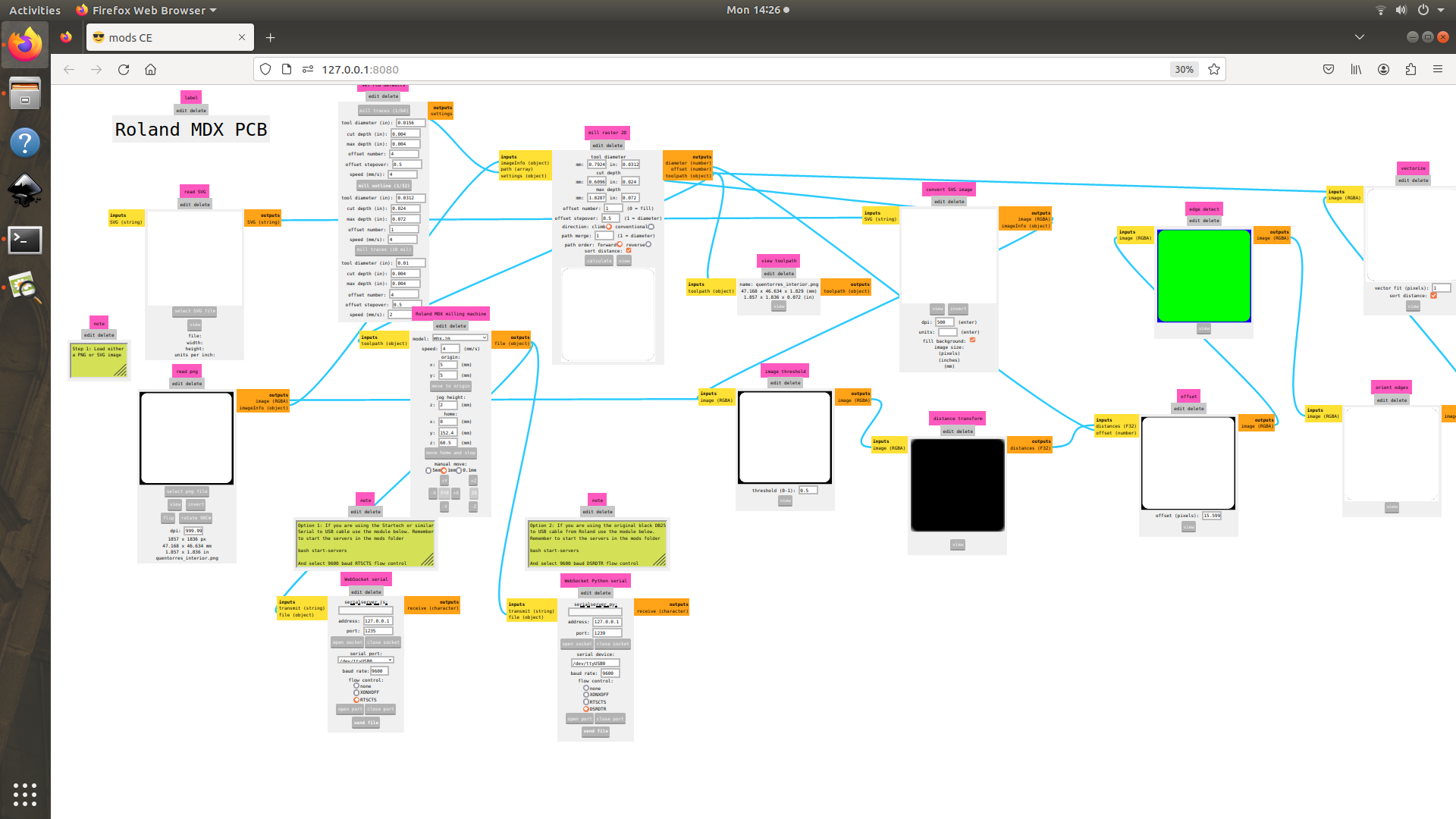
bash start-serversright-click on the screen>programs>open program and this page appears, from this choose PCB under MDX mill
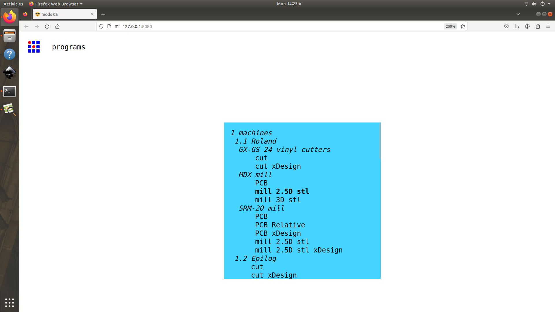
I uploaded my file as .png and then chose 1/64" as my milling tool and selected calculate.
Then calculated and click send file
Then for drilling and edge cutting the tool is changed to 1/32"
For Drilling i have imported the drilling files to Fab Modes
.png)
For cutting the outer shape, the png file is imported to FAB Modes
Milling Procedure
Selection of tools
For milling the PCB we have to use 0.4 and 0.8 mm bits.
0.4mm bit for tracing the paths and 0.8mm bit for cutting the outer border
Here i used used board of dimetions 47mm x 47mm it is a standard size
- Apply double side tape on the other side of FR1 sheet
- stick the pcb to the bed
Changing the tool
Using an allen key change the tool of 0.4 mm mill bit for tracing the path
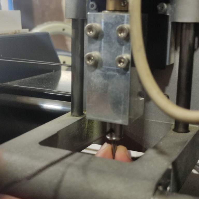
Next, position the spindle at the top of the PCB using coordinates of X 50 -Y 50. Then, lower the z height until it nearly touches the board. After that, release the bit and carefully bring it into contact with the board manually.
Then started the milling by sending files via MODS
The next phase entailed drilling the requisite holes and carving out a border for the milled PCB. We obtained the relevant .png files from Fabcloud and imported them onto MODs.
Following this, I switched to a 0.8mm (1/32") bit, ideal for cutting and drilling, and proceeded with the same procedure. Below is the final result.
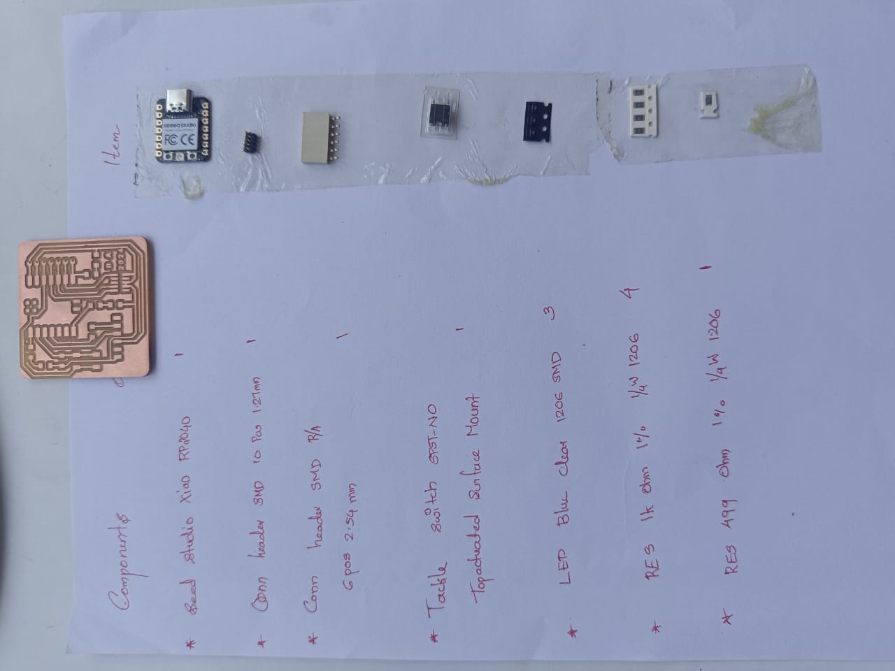
Selecting the components
At our Fablab, we use inventory.fablabkerala.in to request components available in our inventory. After receiving login credentials, I proceeded to add the required components to the cart based on the provided list and submitted the request. Upon approval by the Admin, I then collected all the necessary components
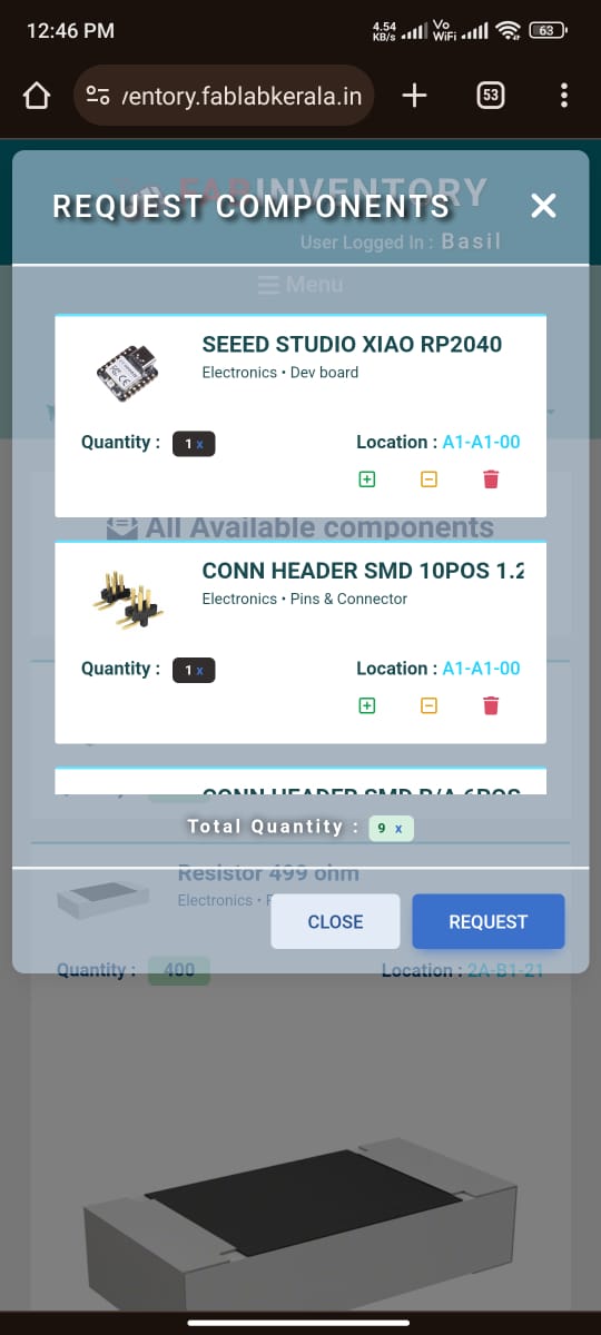
After approval i have collected all items from our inventory and pasted on my Paper
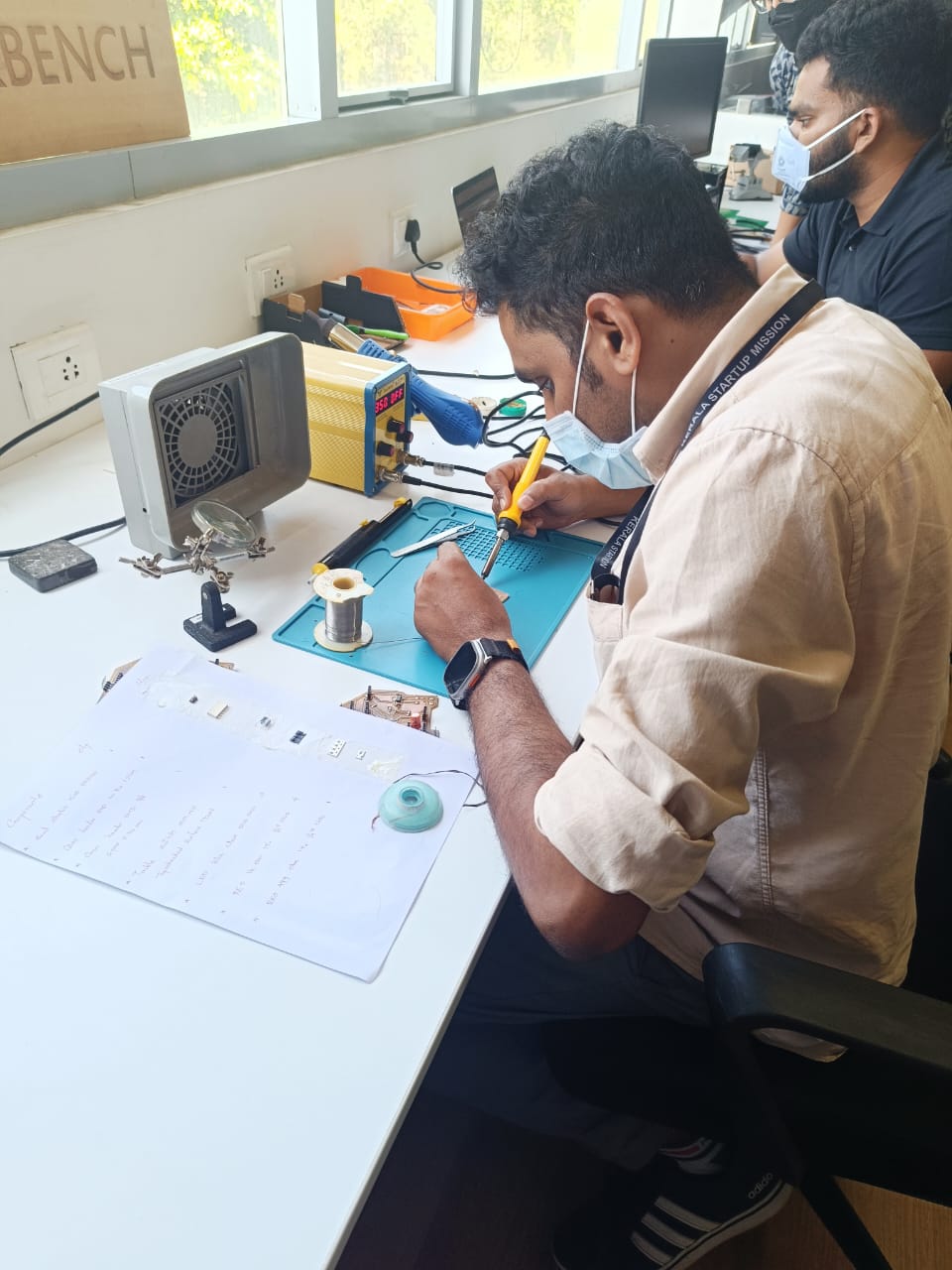
Soldering
Soldering is a process of joining two metal surfaces together using a filler metal called solder. The soldering process involves heating the surfaces to be joined and melting the solder, which is then allowed to cool and solidify, creating a strong and durable joint.
.png)
- Soldering Station:
A soldering station is like a control center for soldering. It's a device with a base where you can place your soldering iron when not in use. Some models allow you to control the temperature for precise soldering work.
- Soldering Iron:
A soldering iron is the tool you use to melt solder and join electronic components together. It's like a pen with a heated metal tip that you can hold and use to make connections.
- Silicone Mat:
A silicone mat is a heat-resistant pad that protects your work surface from damage when soldering. It's like a cushion that prevents burns and keeps your workspace clean.
- Solder:
Solder is a metal alloy that melts at a low temperature and is used to make electrical connections. It's like the glue that holds electronic parts together.
- Tweezers:
Tweezers are small tools with fine tips that help you handle tiny electronic components. They're like tiny fingers that allow you to pick up and place parts precisely.
- Desoldering Pump:
A desoldering pump is a tool used to remove excess solder from joints. It's like a vacuum cleaner for solder, sucking up molten metal so you can start fresh.
- Desoldering Wick:
Desoldering wick is a braided copper wire coated with flux. It's like a sponge that soaks up melted solder, helping you clean up messy joints and fix mistakes.
Safety Measures While Soldering
- Never touch the tip or element: It gets extremely hot (around 400°C) and can cause severe burns.
- Use safe handling tools: Hold hot wires with tweezers, pliers, or clamps to avoid burns.
- Keep the cleaning sponge wet: This prevents fire hazards and helps clean the tip effectively.
- Use a stand: Always return the iron to its stand when not in use, never leave it on the workbench.
- Inspect cords regularly: Check for damage like fraying or cracks before each use. Replace faulty cords immediately.
- Unplug when not in use: This reduces the risk of electrical accidents.
- Choose a fire-resistant surface: Wood or paper should be avoided. Invest in a heat-resistant soldering mat.
- Maintain a clean and organized workspace: This minimizes clutter and potential fire hazards.
- Ensure proper ventilation: Solder fumes can be irritating and harmful. Use a well-ventilated area (open windows/fans) or a fume extractor.
- Wear appropriate clothing: Long-sleeved shirts, pants, and closed-toe shoes protect you from hot solder splashes and burns.
- Eye protection is essential: Wear safety glasses or goggles to shield your eyes from hot solder splatter and debris.
Soldering
In orfer to solder the components to the Quentorres. swd+uart adapter+hello board - xiao rp2040 i have used the circuit diagram
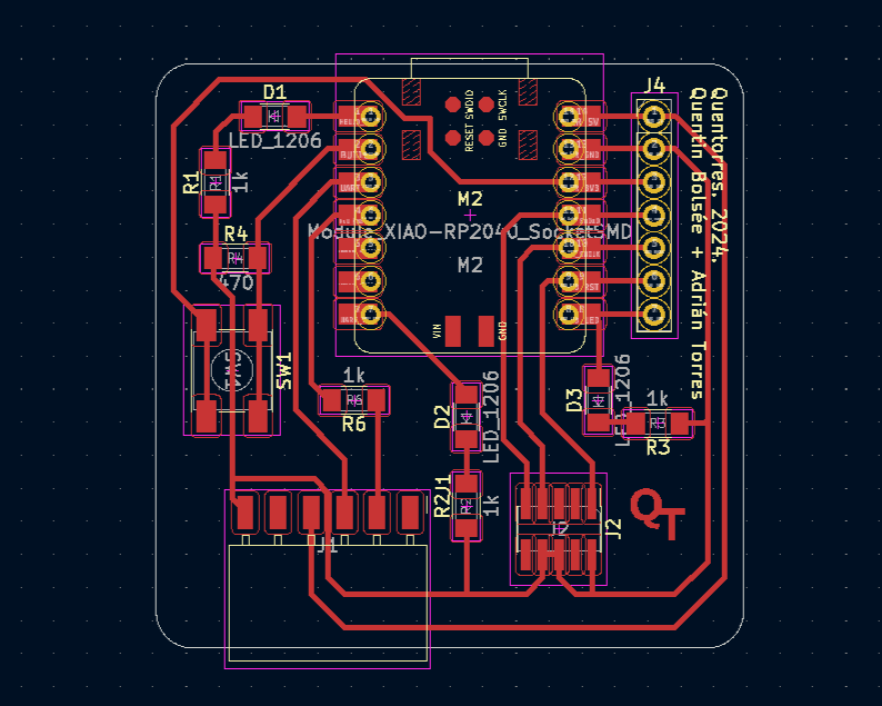
Soldering surface-mount (SMD) components can pose a challenge as it demands the use of both hands to accurately apply the solder. To tackle this difficulty, I utilized a method where I initially applied solder to one of the pads before positioning the component. This method ensured the accurate alignment and secure attachment of the component to the board.
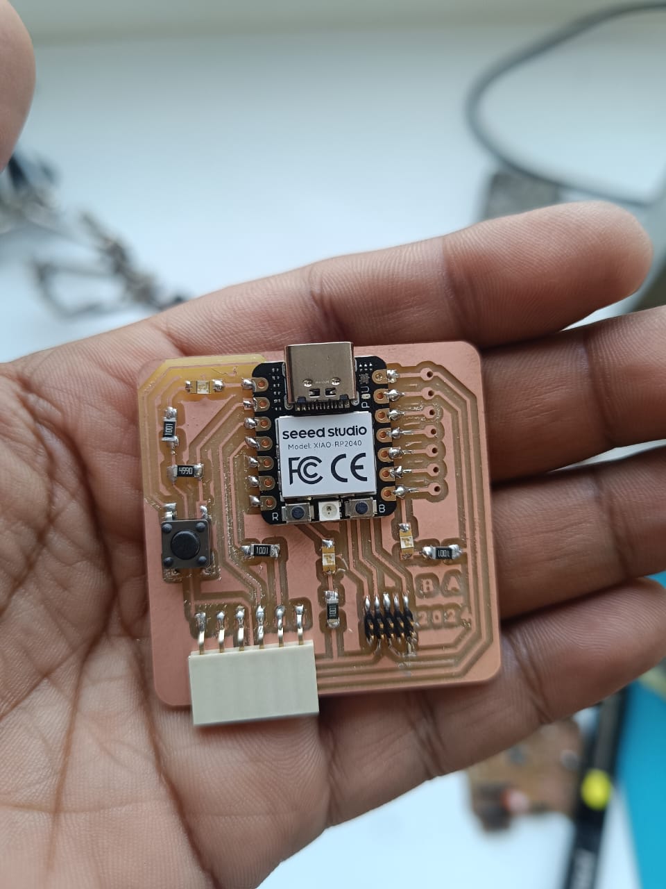
Final Result
Blinking LED
I downloaded Arduino IDE 2.3.1 from website
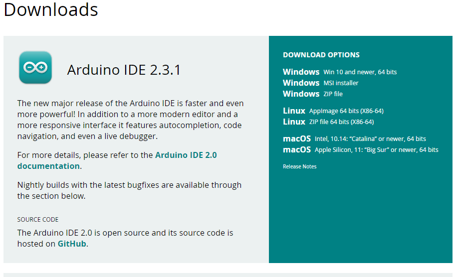
I followed to the instructions provided on the website.
I simply needed to add the board by navigating to File > Preferences > Board Manager and pasting the link for the Arduino-Pico package.
https://github.com/earlephilhower/arduino pico/releases/download/global/package_rp2040_index.json
.png)
Then, open Tools > Board > Board Manager. Type "pico" on the search bar and download Raspberry Pi Pico RP2040.
.png)
Following the installation process, I selected the board by navigating to Tools > Boards > Raspberry Pi Pico/RP2040 > Seeed XIAO RP2040.
.png)
Then i modified the code for blink LEDs
void setup()
            {
              pinMode(26, OUTPUT);
              pinMode(0, OUTPUT);
              pinMode(1, OUTPUT);
            }
            // HIGH and LOW are the voltage levels
            void loop()
            {
              digitalWrite(26, HIGH);
              delay(100);
              digitalWrite(26, LOW);
              delay(100);
              digitalWrite(0, HIGH);
              delay(100);
              digitalWrite(0, LOW);
              delay(100);
              digitalWrite(1, HIGH);
              delay(100);
              digitalWrite(1, LOW);
              delay(100);
            }
This was the results
Reflow Soldering
Reflow soldering is a common method used in electronics manufacturing to solder surface-mounted components onto printed circuit boards (PCBs). In reflow soldering, solder paste—a mixture of tiny solder particles and flux—is applied onto the pads of the PCB where components will be placed. The components are then accurately placed onto these pads using pick-and-place machines.
For Reflow soldering we have used Saheen Palayi's 'ProshPlay' board design.
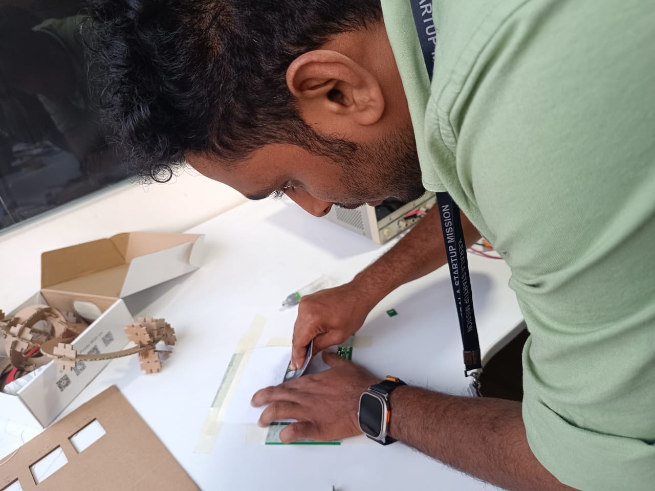
So initially, we have set up a stencil for placing the board
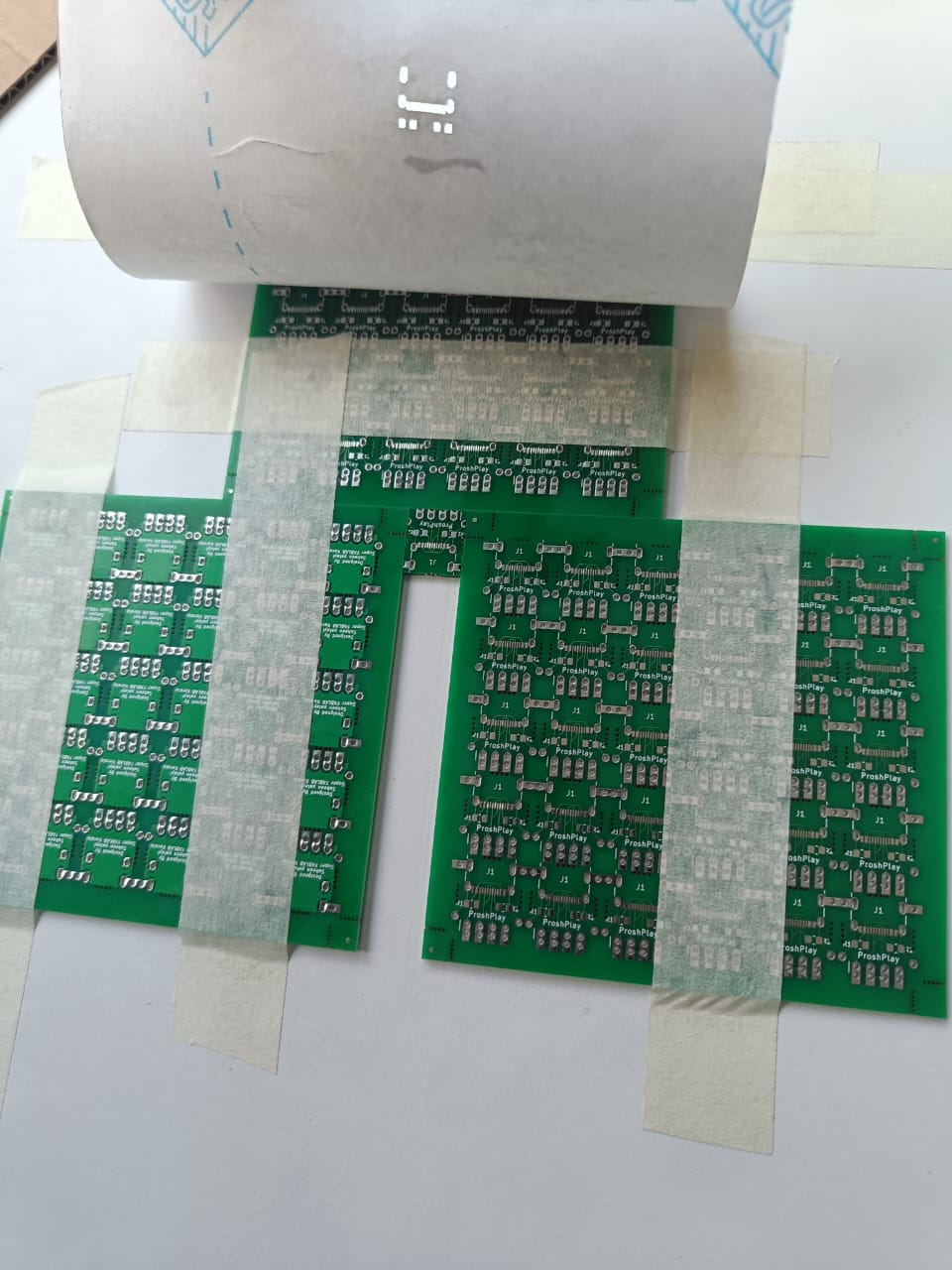
We have used Solder Flux,SMD291AX250T5
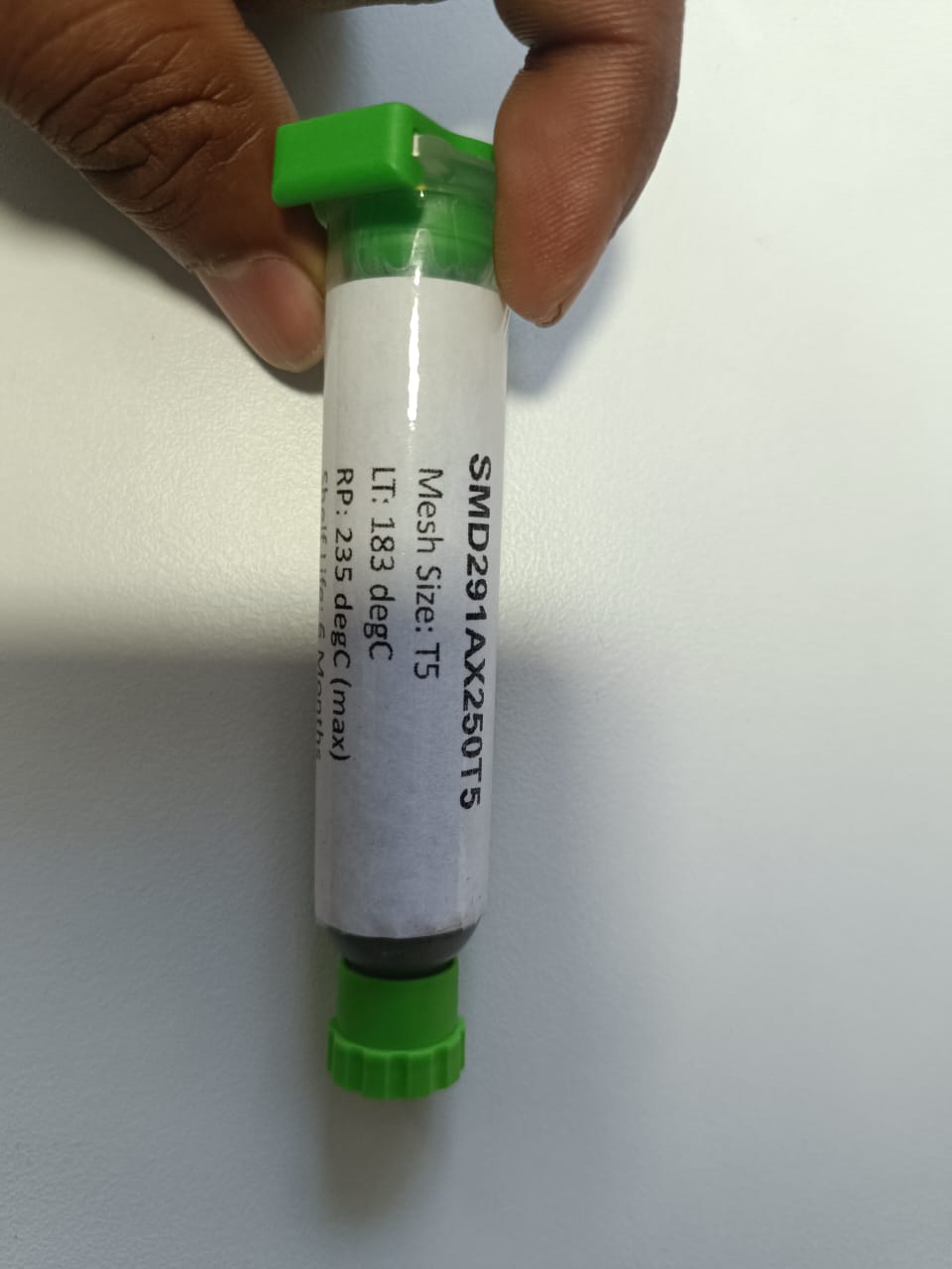
After placing the board into stencil, Applied the solder flex
We have already collected Files 5.1K resistors and Type C port for the board
.jpeg)
Then i have placed the components using a tweezer , Finally it looks to go for Oven
.jpeg)
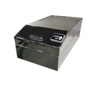
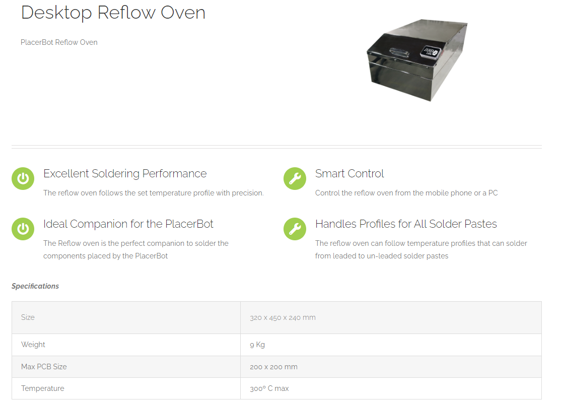
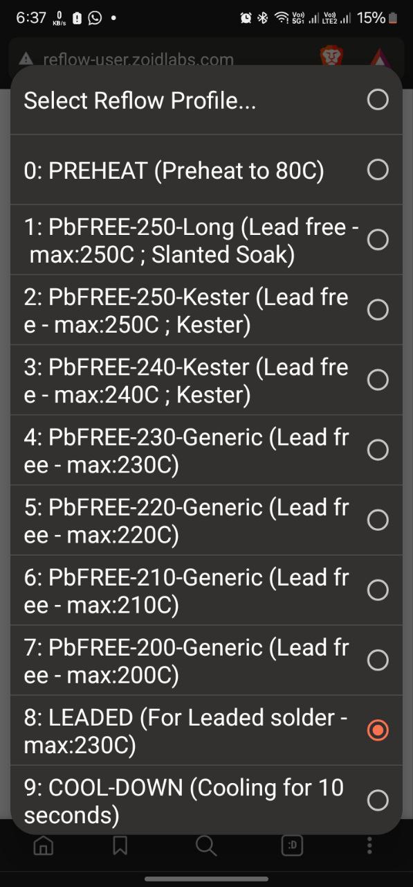
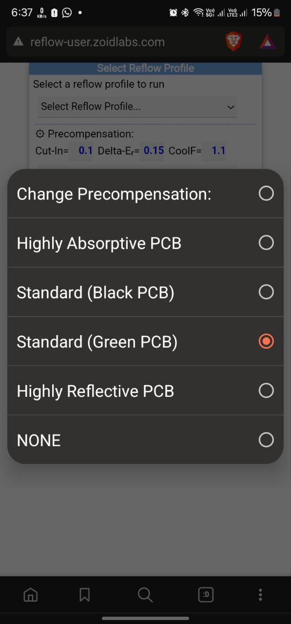
We have oven designed by ZOID LABS a KSUM registered Startup They offer a mobile interface accessible through WiFi connection to the device, allowing us to monitor temperature fluctuations across various specified phases.
Preheat Phase: The PCB assembly is gradually heated to dry the paste and activate the flux, a chemical agent in the solder paste that cleans metal surfaces to improve the solder's ability to bond.
Soak Phase: The temperature is raised further to achieve uniformity across the entire assembly, preventing thermal shock to components and ensuring even melting of solder.
Reflow Phase: The temperature is elevated above the solder's melting point, typically ranging from 183°C to 250°C for lead-free solder. This causes the solder paste to melt, flow, and create solder joints.
Cooling Phase: Subsequently, the assembly undergoes controlled cooling to solidify the solder, resulting in robust electrical and mechanical connections.
The steps follows
.jpg)
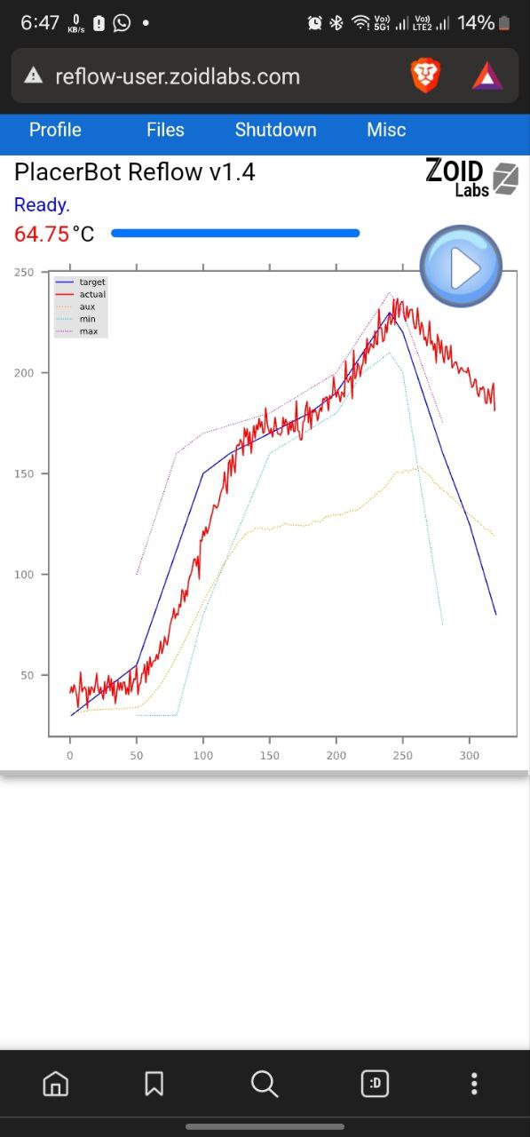
Once it is completed its cooling phase , We can open the oven
The results are shown bleow
.jpeg)
Inspection and Observation
I have inspected the board using Microcpe the image is putting below
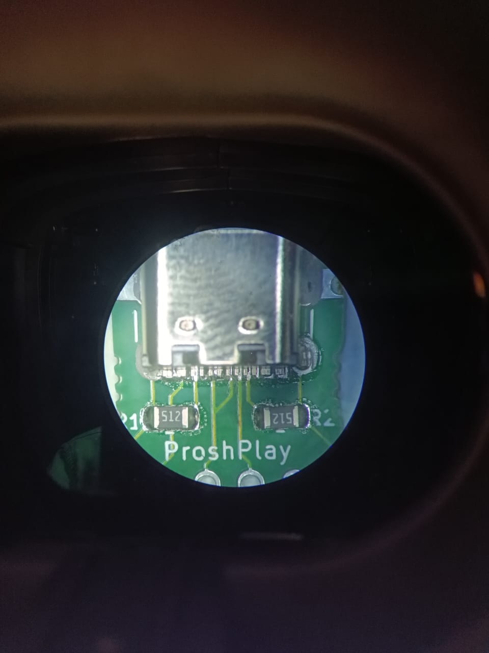
Observation: Two pins have become shorted. Upon cross-checking with my instructor, it was explained that this occurred due to excess solder flux and temperature variation in the oven, particularly at the edge side.
Correcting the Proshplay
To correct shorted pins caused by excess solder flux and temperature variation, first apply flux to the faulty connections and use a hot air gun set at around 300-350 degrees Celsius to reflow the solder. This helps remove excess material, which can be extracted with tweezers or a solder wick. Afterward, apply soldering paste to the connections and ensure proper alignment of components. Place the circuit board in a reflow oven, following the recommended temperature profile, which typically includes a gradual temperature rise, a peak for reflow, and a controlled cool-down. After reflowing, inspect the board for shorts or misaligned components, then test its functionality to ensure the problem is resolved. Ensure you're working in a well-ventilated area and wearing appropriate safety gear throughout the process.