Computer Controlled Cutting
Task for this week:
Individual assignment:
- cut something on the vinylcutter
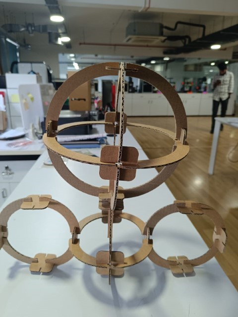
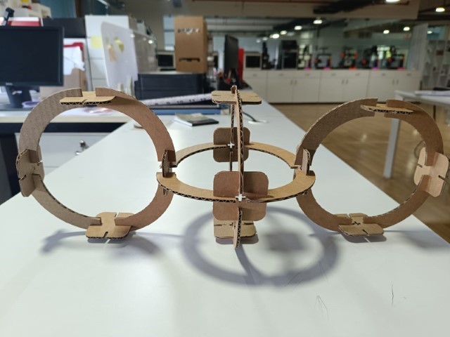
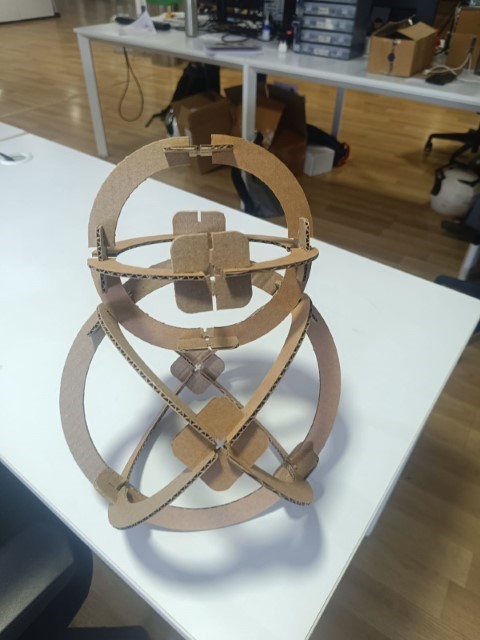
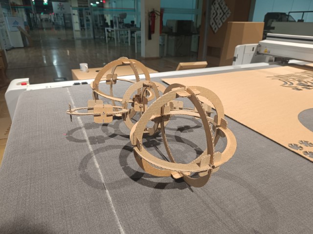
- design, lasercut, and document a parametric construction kit accounting for the lasercutter kerf,
which can be assembled in multiple ways,
Group assignment:
- characterize your laser cutter's focus, power, speed, rate, kerf, joint clearance and types.-Link to group assignment
Vinyl Cutter
A Vinyl Cutter is a computer-controlled machine that allows us to make precise cuts on vinyl sheets. Vinyl cutters typically use a knife held by the cutting carriage to make these precise cuts
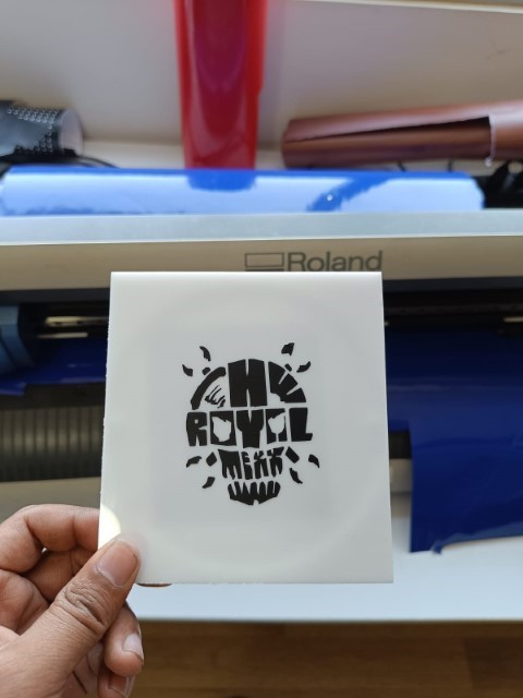
We have a Rolend GX-24 Vinyl Cutter in our lab.
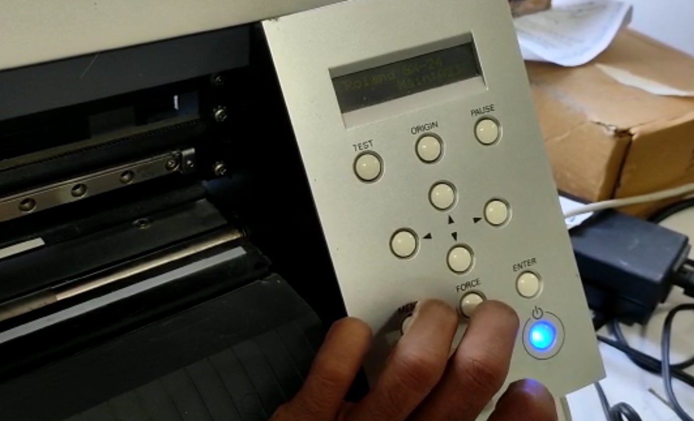
To start the vinyl cutting machine, press the Blue button on the right side of the control panel. Choose whether you're using a roll or a piece of material. If it's a piece, the machine will figure out its size, and if it's a roll, it'll measure the width. Put the material in through the back like a printer.
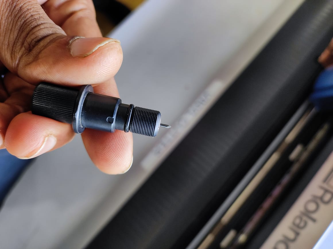
Cutting tool
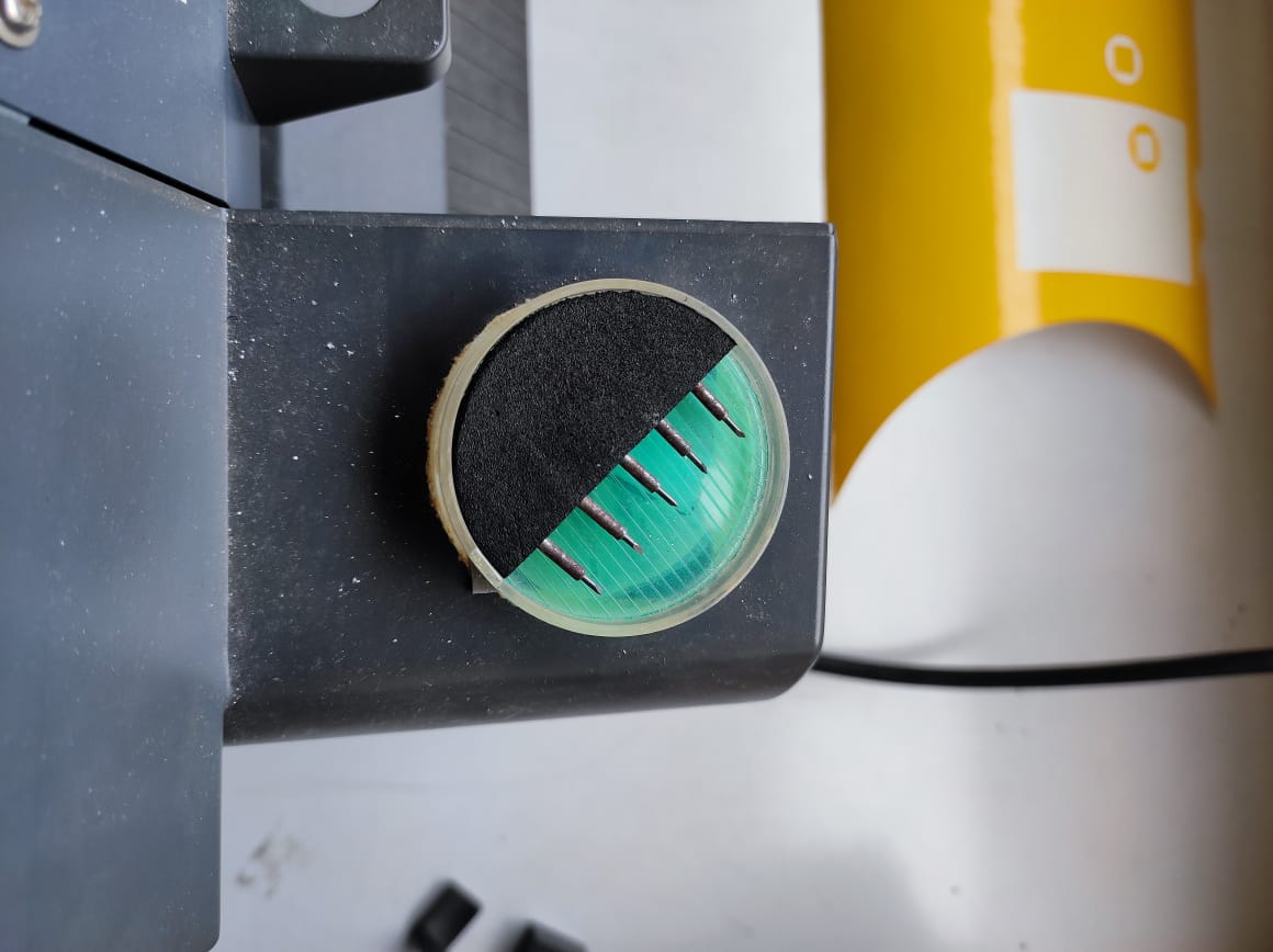
Set of Blades
For this week, I tried cutting a small sticker of fablab logo.
I used Inkscape to vectorize the image. Using 'Trace Bitmap' tool, I made a vector image and exported it as .png file.
.png)
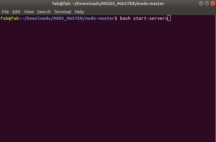
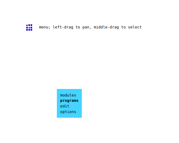
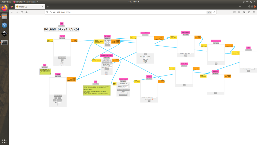
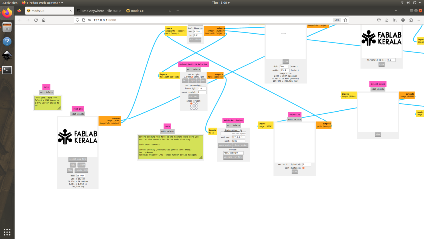
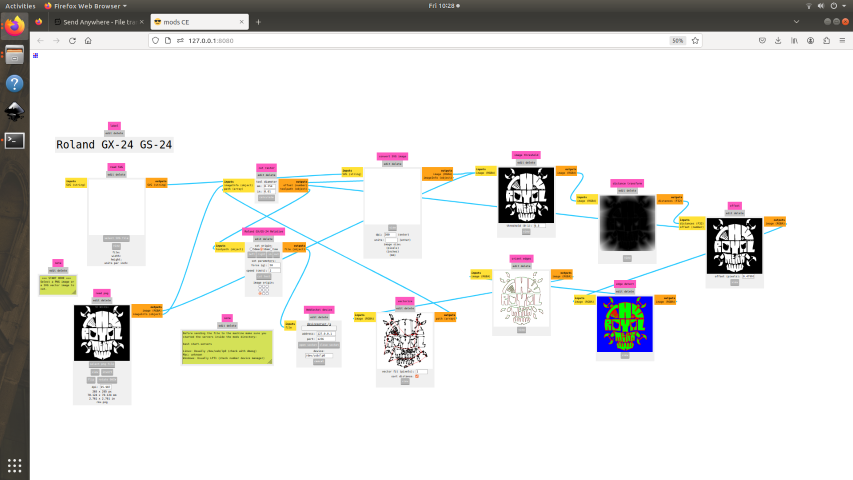
I opened the png file in Fablab mods on a desktop computer which was connected to the vinyl printer . Mods is a versatile and cross-platform tool designed for use in Fablabs . This tool bypasses the need for printer drivers by performing all necessary calculations to convert SVG or PNG files into commands that can be sent to the vinyl cutter. It utilizes a modular approach, allowing multiple machines to be operated as a complete suite when the modules are combined correctly.
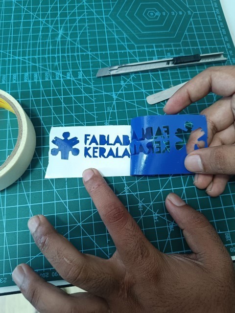
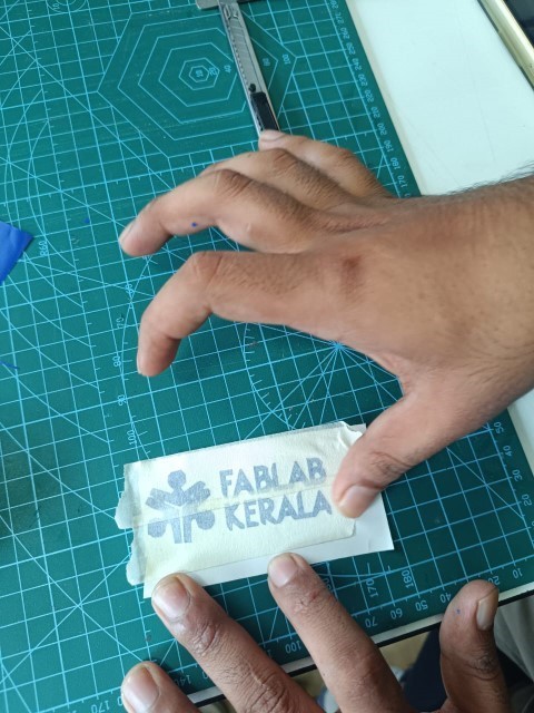
To transfer the design, you will want to apply a layer of transfer paper on top of the remaining design. In this case, a masking tape is used. Ensure that the design is firmly rubbed onto the transfer paper.
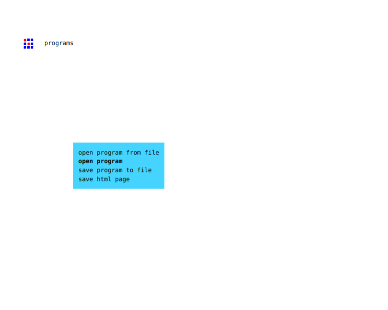
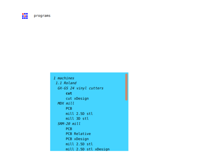
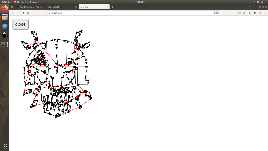
After opening Git bash you will see the interface, In that you can choose your png/svg file
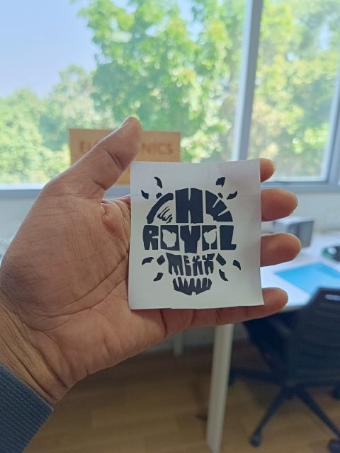
I have cut the image followed the tools & steps to paste it on my table
.jpeg)
.jpeg)
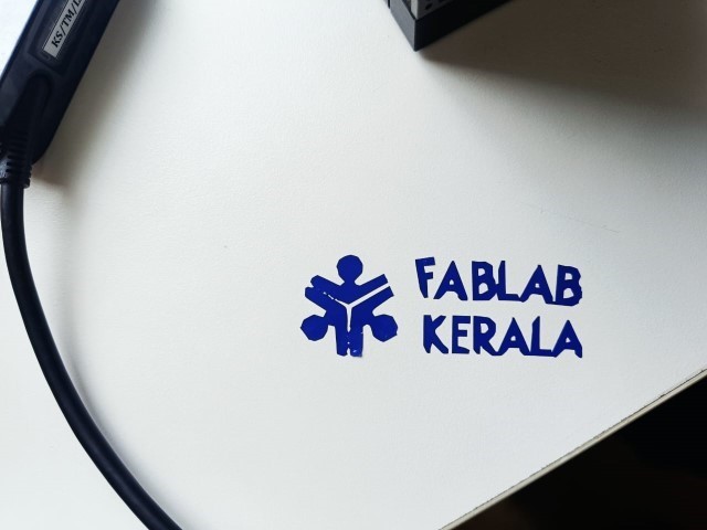
I have made anther sticker followed by the above steps
Parametric Design in Fusion 360
In Fusion 360, parametric design refers to the ability to create models that are driven by parameters, such as dimensions, angles, and relationships between objects. This allows you to easily modify the design by changing the parameters, which will automatically update the model accordingly.
To view parametric settings Click on Design > Solid > Modify > Change Parameters
.png)
.bak.png)
By adjusting the parametric variables,we can see the changes in the overall size
.png)
Next, I created two designs using the pattern tool, which is located under Solid > Create > Pattern > Rectangular Pattern.
Instructions for creating patterns:
- Select the objects you wish to pattern from the browser.
- Specify the desired number of rows and columns for the pattern.
- Fine-tune the spacing and offset values according to your preferences.
- Choose the direction of the pattern (X, Y, or Z) and select the reference plane or surface.
- Preview the pattern to confirm its accuracy.
- Click "OK" to apply the pattern to the design.
.png)
.png)
Then i have arranged the drawing using Arrange' option in Fusion which can arrange the components in such a way that the gap in between the elements will be small and thereby ensure less waste.
.png)
.png)
After arranging the components, I generated a new sketch by projecting their surfaces. Then, I saved the sketch as a .dxf file.
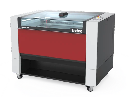
Trotec Speedy 400 flexx
The Trotec Speedy 400 laser is a high-performance CO2 laser engraving and cutting machine designed for both beginners and experienced professionals. It boasts an impressive work area of 40 x 24 inches, making it ideal for a wide range of applications. With engraving speeds of up to 170 inches per second and 5g acceleration, the Speedy 400 is one of the fastest machines on the market, ensuring efficient job completion.
Unfortunately, both of the laser cutting machines at our FAB LAB are currently unavailable due to maintenance. We tried to cut a sample with one of the machines, but it seems that the laser beam lacks the necessary power to cut through the material.
Fortunately, we managed to meet our laser cutting requirements by utilizing a machine at Maker Village. However, we were unable to proceed with our individual projects. Nonetheless, we made use of the opportunity to advance our group project.
ZUND G3 L-2500 Digital Cutter
The ZUND G3 L-2500 Digital Cutter is a powerhouse of precision and versatility, designed for businesses demanding high-quality results and efficient workflows. This modular system boasts a cutting area of over 192" x 108", making it ideal for large-format projects in sign & graphics, packaging, and textile industries. Equipped with an automatic tool changer and self-initializing tools, it tackles various materials up to 4.3" thick, from delicate fabrics to rigid cardboard. Its robust build and Swiss-engineered components ensure accuracy and reliability, while its intuitive software simplifies operation
The Zund Cut Editor software allows users to prepare cutting files, send them to the Zund machine, and control the cutting process. The software includes tools for designing and editing cutting paths, managing materials and tool settings, and optimizing cutting workflows.
To add your dxf file click on file then select Add job
.png)
The Numerical Geometry tool in Zund Cut Editor is used to create and modify cutting paths on digital materials with precision and accuracy. This tool allows users to enter numerical values to define the exact position, size, and orientation of cutting lines, curves, and shapes.
.png)
The method ( type of cut ) is set to Thru-cut . Through-cuts are cuts that go all the way through the material, creating separate pieces that can be easily removed.
.png)
Next method is to provide Register to define the work area border, which was provided as border: front-right.
.png)
To set the material select the pen icon on the right side next to materials . I was going to cut the materials on 3 mm corrugated B-flute. click and select the OK to set the material
.png)
Zund cut que software allows users to manage and organize their cutting jobs in a queue. The Cut Queue enables users to add, delete, and modify cutting jobs in a list or queue, and to prioritize and manage the order in which the jobs are processed.
.png)
In Cut center double click on the tru-cut tab on machining steps a popup window opens to select the right tool . By default EOT, EOT refer to the universal cutting tool and electrical oscillating tool positions of the cutting head, respectively.
.png)
after selecting EOT there are option to set speed , feed and acceleration .
.png)
To start the cutting process, press start job button
Files
- Logo for Vinyl Cutter - Logo
- Parametric Desin -Design