Final Project
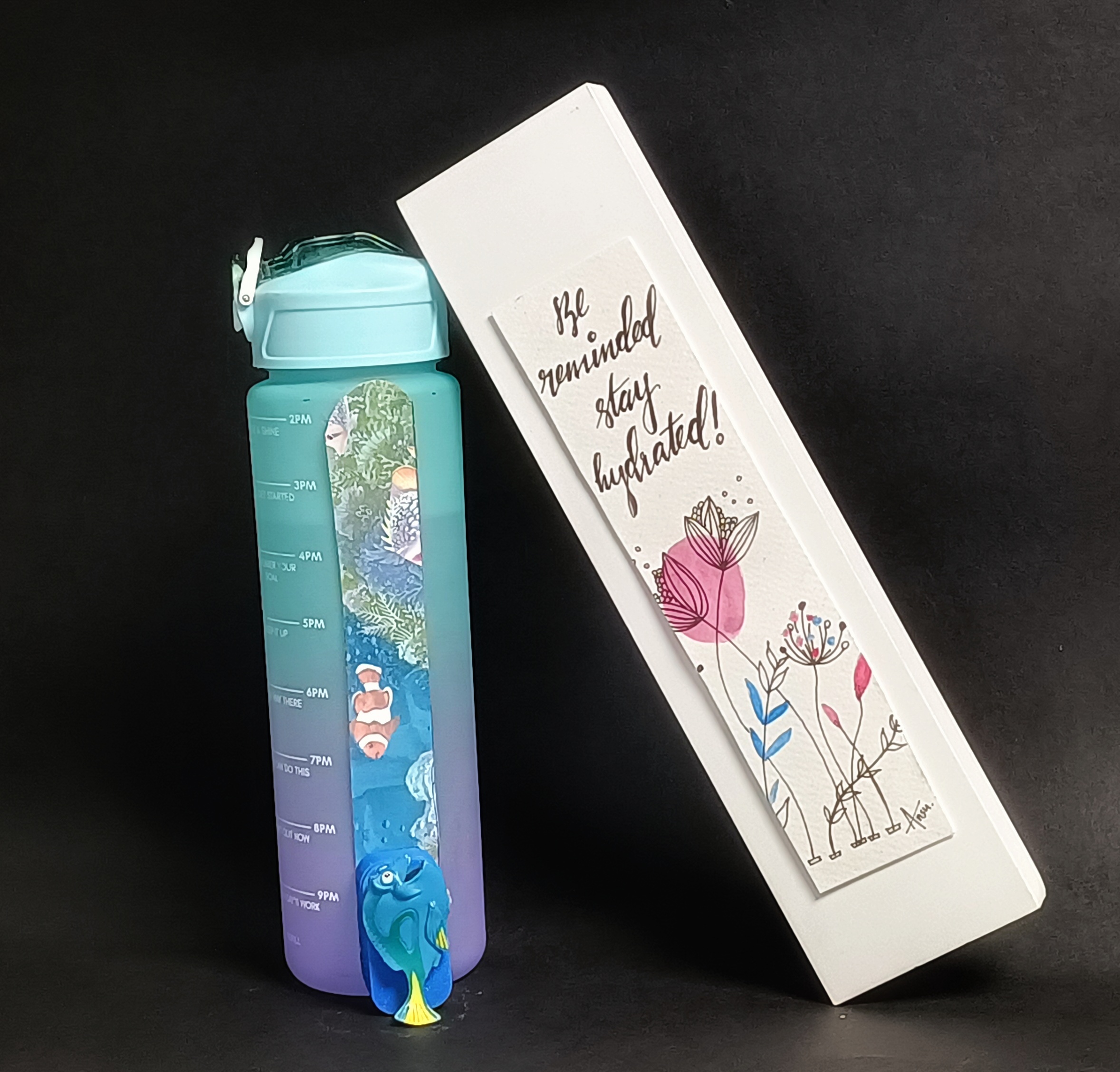
Stay hydrated, Be reminded!!
Final Project presentation video
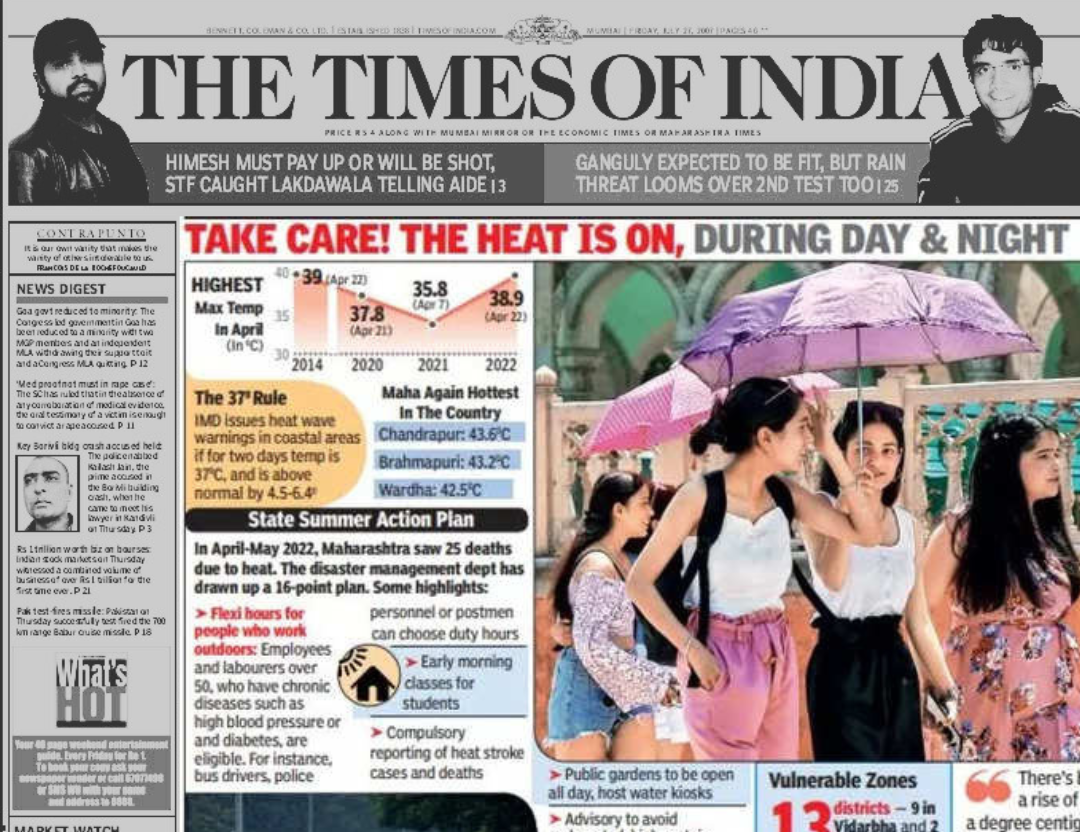
With Kerala's sweltering summers hitting hard, the newspapers buzz with warnings about the brutal heat and keeping hydrated during this time is a must.
.jpg)
.jpg)
.jpg)
.jpg)


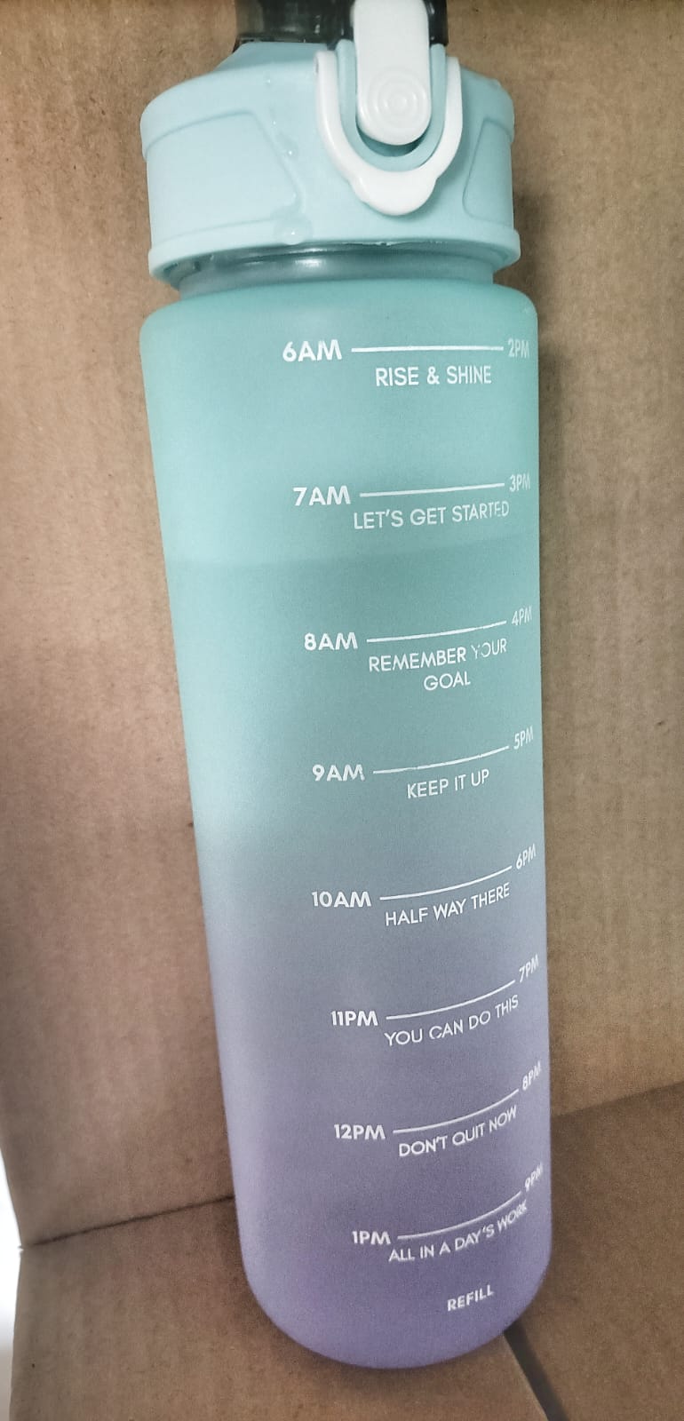
So, I decided to buy a bottle which indicates time and the amount of water that needs to be consumed within that time.
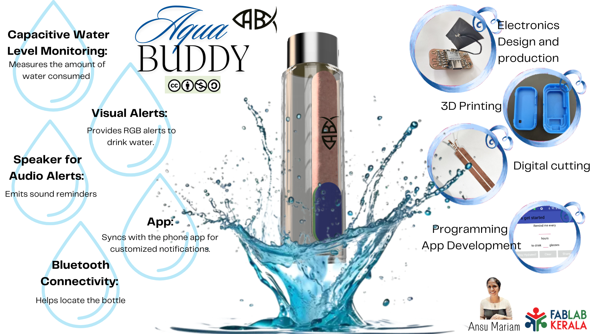
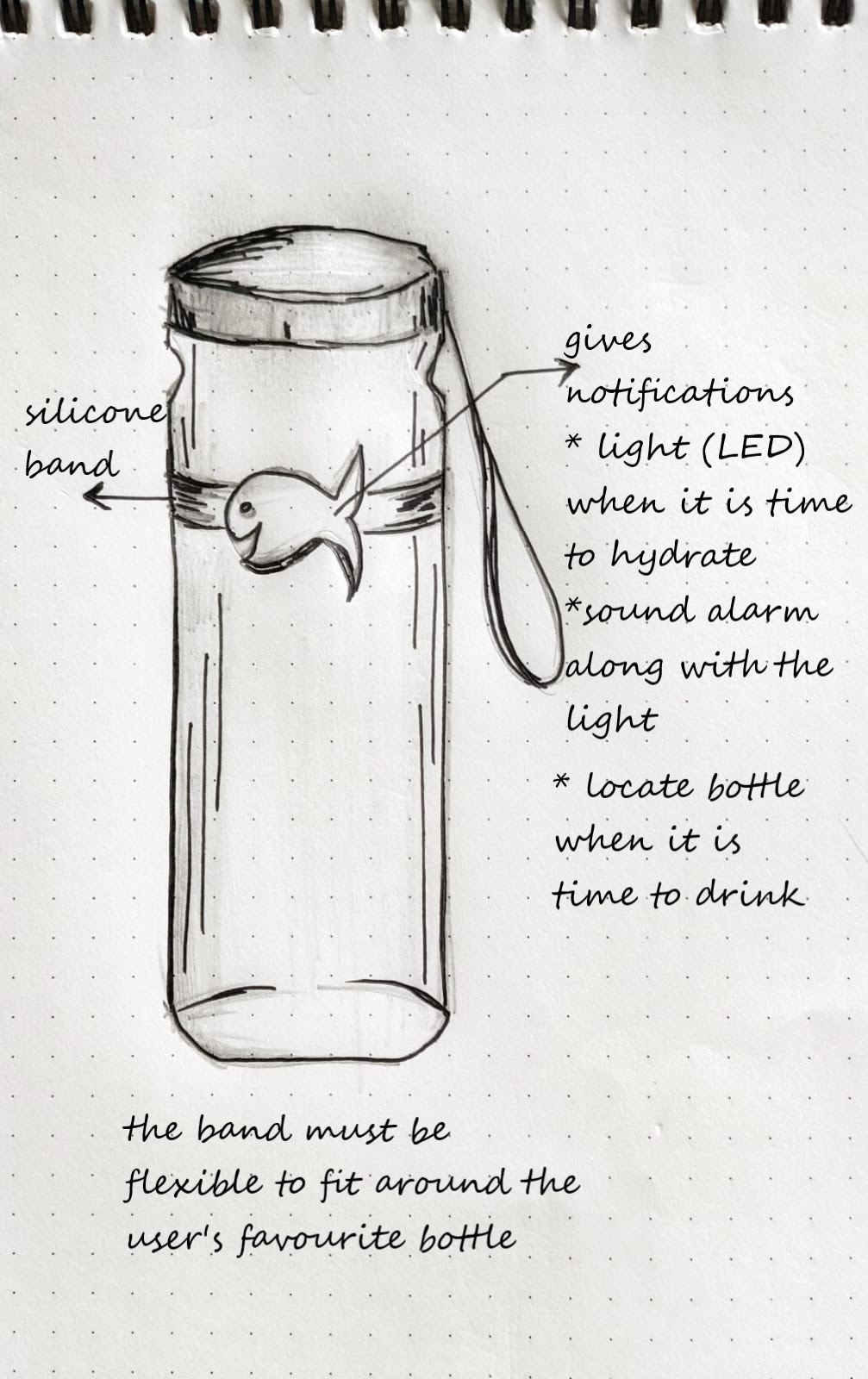
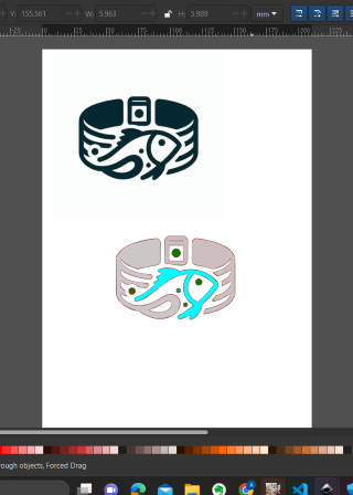
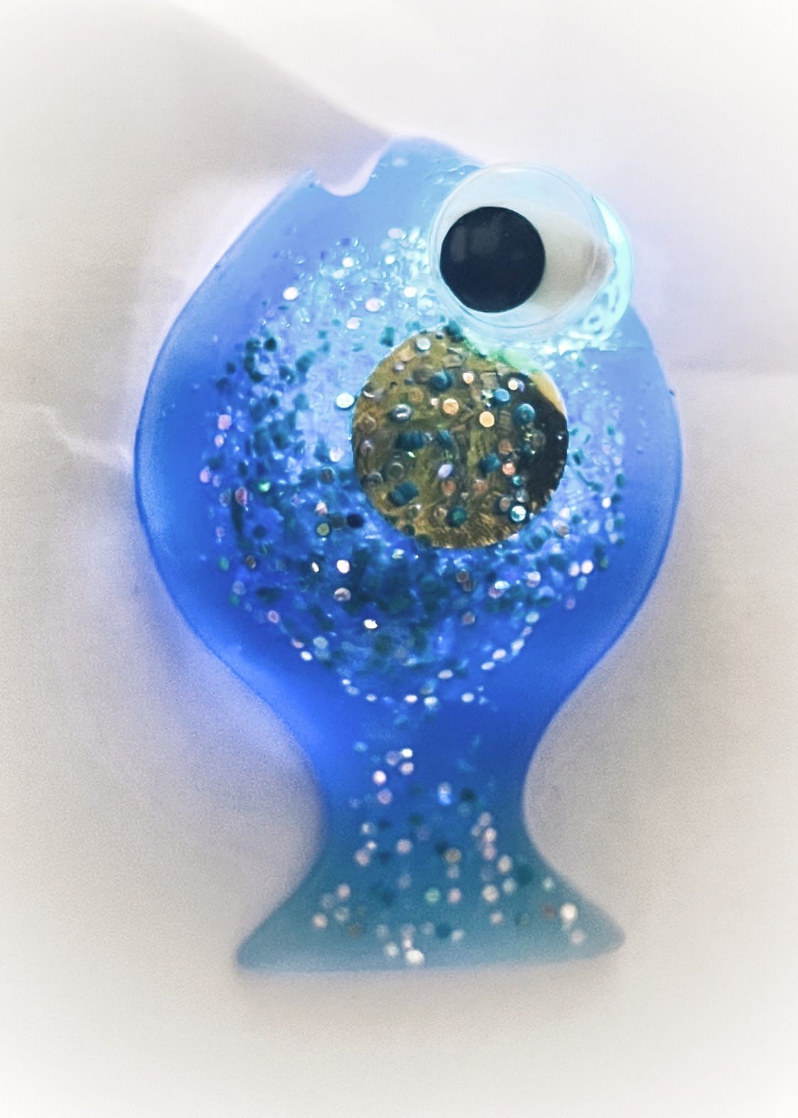
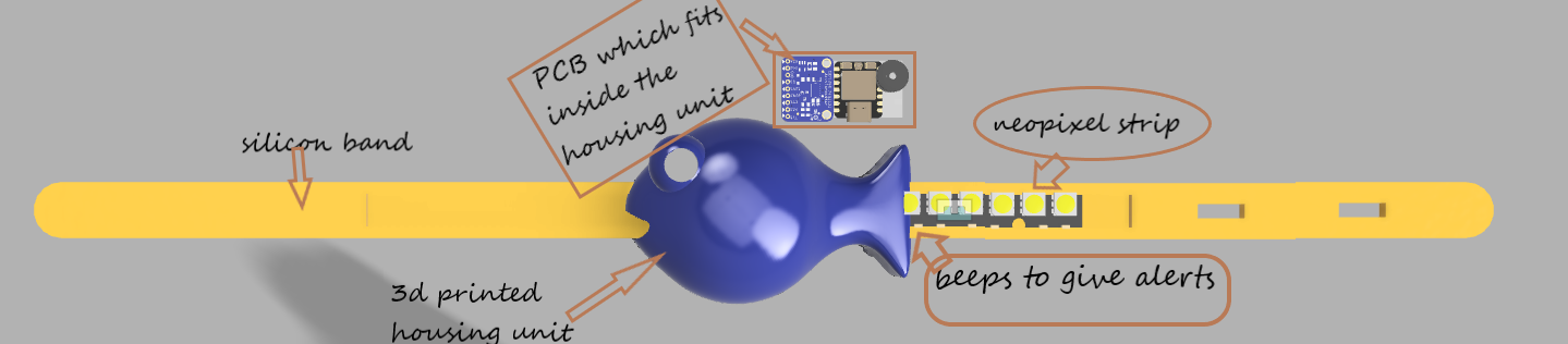
But that didn't help either!! I would still forget to drink water and that is when I thought of an AquaBuddy for my final project. The Aquabuddy is a band which can be put on your favourite bottle, to remind you to stay refreshed. The reminder band would work to encourage hydration by detecting periods of inactivity and reminding the user to drink water at regular intervals.The band not only reminds you to sip but also helps you locate your bottle when it's time to drink and you dont remember where you kept your bottle. Sporting a cute fish indicator, symbolizing water's importance, and featuring everyone's favorite forgetful fish, Dory, from "Finding Nemo," the band adds a fun twist to hydration. My final project plan is to make a reminder band which can be used on your favourite bottle..
Features of the Aqua Buddy
- Sensing Motion: The band would contain sensors to detect motion or movement, such as an accelerometer or gyroscope. These sensors would continuously monitor the position and orientation of the water bottle.
- Detecting Inactivity: The band would analyze the data from the motion sensors to determine periods of inactivity. For example, if the water bottle remains stationary for a certain duration, it indicates that the person hasn't lifted the bottle to drink water.
- Triggering Reminders: Once the band detects prolonged inactivity, it would trigger a reminder to encourage the person to drink water. This reminder could be in the form of a gentle vibration, LED notification, or audible alarm.
- Adjustable Settings: The band could include adjustable settings to customize the reminder frequency and intensity based on individual preferences and hydration needs. For example, users could set the duration of inactivity before receiving a reminder and choose their preferred reminder method.
- Integration with Smart Devices: Optionally, the band could integrate with smartphones or other smart devices via Bluetooth or Wi-Fi connectivity. This integration would allow users to receive notifications on their phones or track their hydration habits using a companion app.
- Power Management: The band would feature efficient power management to ensure long battery life. It may include a rechargeable battery or use low-power components to minimize energy consumption.
- Comfort and Durability: The band should be designed for comfort and durability to ensure it can withstand daily use and be worn comfortably around the water bottle without causing discomfort or hindering usability.
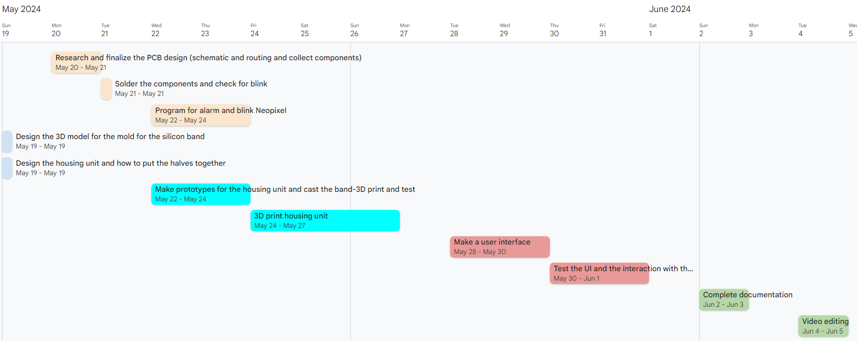
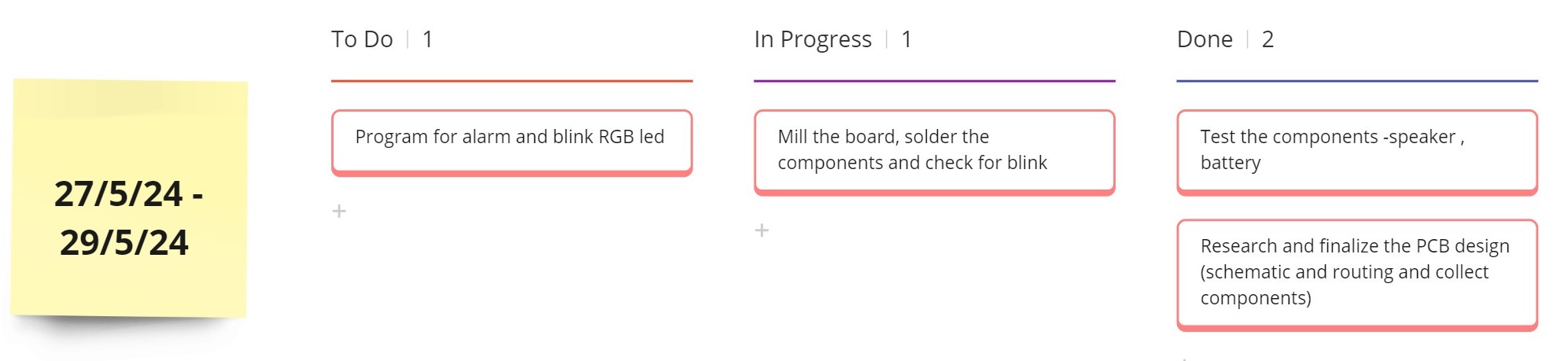
Marching towards the Final Project
Marching week by week.....
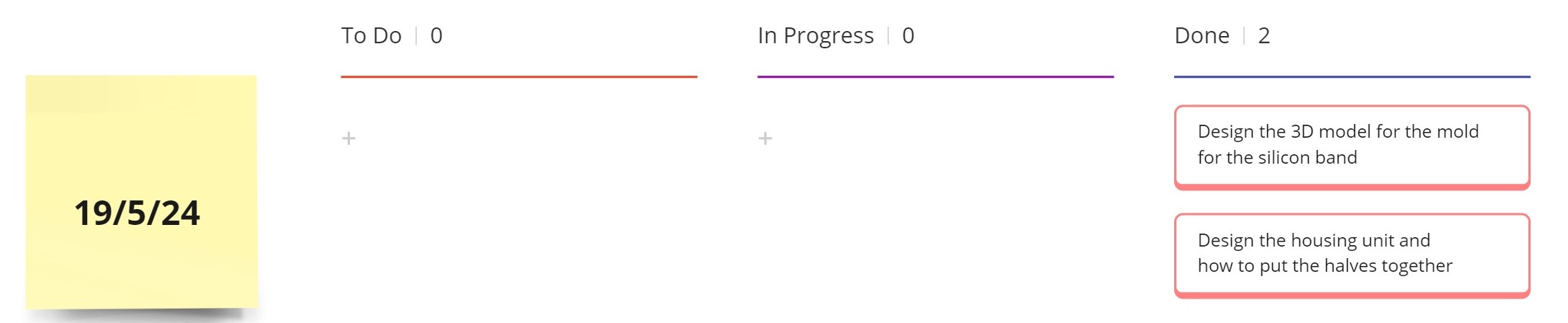
Schedule for the project
Production methods
Electronic Circuit and PCB Production:
3D Printing for Housing:
- Design the housing unit in Fusion360 such that the PCB fits well.
- Design the clips for the band
- 3D print the housing using materials like PLA or TPO.
- Print the clips of the silicon band.
Silicone Band Production with 3D-Printed Mold:
This method involves creating a mold using a 3D printer and then casting silicone into the mold.
Steps:
Interface:
B.O.M. - old one...revised one coming later
| COMPONENT | PACKAGE NAME | QUANTITY | COST |
|---|---|---|---|
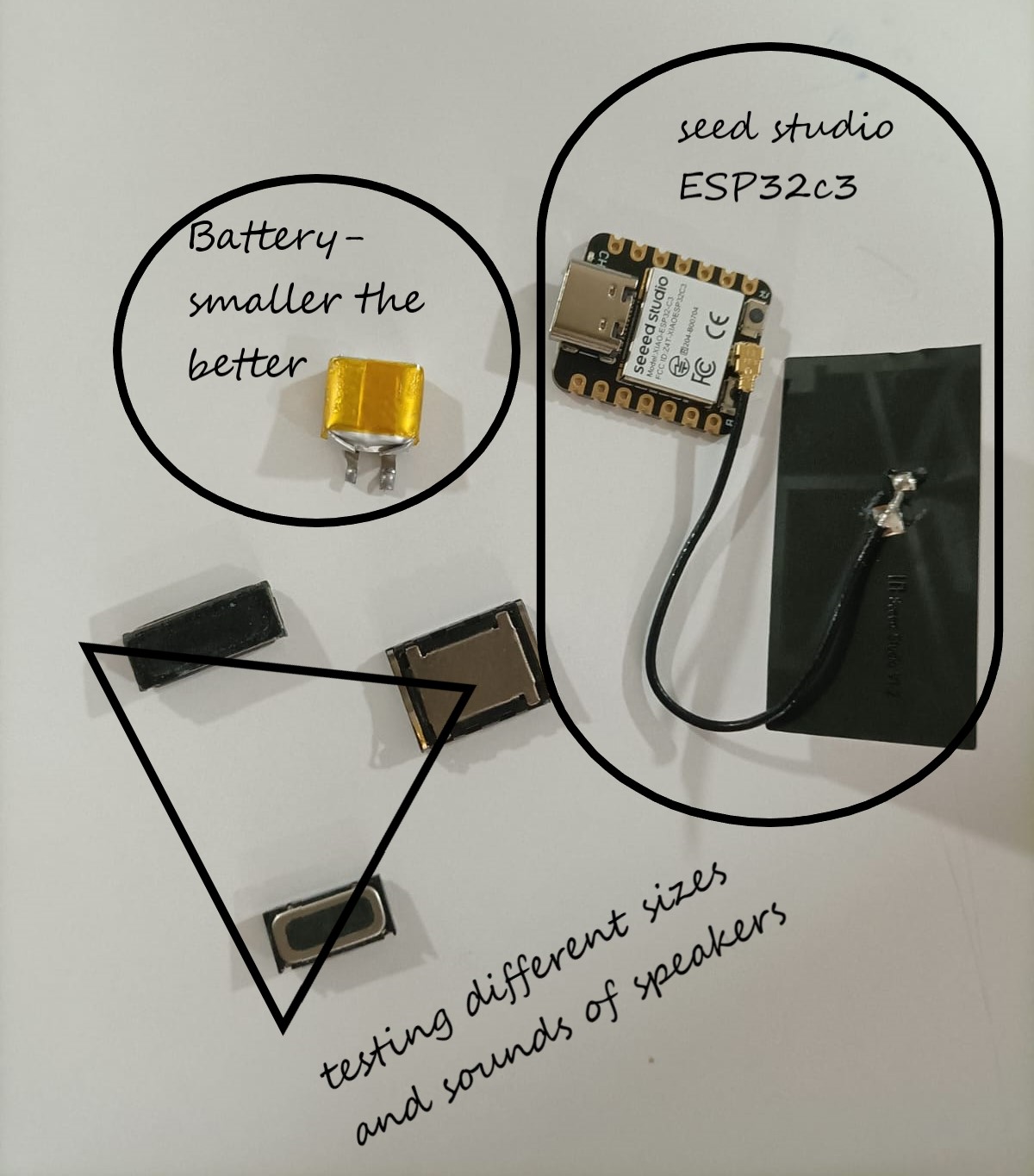
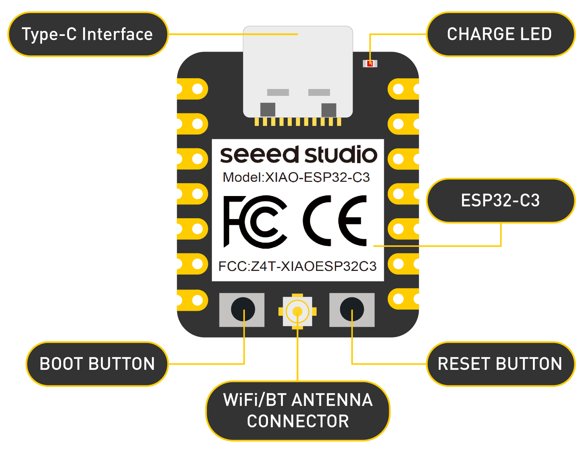
| Microcontroller | XIAO ESP32 | 1 | 699 |
| 3-axis accelerometer | ADXL 345 | 1 | 99 |
| Reminder Component-a | Neopixel LED | 1 | 359 |
| Reminder Component-b | Speaker | 1 | 42 |
| Capacitive sensors | Copper tape | 1 | 177 |
| Resistors | 1kohm,499ohm,10kohm | TBA | -- |
| Capacitors | 100nF,10mF,10nF | TBA | -- |
| Header Pins | 1X08,1x04,1x03 | 1 each | -- |
| Battery | Li rechargeable battery | 1 | 125 |
| PCB | Copper | 1 | -- |
| Connectors | Jumper wires | 4 | -- |
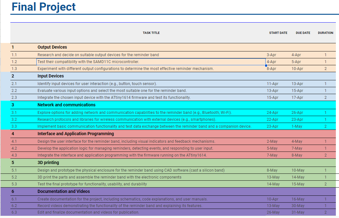
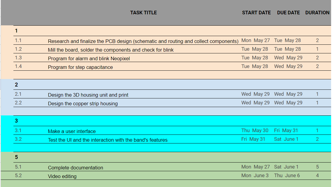
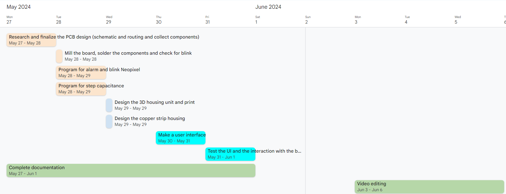
Project Schedule -old one, revised one coming later
| TASK TITLE | START DATE | DUE DATE | DURATION |
|---|---|---|---|
| 1 | |||
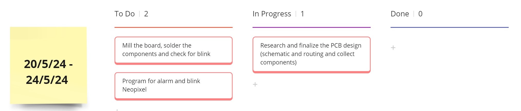
| 1.1 Research and finalize the PCB design (schematic and routing and collect components) | 20-May | 21-May | 2 |
| 1.2 Solder the components and check for blink | 21-May | 21-May | 1 |
| 1.3 Program for alarm and blink Neopixel | 22-May | 24-May | 3 |
| 2 | |||
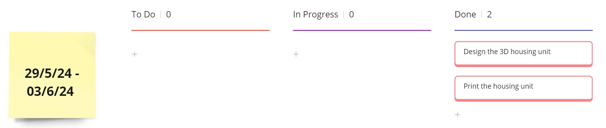
| 2.1 Design the 3D model for the mold for the silicon band | 19-May | 19-May | 1 |
| 2.2 Design the housing unit and how to put the halves together | 19-May | 19-May | 1 |
| 3 | |||
| 3.1 Make prototypes for the housing unit and cast the band - 3D print and test | 22-May | 24-May | 3 |
| 3.2 3D print housing unit | 24-May | 27-May | 4 |
| 4 | |||
| 4.1 Make a user interface | 28-May | 30-May | 3 |
| 4.2 Test the UI and the interaction with the band's features | 30-May | 1-Jun | 2 |
| 5 | |||
| 5.1 Complete documentation | 20-May | 3-Jun | 14 |
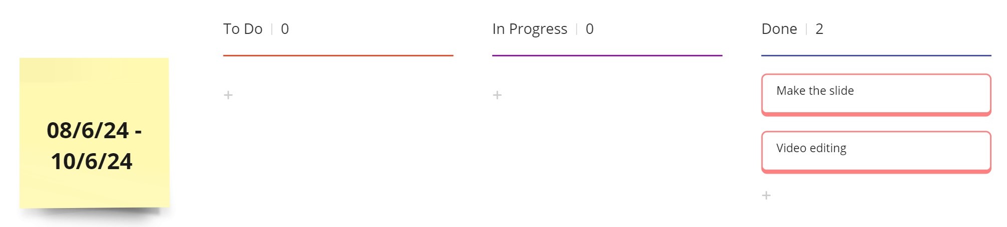
| 5.2 Video editing | 4-Jun | 5-Jun | 2 |
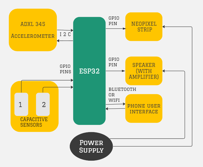
Block Diagram
Schematic
Components:- 1kΩ: For the I2C connection between the ESP32 and the accelerometer.
- 220Ω: For the NeoPixel data strip.
- 10kΩ: Pull-up resistors for the I2C data (SDA) and clock (SCL) lines.
- 100nF: Decoupling capacitor for the ESP32.
- 10µF: Filtering capacitor for the speaker output.
Connections
- VCC to 3.3V on Xiao ESP32
- GND to GND on Xiao ESP32
- SDA to SDA (I2C data line) on Xiao ESP32
- SCL to SCL (I2C clock line) on Xiao ESP32
- VCC to 3.3V on Xiao ESP32
- GND to GND on Xiao ESP32
- SIGNAL lines to specific GPIO pins on Xiao ESP32
- VCC to 5V power supply
- GND to GND on Xiao ESP32
- DIN to a GPIO pin on Xiao ESP32
- VCC to 5V power supply
- GND to GND on Xiao ESP32
- IN to a GPIO pin on Xiao ESP32
Points to remember:
Change of plans!!
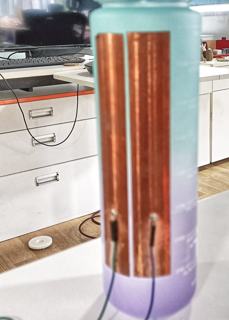
The idea was to use an accelerometer and detect any tilt in the bottle as an activity and to trigger reminders when there is inactivity. But my instructors, Jogin and Saheen suggested to test step response on the bottle with two copper strips. It worked! So, I changed my initial design concept to this: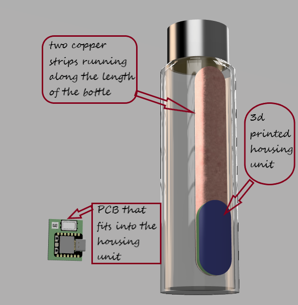 >
>
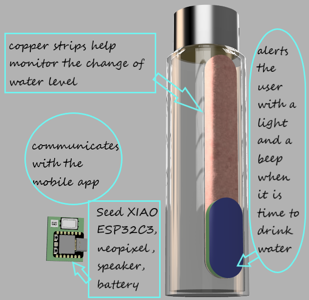
Now this means a new schedule, since there is no silicon band anymore.
Revised B.O.M.
| S.No. | COMPONENT | SOURCE | QUANTITY | COST |
|---|---|---|---|---|
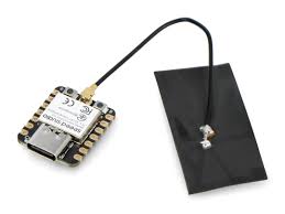
| 1 | Microcontroller-Xiao ESP32C3 | Fablab | 1 | 699 |
| 2 | LED RGB Clear | Fablab | 1 | 40 |
| 3 | Mobile Speaker | Local shop | 1 | 10 |
| 4 | Copper Tape | Fablab | 18cm x 3cm strip | - |
| 5 | Resistors | Fablab | 5 | 5 |
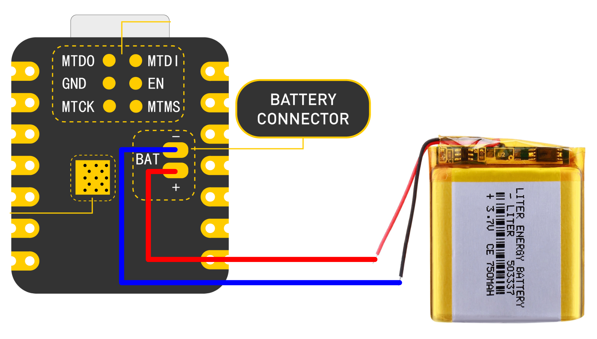
| 7 | Battery-LiPo LP251 320 40mAh | Local shop | 1 | 120 |
| Total(INR) | 874 | |||
| Total(USD) | 10.52 |

Testing step response
From Neil's input class Water has a high dielectric constant (about 80), compared to air (about 1). This means the presence of water between the plates significantly increases the capacitance.
      //
// hello.txrx.t1624.ino
//
// ATtiny1624 step response
//
// Neil Gershenfeld 11/14/21
//
// This work may be reproduced, modified, distributed,
// performed, and displayed for any purpose, but must
// acknowledge this project. Copyright is retained and
// must be preserved. The work is provided as is; no
// warranty is provided, and users accept all liability.
//

#define rxpin PIN_PA4 // receive pin
#define txpin PIN_PA5 // transmit pin
#define settle 100 // settle time
#define samples 100 // number of samples to accumulate

void setup() {
   Serial.begin(115200); // start serial
   pinMode(txpin,OUTPUT); // set transmit pin to output
   analogSampleDuration(5); // speed up ADC sampling
   analogReadResolution(12); // increase ADC resolution
   }

void loop() {
   int32_t up,down;
   up = down = 0;
   noInterrupts(); // disable interrupts while measuring
   for (int i = 0; i < samples; ++i) {
      digitalWriteFast(txpin,HIGH); // charge up
      up += analogRead(rxpin); // read
      delayMicroseconds(settle); //settle
      digitalWriteFast(txpin,LOW); // charge down
      down += analogRead(rxpin); // read
      delayMicroseconds(settle); // settle
      }
   interrupts(); // enable interrupts after measuring
   Serial.println(up-down); // send difference
   Serial.flush(); // finish communicating before measuring
   }
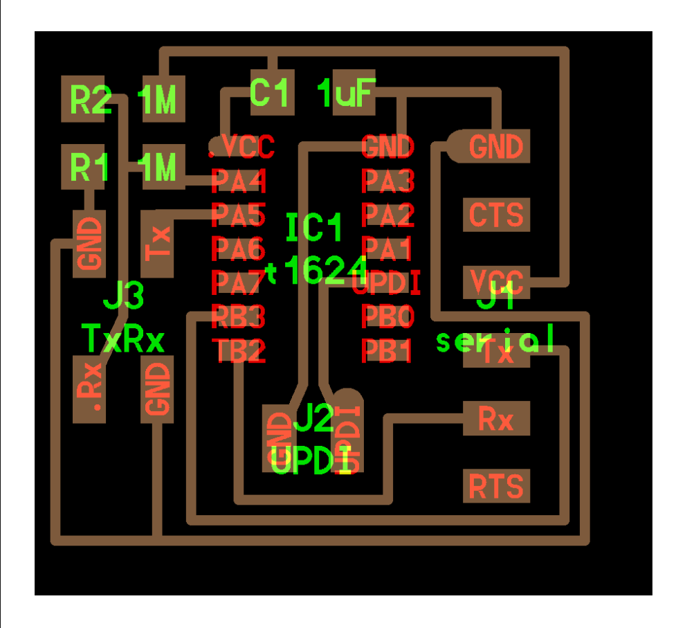
However, this is for an ATtiny1624 and I had a board with ATtiny1614 done in the Input week where I had given a pinout for doing this test with a 1Mohm resistor between the pins. Chatgpt modified the code for ATtiny1614 as below:
      //
// hello.txrx.t1614.ino
//
// ATtiny1614 step response
//
// Adapted by ChatGPT 05/23/24
//
// This work may be reproduced, modified, distributed,
// performed, and displayed for any purpose, but must
// acknowledge this project. Copyright is retained and
// must be preserved. The work is provided as is; no
// warranty is provided, and users accept all liability.
//

#define rxpin PIN_PA4 // receive pin (PA4 on ATtiny1614)
#define txpin PIN_PA5 // transmit pin (PA5 on ATtiny1614)
#define settle 100 // settle time
#define samples 100 // number of samples to accumulate

void setup() {
   Serial.begin(115200); // start serial
   pinMode(txpin, OUTPUT); // set transmit pin to output
   analogReadResolution(12); // increase ADC resolution
   }

void loop() {
   int32_t up, down;
   up = down = 0;
   noInterrupts(); // disable interrupts while measuring
   for (int i = 0; i < samples; ++i) {
      digitalWrite(txpin, HIGH); // charge up
      up += analogRead(rxpin); // read
      delayMicroseconds(settle); // settle
      digitalWrite(txpin, LOW); // charge down
      down += analogRead(rxpin); // read
      delayMicroseconds(settle); // settle
      }
   interrupts(); // enable interrupts after measuring
   Serial.println(up - down); // send difference
   Serial.flush(); // finish communicating before measuring
   }
From Chatgpt:
Explanation of Changes:
Pin Definitions: The pin definitions for rxpin and txpin are set to PIN_PA4 and PIN_PA5 respectively, as they are suitable for the ATtiny1614.
analogSampleDuration: The analogSampleDuration function is not directly supported in standard Arduino for ATtiny1614. Instead, ensuring proper ADC resolution is sufficient.
digitalWriteFast: Changed to digitalWrite since digitalWriteFast is not a standard function in all environments. You may need to use digitalWriteFast if you have the appropriate library; otherwise, digitalWrite should be adequate. Make sure you have the correct core and libraries for the ATtiny1614 when programming your board. You may need to use the MegaTinyCore for this purpose.
This is the error I got in Arduino:
In function 'check_valid_resolution', inlined from 'analogReadResolution.constprop' at C:\Users\DELL\AppData\Local\Arduino15\packages\megaTinyCore\hardware\megaavr\2.3.1\cores\megatinycore\wiring_analog.c:137:3, inlined from 'setup' at C:\Users\DELL\AppData\Local\Temp\.arduinoIDE-unsaved2024423-23584-1kq8zdi.11id\sketch_may23a\sketch_may23a.ino:23:24, inlined from 'main' at C:\Users\DELL\AppData\Local\Arduino15\packages\megaTinyCore\hardware\megaavr\2.3.1\cores\megatinycore\main.cpp:51:8: C:\Users\DELL\AppData\Local\Arduino15\packages\megaTinyCore\hardware\megaavr\2.3.1\cores\megatinycore\wiring_analog.c:124:7: error: call to 'badArg' declared with attribute error: badArg("analogReadResolution called with invalid argument - valid options are 8 or 10."); ^ lto-wrapper.exe: fatal error: C:\Users\DELL\AppData\Local\Arduino15\packages\DxCore\tools\avr-gcc\7.3.0-atmel3.6.1-azduino4b/bin/avr-gcc returned 1 exit status compilation terminated. c:/users/dell/appdata/local/arduino15/packages/dxcore/tools/avr-gcc/7.3.0-atmel3.6.1-azduino4b/bin/../lib/gcc/avr/7.3.0/../../../../avr/bin/ld.exe: error: lto-wrapper failed collect2.exe: error: ld returned 1 exit status exit status 1 Compilation error: exit status 1
And finally, the corrected code:
  //
// hello.txrx.t1614.ino
//
// ATtiny1614 step response
//
// Adapted by ChatGPT 05/23/24
//
// This work may be reproduced, modified, distributed,
// performed, and displayed for any purpose, but must
// acknowledge this project. Copyright is retained and
// must be preserved. The work is provided as is; no
// warranty is provided, and users accept all liability.
//

#define rxpin PIN_PA4 // receive pin (PA4 on ATtiny1614)
#define txpin PIN_PA5 // transmit pin (PA5 on ATtiny1614)
#define settle 100 // settle time
#define samples 100 // number of samples to accumulate

void setup() {
   Serial.begin(115200); // start serial
   pinMode(txpin, OUTPUT); // set transmit pin to output
   // Ensure ADC is configured correctly
   analogReadResolution(10); // set ADC resolution to 10 bits
   }

void loop() {
   int32_t up, down;
   up = down = 0;
   noInterrupts(); // disable interrupts while measuring
   for (int i = 0; i < samples; ++i) {
      digitalWrite(txpin, HIGH); // charge up
      up += analogRead(rxpin); // read
      delayMicroseconds(settle); // settle
      digitalWrite(txpin, LOW); // charge down
      down += analogRead(rxpin); // read
      delayMicroseconds(settle); // settle
      }
   interrupts(); // enable interrupts after measuring
   Serial.println(up - down); // send difference
   Serial.flush(); // finish communicating before measuring
   }
My instructor , Saheen changed the code as below to monitor the change in water level.
#define rxpin PIN_PA4 // receive pin (PA4 on ATtiny1614)
#define txpin PIN_PA6 // transmit pin (PA5 on ATtiny1614)
#define settle 100 // settle time
#define samples 100 // number of samples to accumulate
int32_t waterLevel =0;
void setup() {
   Serial.begin(115200); // start serial
   pinMode(txpin, OUTPUT); // set transmit pin to output
   // Ensure ADC is configured correctly
   analogReadResolution(10); // set ADC resolution to 10 bits
   }

void loop() {
   int32_t up, down;
   up = down = 0;
   noInterrupts(); // disable interrupts while measuring
   for (int i = 0; i < samples; ++i) {
      digitalWrite(txpin, HIGH); // charge up
      up += analogRead(rxpin); // read
      delayMicroseconds(settle); // settle
      digitalWrite(txpin, LOW); // charge down
      down += analogRead(rxpin); // read
      delayMicroseconds(settle); // settle
      }
   interrupts(); // enable interrupts after measuring
  //  Serial.println(up - down); // send difference
   int32_t diffrence = up-down;
   Serial.print(diffrence);
   waterLevel = map(diffrence,40500,72000,0,100);
   Serial.print("\t");
   Serial.print(waterLevel);
   Serial.println("%");
   Serial.flush(); // finish communicating before measuring
   }
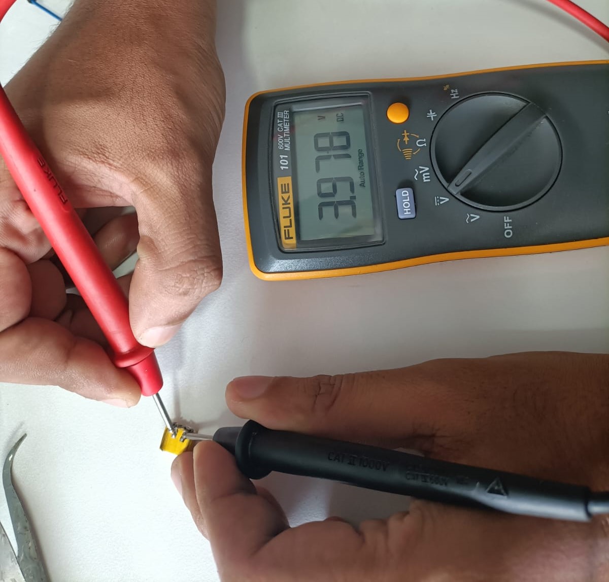
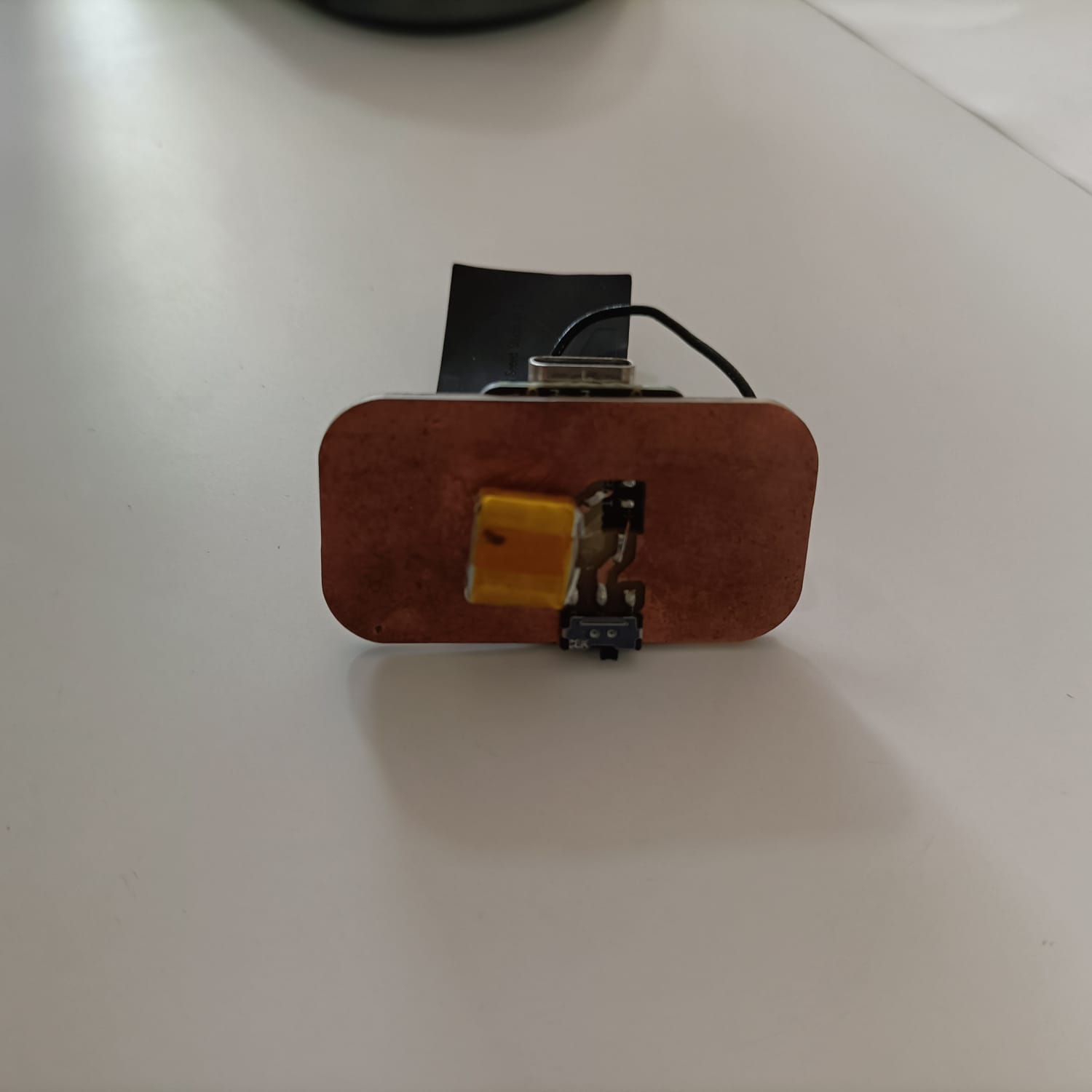
Testing the battery and speaker
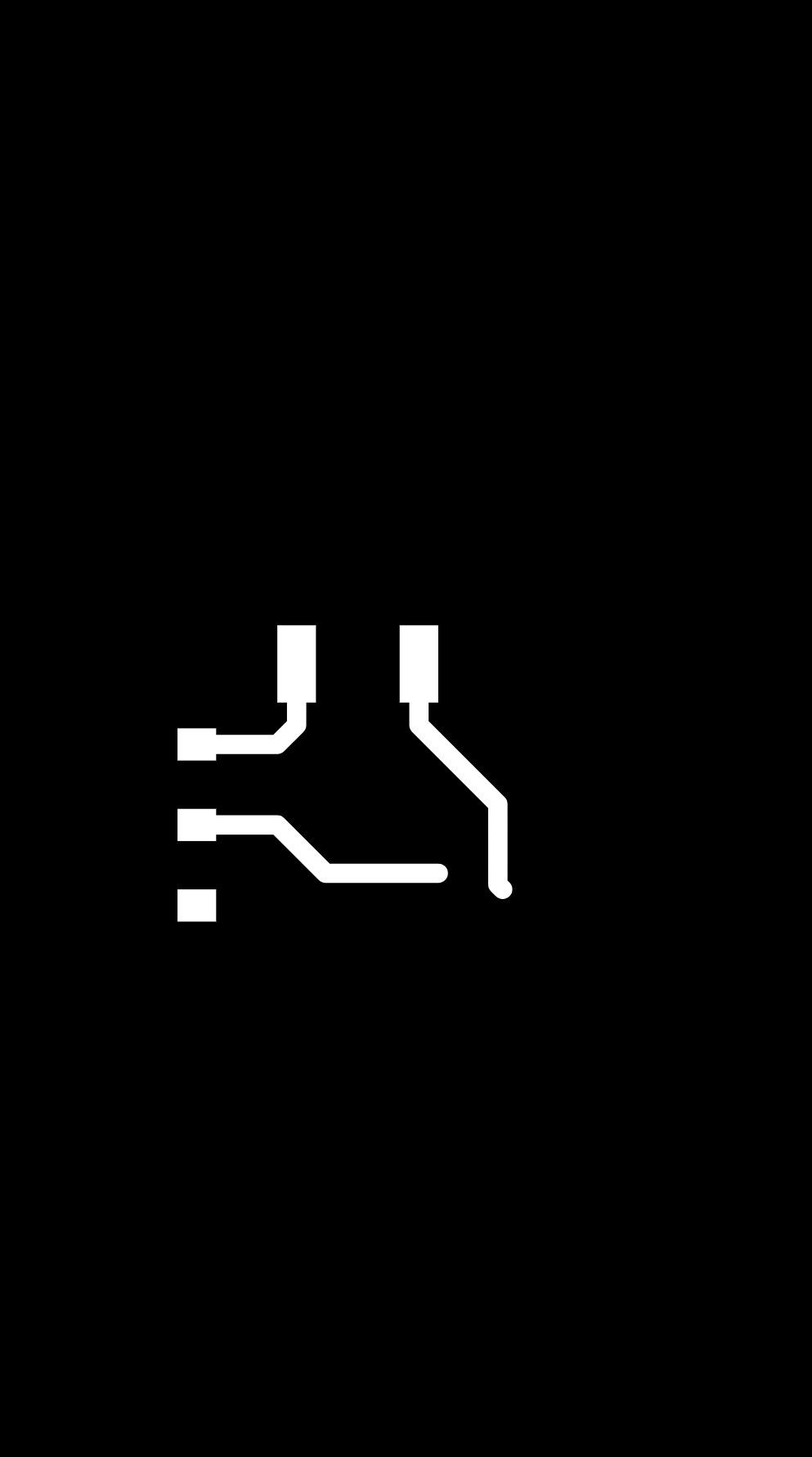
PCB design
Schematic
The schematic was done in kiCad.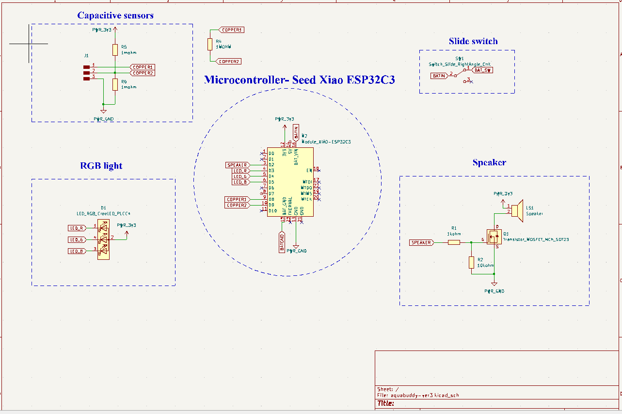
Initially, I wanted to use a neopixel. The voltage from my battery is showing as 3.98V, which is insufficient for powering a Neopixel that requires around 4.5V, rendering it unsuitable for use with my board. So, I used a RGB instead.
In Neil's notes, he has given two circuits for RP2040 and t1624. I tested using Attiny1614 using RP2040's circuit. I will have to find out which works for ESP32. I have given options for both in my board.
.png)
.png)
3D representation
To see it in 3D,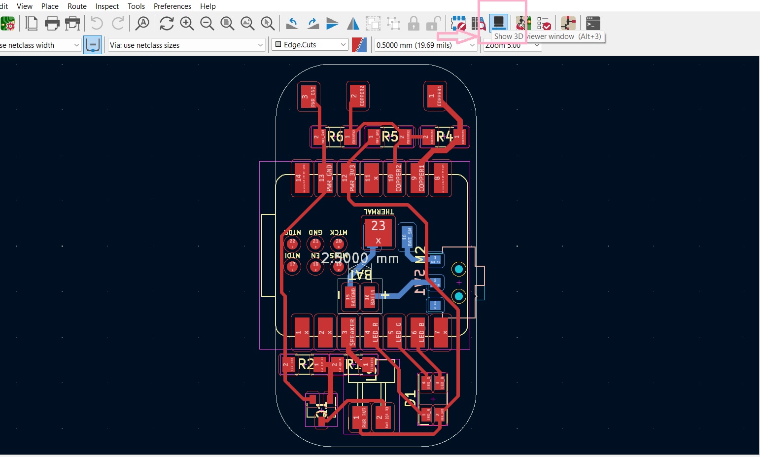
.png)
.png)
Designing the housing unit
The housing unit seems like a very small part of the project but I realised that it was a very vital part. There was lots of attention to detail required at this required for this.When designing the housing unit,these points had to be remembered:
.png)
.png)
Try 1
This was the first trial. However, here the speaker didn't have a closed chamber. The chamber has to be closed so that the sound can come clearly outside..jpg)
.jpg)
Try 2 and Try 3
In the second trial, the speaker still wasn't fitting perfectly and the provision for the copper tape was on the side which wasn't practical either. Also, the ESP32 was jutting out and not fitting well. In the third trial, the location for the copper wires to come into the PCB was provided correctly and the speaker chamber was correct..jpg)
.jpg)
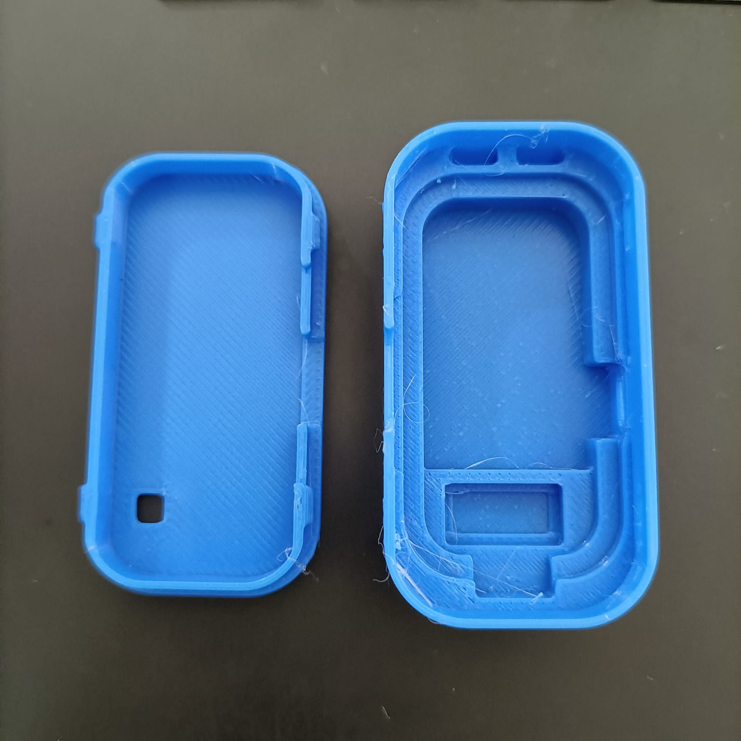
Try 4 and the final!
In the fourth trial, I used PETG and it failed. Finally, trial 4 fit well for the components of the PCB..jpg)
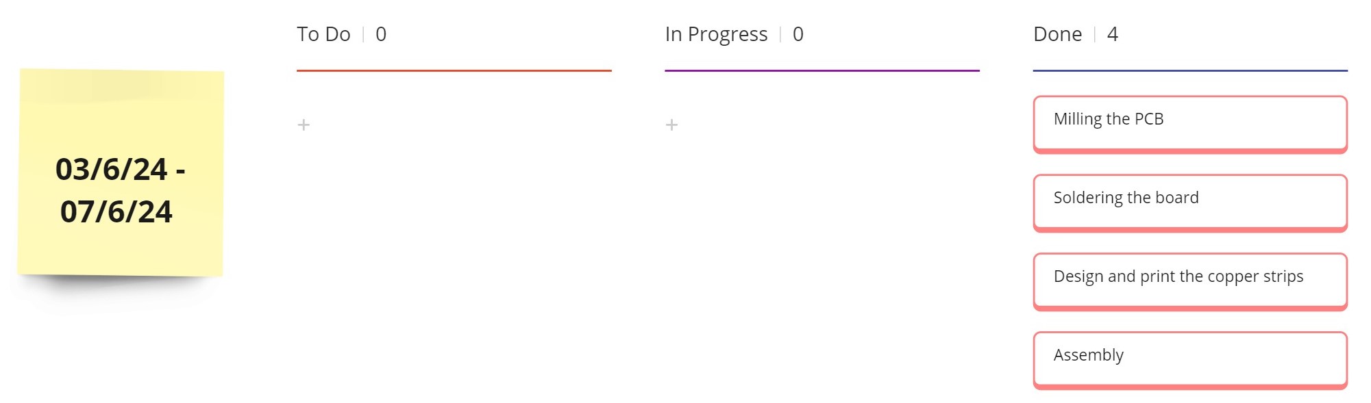
Milling the board
This was the first time I was doing a two-sided PCB. Using, https://gerber2png.fablabkerala.in/ it was easier. The traces and the outline on the topside are shown below:.png)
.png)
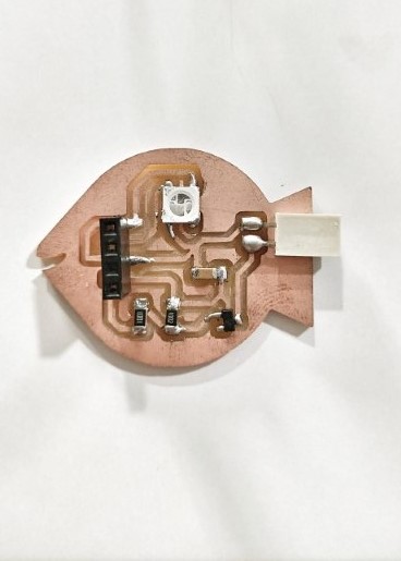
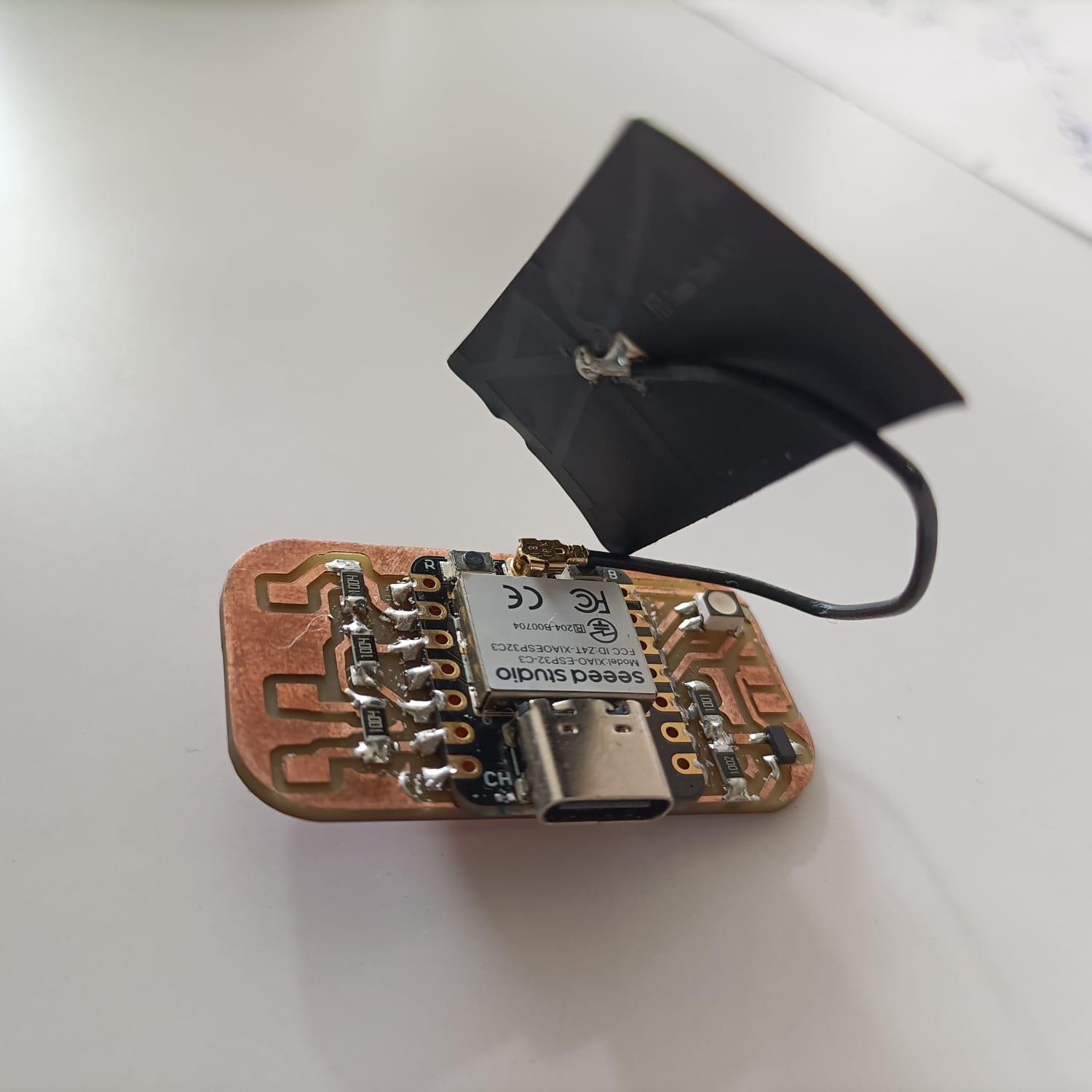
Soldered PCB
I collected the remaining components from the Fab inventory.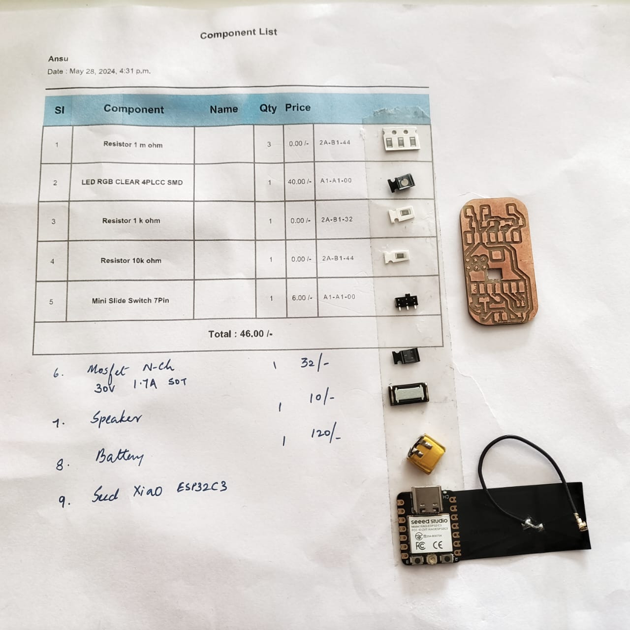 A stop motion video of the PCB being soldered. I find it difficult to solder small components. Saheen helped me do
the soldering.
A stop motion video of the PCB being soldered. I find it difficult to solder small components. Saheen helped me do
the soldering.Here is the front side and back side of the soldered PCB.
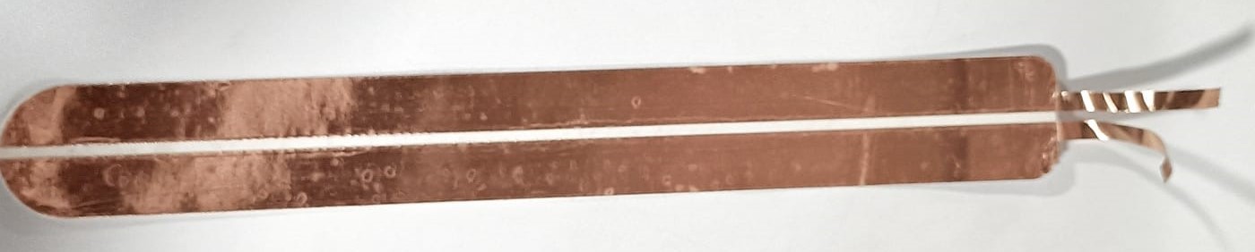
Copper strips
The copper strips were designed in fusion and exported in dxf to be cut in the Zund. For more details about Zund, refer Computer controlled CuttingHere is how the copper strips were cut out in Zund.
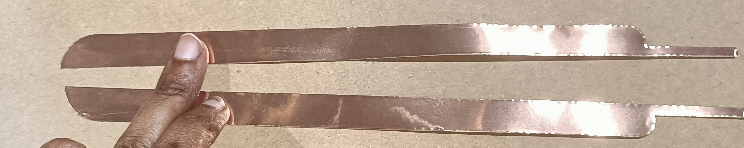
Here, a sticker is placed behind the copper strips so that the strip used can be cut, the sticker peeled and stuck on any bottle.
Arranging the box
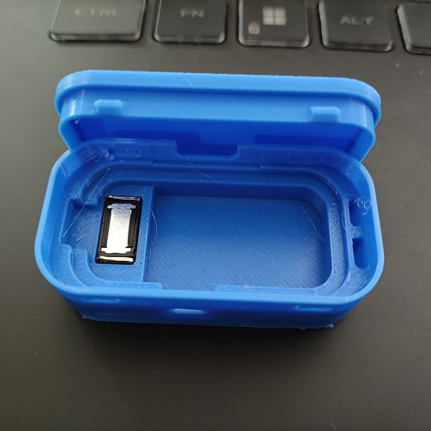
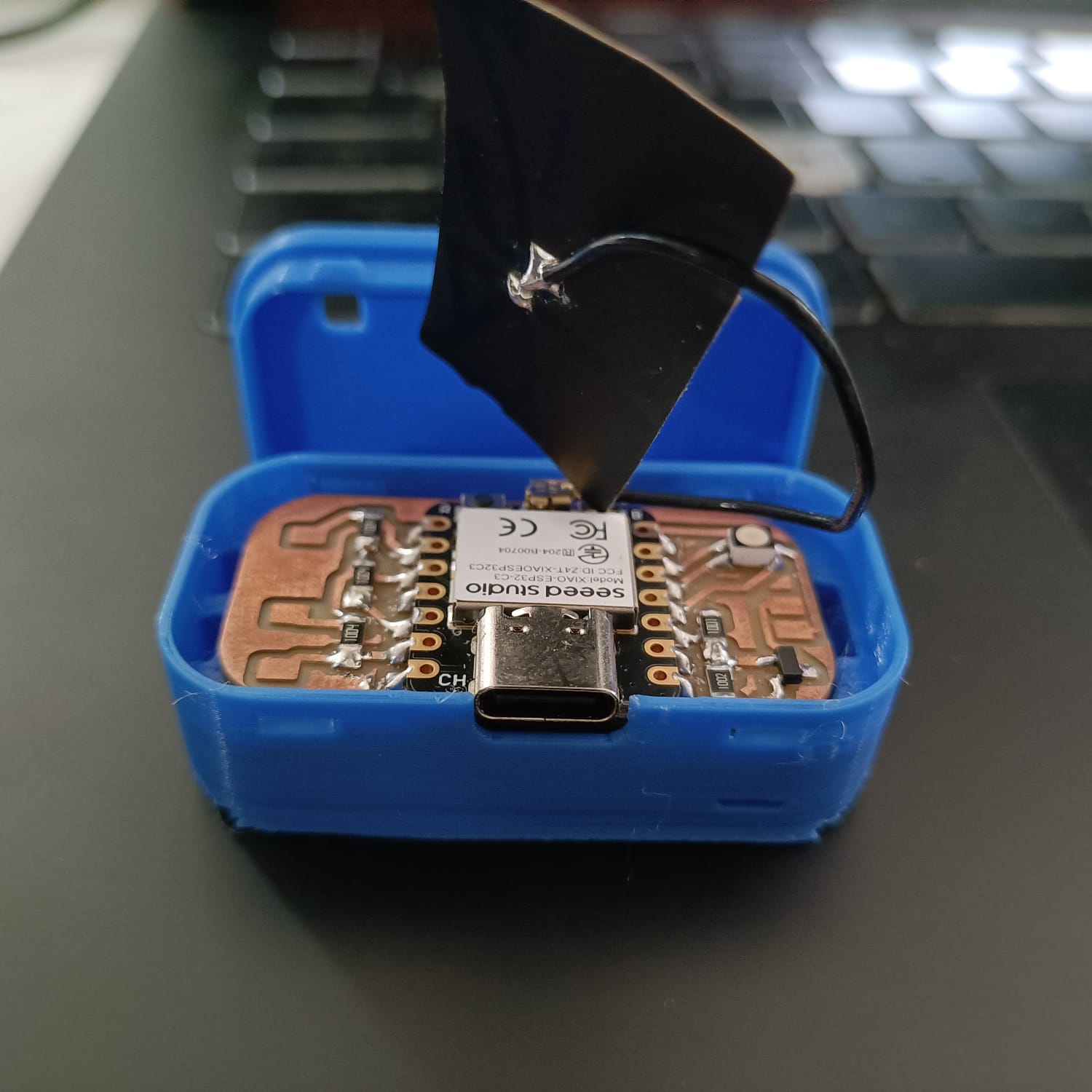
Assembly
This video shows the soldered PCB and the assembly of the Aqua Buddy.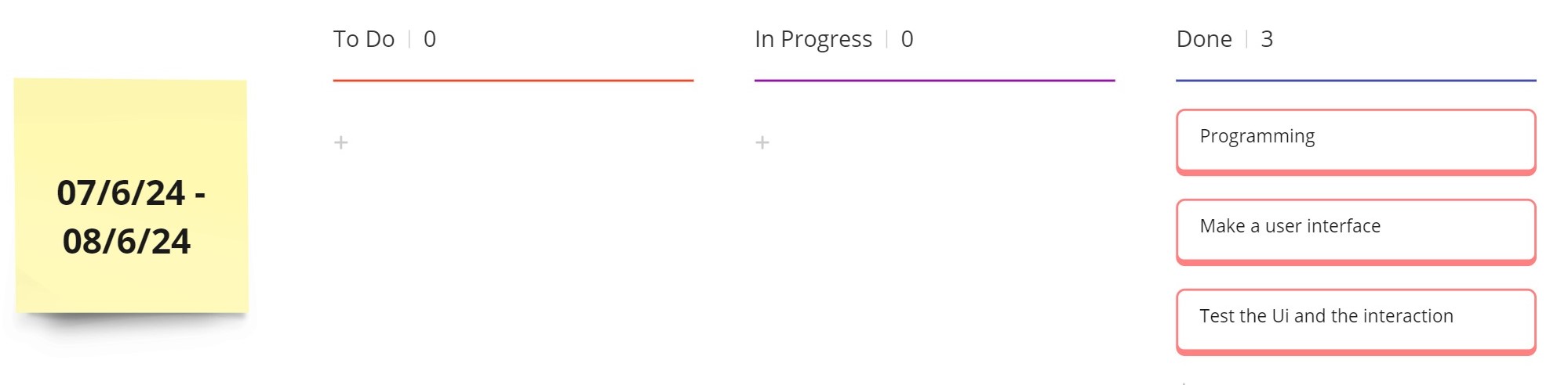
Programming
#include < WiFi.h>
#include < FirebaseESP32.h>
#include "time.h"
#define DATA_PATH "/live/data/waterLevel"
bool taken = false;
#define NOTE_C4 261 // Define the frequency for note C4 (Do)
#define NOTE_D4 294 // Define the frequency for note D4 (Re)
#define NOTE_E4 330 // Define the frequency for note E4 (Mi)
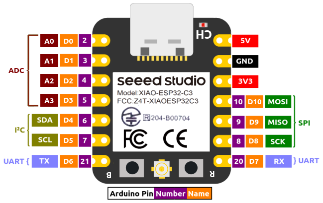
#define SPEAKER_PIN D2 // Define the pin to which the speaker is connected
#define rxpin D0 // receive pin (D0 on XIAO ESP32-C3)
#define txpin D8 // transmit pin (D8 on XIAO ESP32-C3)
#define settle 100 // settle time
#define samples 100 // number of samples to accumulate
int32_t waterLevel = 0;
int32_t difference = 0;
//Wifi Confifg
#define WIFI_SSID "FabGuest" // your wifi SSID
#define WIFI_PASSWORD "4fabGUEST" // your Wiif Password
//Firebase config
#define FIREBASE_HOST "https://aqua-buddy-3d5cb-default-rtdb.firebaseio.com/" // firebase realtimeDB api url https://project-name.firebaseio.com/
#define FIREBASE_AUTH "AIzaSyCoLwSZiBMunNANLwR6ctUlQLtbasnj9OM" // API key
FirebaseData fbdo;
FirebaseJson json;
FirebaseJson json2;
// NTP Server config
// const char *ntpServer = "pool.ntp.org";
// const long gmtOffset_sec = 5 * 3600 + 30 * 60; // UTC+5:30
// const int daylightOffset_sec = 0; // India does not observe daylight saving time
// int timestamp;
void setup() {
Serial.begin(115200);
WiFi.begin(WIFI_SSID, WIFI_PASSWORD);
while (WiFi.status() != WL_CONNECTED) {
delay(1000);
Serial.println("Connecting to WiFi...");
}
Serial.println("Connected to WiFi");
// Initialize Firebase
Firebase.begin(FIREBASE_HOST, FIREBASE_AUTH);
// configTime(gmtOffset_sec, daylightOffset_sec, ntpServer);
// timestamp = printLocalTime(1);
pinMode(txpin, OUTPUT); // set transmit pin to output
analogReadResolution(12); // set ADC resolution to 12 bits (ESP32)
pinMode(SPEAKER_PIN, OUTPUT); // Set the speaker pin as an output
pinMode(D4, OUTPUT);
}
void loop() {
int senserData = waterData();
if (senserData>=100){senserData = 100;}
if (Firebase.setInt(fbdo, DATA_PATH, senserData)) {
} else {
Serial.println("Failed to set data");
Serial.println("Reason: " + fbdo.errorReason());
}
if (Firebase.setInt(fbdo, "/live/data/value", difference)) {
} else {
Serial.println("Failed to set data");
Serial.println("Reason: " + fbdo.errorReason());
}
delay(500);
digitalWrite(D4, HIGH); // turn the LED on (HIGH is the voltage level)
delay(100);
digitalWrite(D4, LOW); // turn the LED on (HIGH is the voltage level)
}
int waterData(){
int32_t up, down;
up = down = 0;
noInterrupts(); // disable interrupts while measuring
for (int i = 0; i < samples; ++i) {
digitalWrite(txpin, HIGH); // charge up
up += analogRead(rxpin); // read
delayMicroseconds(settle); // settle
digitalWrite(txpin, LOW); // charge down
down += analogRead(rxpin); // read
delayMicroseconds(settle); // settle
}
interrupts(); // enable interrupts after measuring
difference = up - down;
// Serial.print(difference);
// waterLevel = map(difference, 60840, 239645, 0, 100);
waterLevel = map(difference, 63083, 147481, 0, 100);
// Serial.print("\t");
Serial.print(waterLevel);
// Serial.println("%");
// Serial.flush(); // finish communicating before measuring
return waterLevel;
}
In the above program,
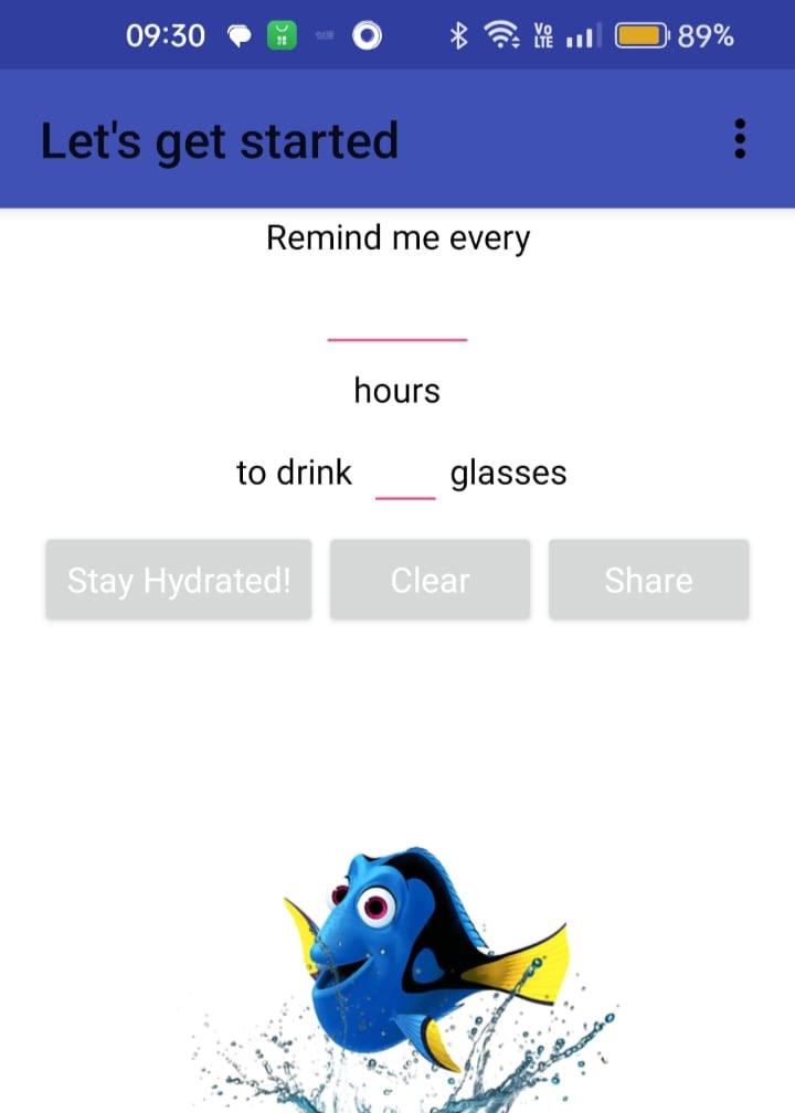
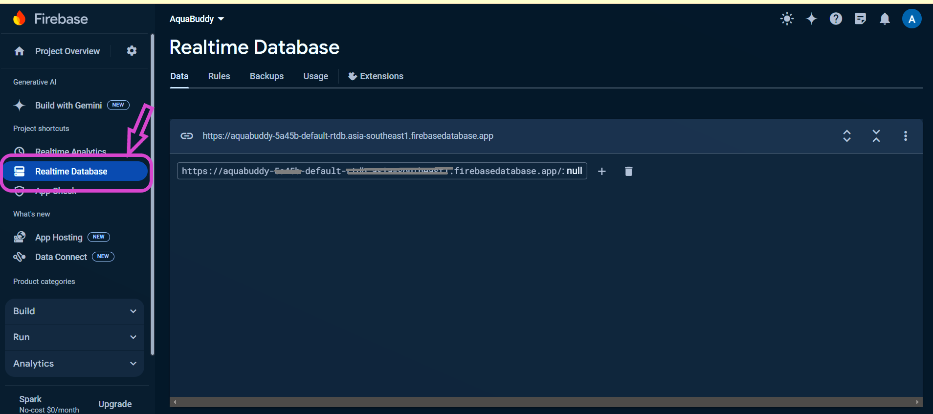
User Interface
The app for the AquaBuddy Band is designed to help you stay hydrated effortlessly. You can customize your hydration goals by inputting the number of glasses of water you intend to drink each day and set the desired intervals for reminders. Based on your settings, the app sends timely light and sound alerts to the AquaBuddy stuck on your bottle, ensuring you never miss a reminder. Additionally, the app displays the percentage of water you have consumed throughout the day and helps you locate your bottle when needed. With its user-friendly interface and seamless integration, staying hydrated has never been simpler or more engaging.Midlaj helped me to make the webserial app. A web serial app that communicates between the board and a Firebase database typically involves three main components:
- Create a Firebase project and configure the Realtime Database.
- Arduino code sends sensor data via serial and listens for commands from the web app.
- Initializes Firebase and sets up functions to read/write data.
- Uses the Web Serial API to connect to the microcontroller, read sensor data, and send commands.
- Sensor data is displayed on the webpage and stored in Firebase.
- Commands from Firebase are sent to the microcontroller.
Running the last mile!!
This is the screen on the laptop and the phone while calibrating the bottle.Here, is the screen recording of the app.
Once, the alerts are received, it's time to hydrate!
A message to remember....
Be reminded, Stay hydrated!
Design Files
PCB FilesPCB design -Schematic, gerber
PNG files
Housing Unit
Fusion (.f3z) design
Copper strips
Template used in zund
Program -Arduino IDE
Water level
Step response
User Interface
Aqua Buddy- App
Acknowledgment
I am deeply grateful for the invaluable guidance and support of my instructors throughout this project.I would like to express my heartfelt thanks to Jogin for his expert guidance in the design of the housing unit. His insights and suggestions were crucial in shaping the final design.
A special thanks to Saheen for his assistance with soldering and programming. His technical expertise and patience greatly contributed to the successful completion of the project.
I am also thankful to Midlaj for his help in developing the app. His proficiency and dedication were instrumental in bringing the app to life.
I would like to acknowledge Mufeed for his creative help in designing the fish to be placed over the housing unit. His artistic skills added a unique touch to the project.
Lastly, I am immensely proud of and grateful to my son, Jaiden, for learning Blender to assist me with the design. His enthusiasm and willingness to help made this journey even more special.
I also want to extend my heartfelt gratitude to my fabmates for the times we spent learning together, their company, the jokes we shared, the friendly teasing, and the enjoyable moments we shared over meals. The camaraderie, laughter, and support from each of you made this experience memorable and enriching.
License
Fab Academy by Ansu Thomas is licensed under Creative Commons
Attribution-NonCommercial-ShareAlike 4.0 International