Electronics Production
The assignments for this week:
- Group assignment : Characterize the design rules for your in-house PCB production process send a PCB out to a board house
- Individual assignment:
- make and test a microcontroller development board
Group assignment:
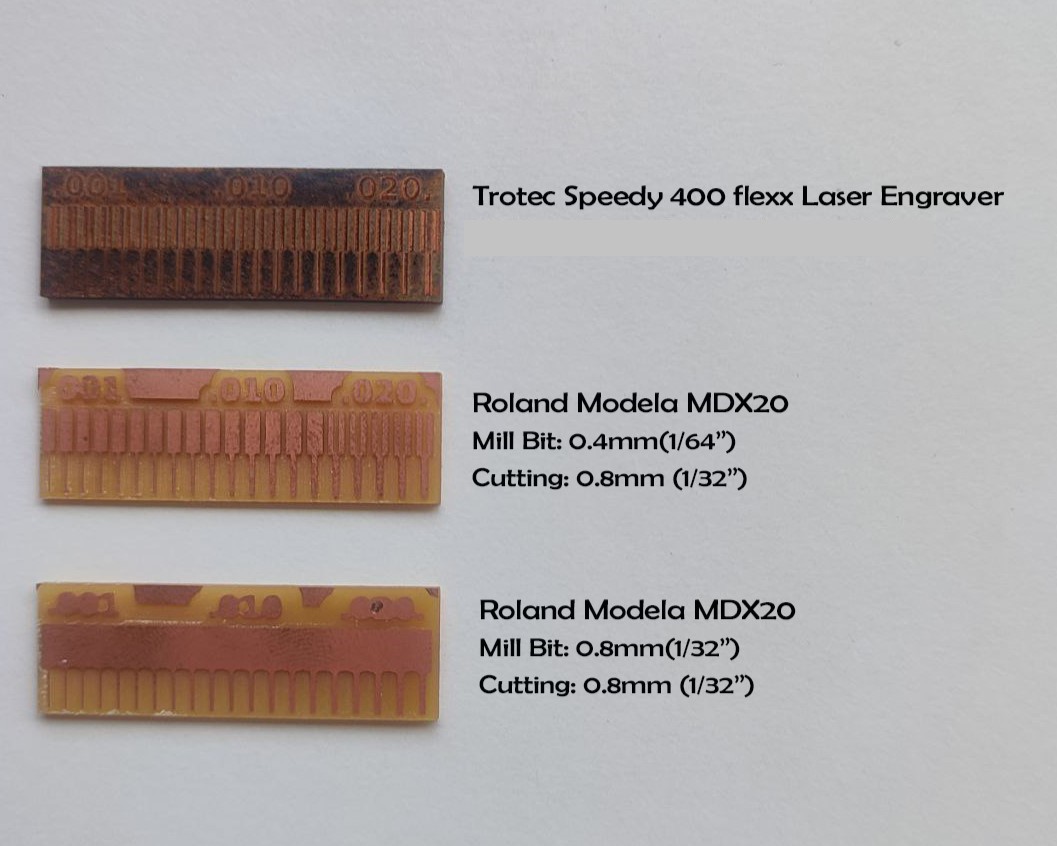
Characterize design rules for the in-house PCB production
What is a PCB?
Since this was a completely new topic for me, I thought of finding out
what a PCB does exactly.I found this video in youtube very interesting and it gave
me a clear idea of the basics of a PCB.
What are PCBs?How do PCBs work?
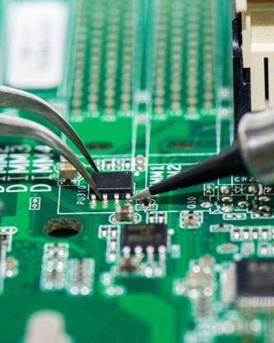
A PCB or a 'Printed Circuit Board' is a crucial component in electronic
devices. It has a complex network of metallic pathways which serve as
electrical pathways that facilitate the flow of current between different
components on the board.
Embedded within the board are various electronic components such as resistors, capacitors, transistors,
and integrated circuits (ICs). Each component plays a specific role
in the overall functionality of the device, and they are
strategically placed and soldered onto the PCB according to the
circuit design.
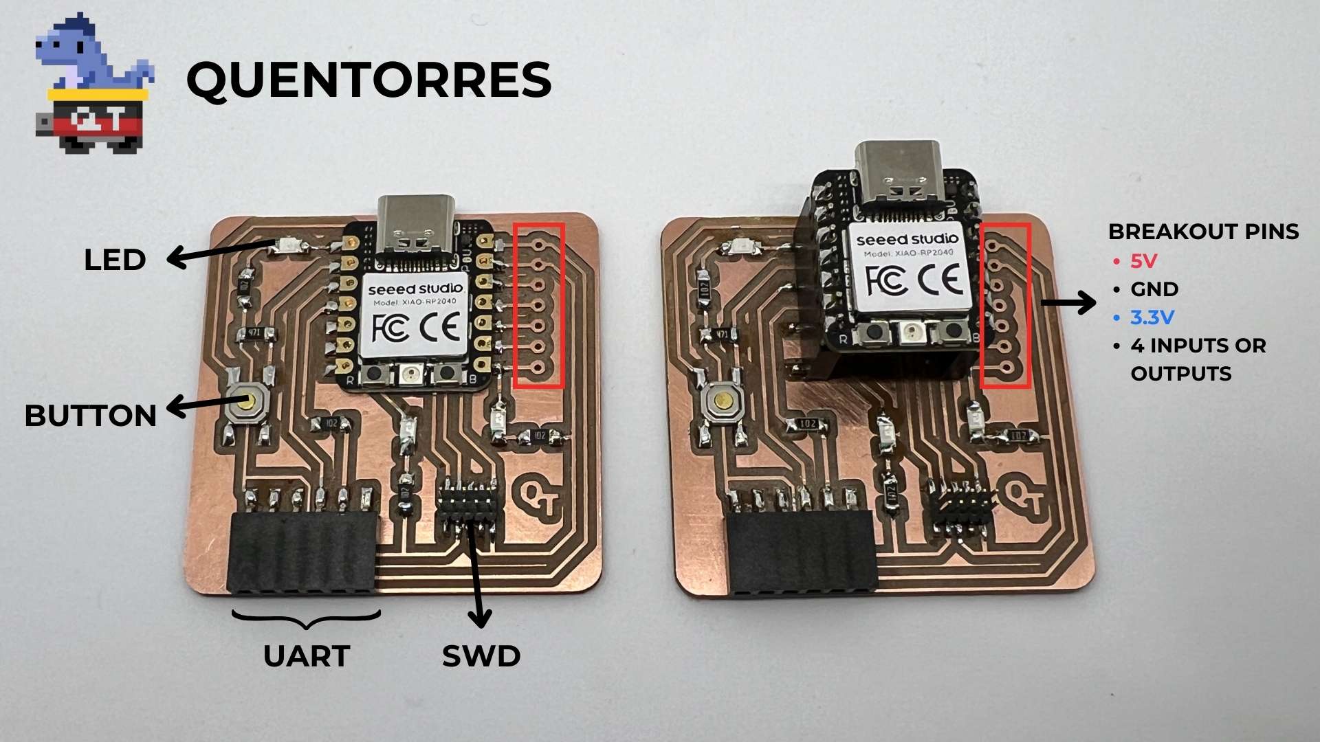
About Quentorres
The Quentorres,developed at the 2024 Instructors Bootcamp held in León is a board that can program the new AVR Series 1 and 2. It also has a button and an LED to learn to program in C, Rust, Go, Micropython etc. It has breakout pins to connect other external elements. It was created by Quentin Bolsée and redesigned by Adrián Torres. The perfect combination of a programmer to rule them all and a hello board to learn to program.
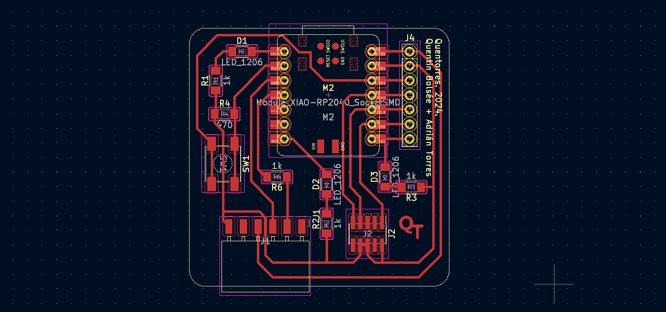
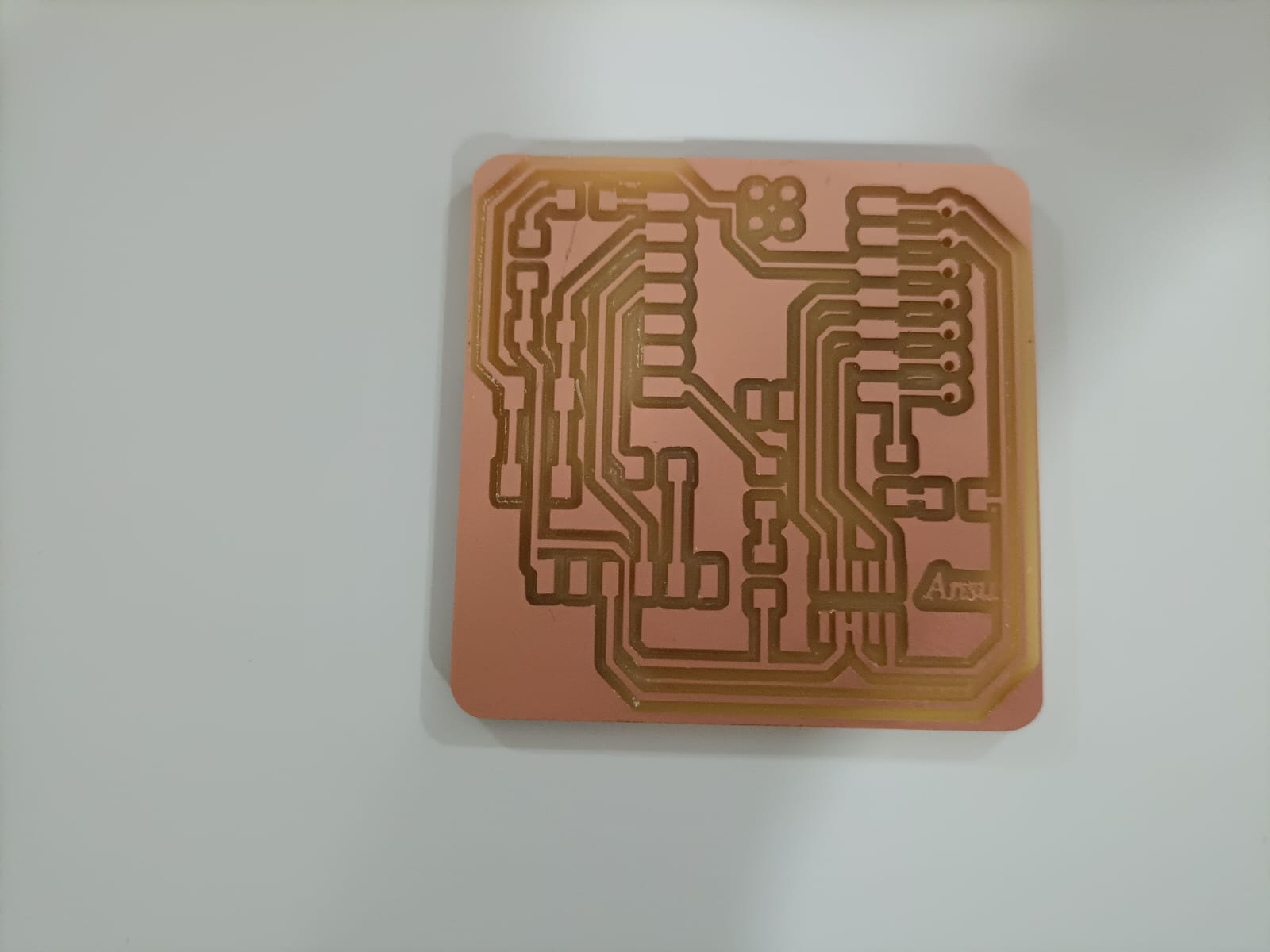
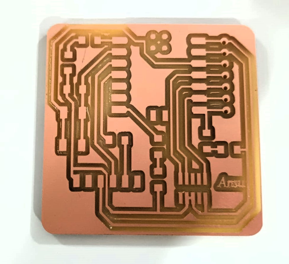
Tracing and milling the PCB using the Modela
The Roland Modela is a milling machine which can be used to trace and mill the pcb.
.jpg)
Here are the steps i followed:
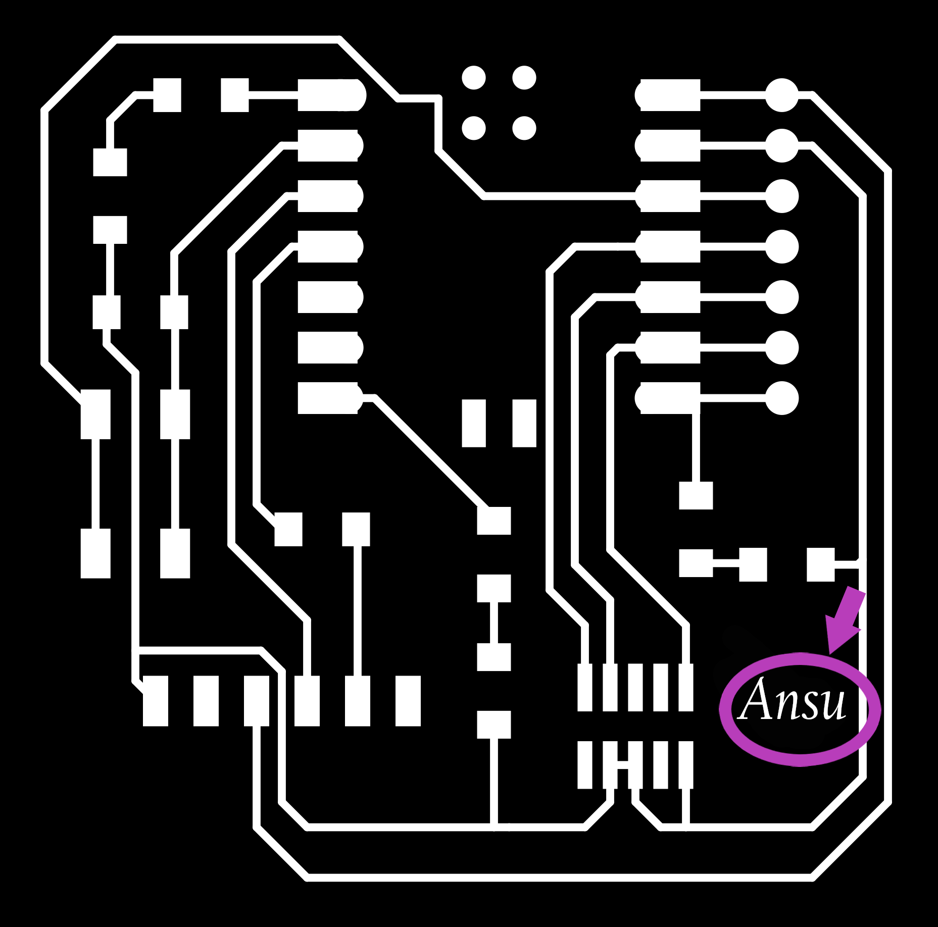
- Initially, I downloaded the trace cut png files provided by the Academy. I opened it in Gimp and customised the text 'QT' to 'Ansu'. I, then, exported it and uploaded it in Mods.
- Let's begin by preparing the PCB for milling. To ensure that the PCB remains in place throughout the
milling process,it is stuck onto a sacrificial copper plate with a double-sided tape. We have to remove any residue tape before placing
the new PCB.
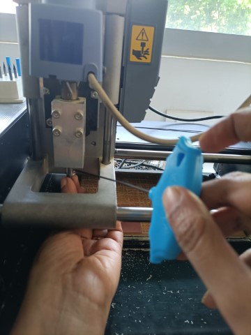
- The next step is to get familiar and set up the machine. After switching on the machine, the milling head moves to the orgin position. Press, 'View' button, so that the plate comes forward and we can change the bit.
- Since, we
will be milling the traces first, we can use the 0.4mm bit. It is very delicate
and should be handled very carefully or it would break.
.jpg)
- Use the Allen key.Be very cautious and always hold the bit while screwing or unscrewing it.
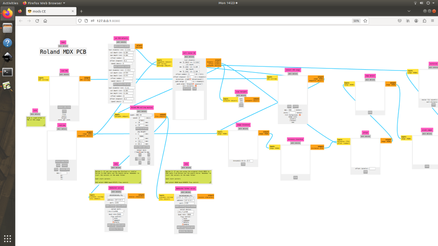
- Next, start Mods and open a terminal. Type 'bash start servers', right click anywhere
and choose programs. Then, click PCB under MDX mill.
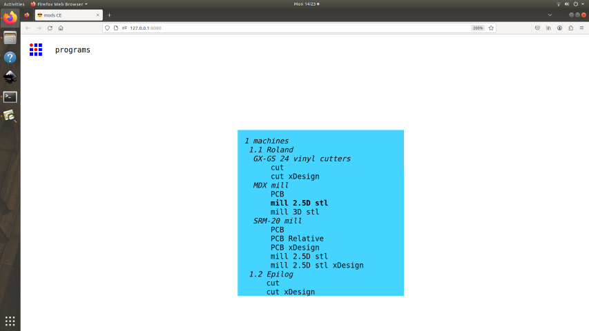
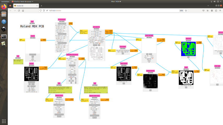
- When the web of connected modules opens, upload the png file.
- Set the PCB defaults, mill traces- 1/64 and for mill outline - 1/32
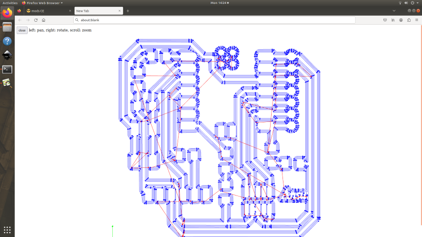
- In the mill raster, click 'calculate' and you can view the path.
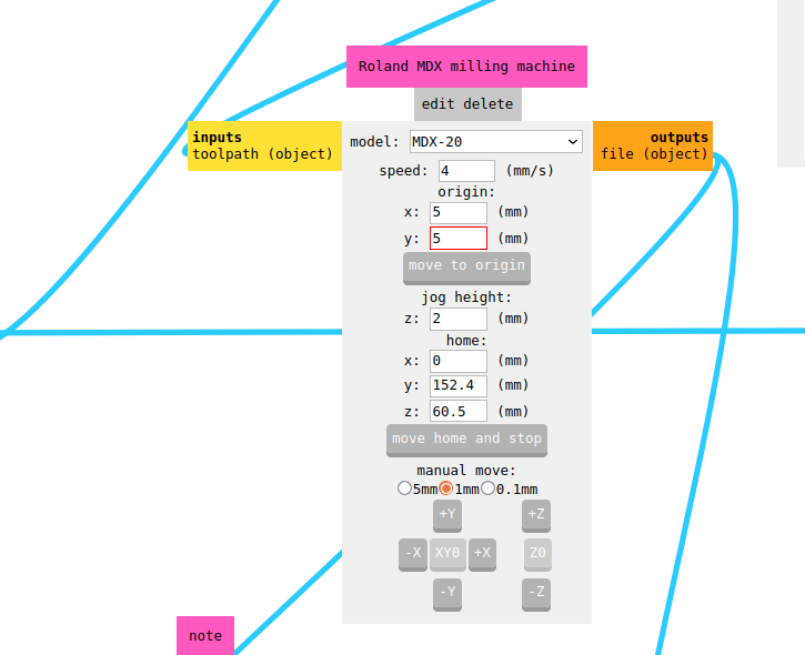
- Set the orgin. In this case it was x=5 and y=5.
- Ensure the bit is tightened before sending the file
- Once the traces are done, the files for the outline can be done after changing the bit to 0.8mm .
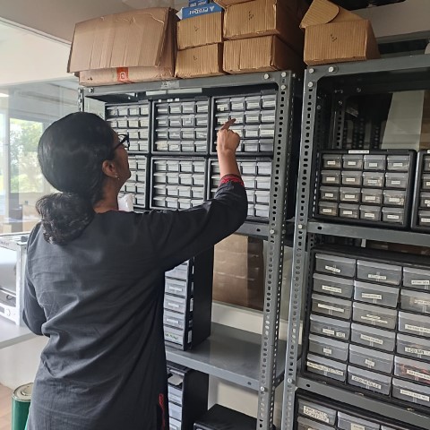
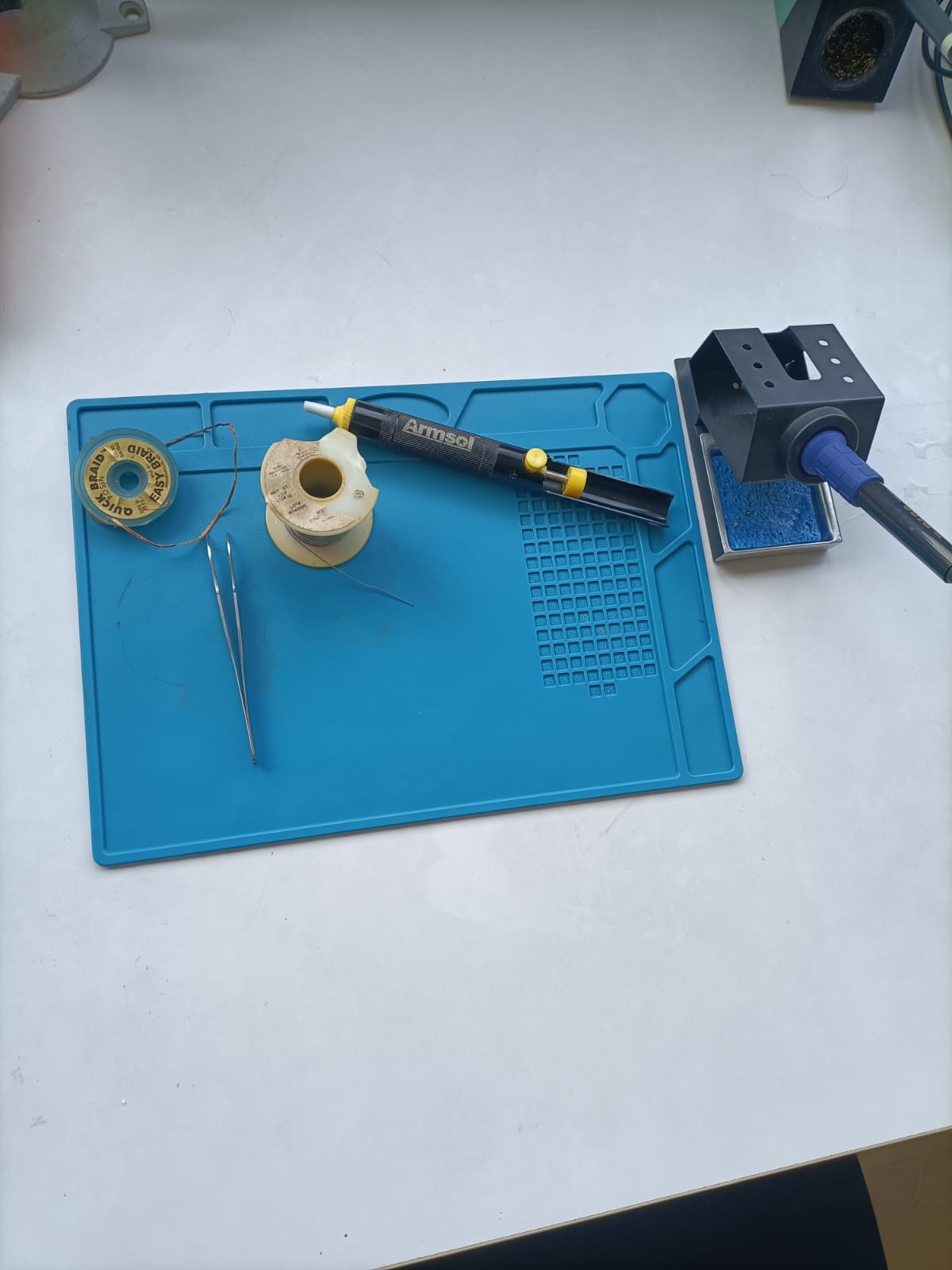
- I began by gathering all the necessary components. I laid out the components on the table, carefully comparing them to the circuit diagram to ensure I had everything I needed.
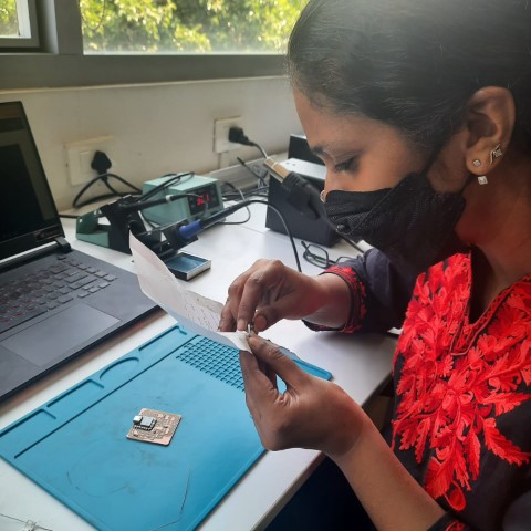
- I ensured that the PCB is clean and free of any contaminants or residues that could interfere with soldering.
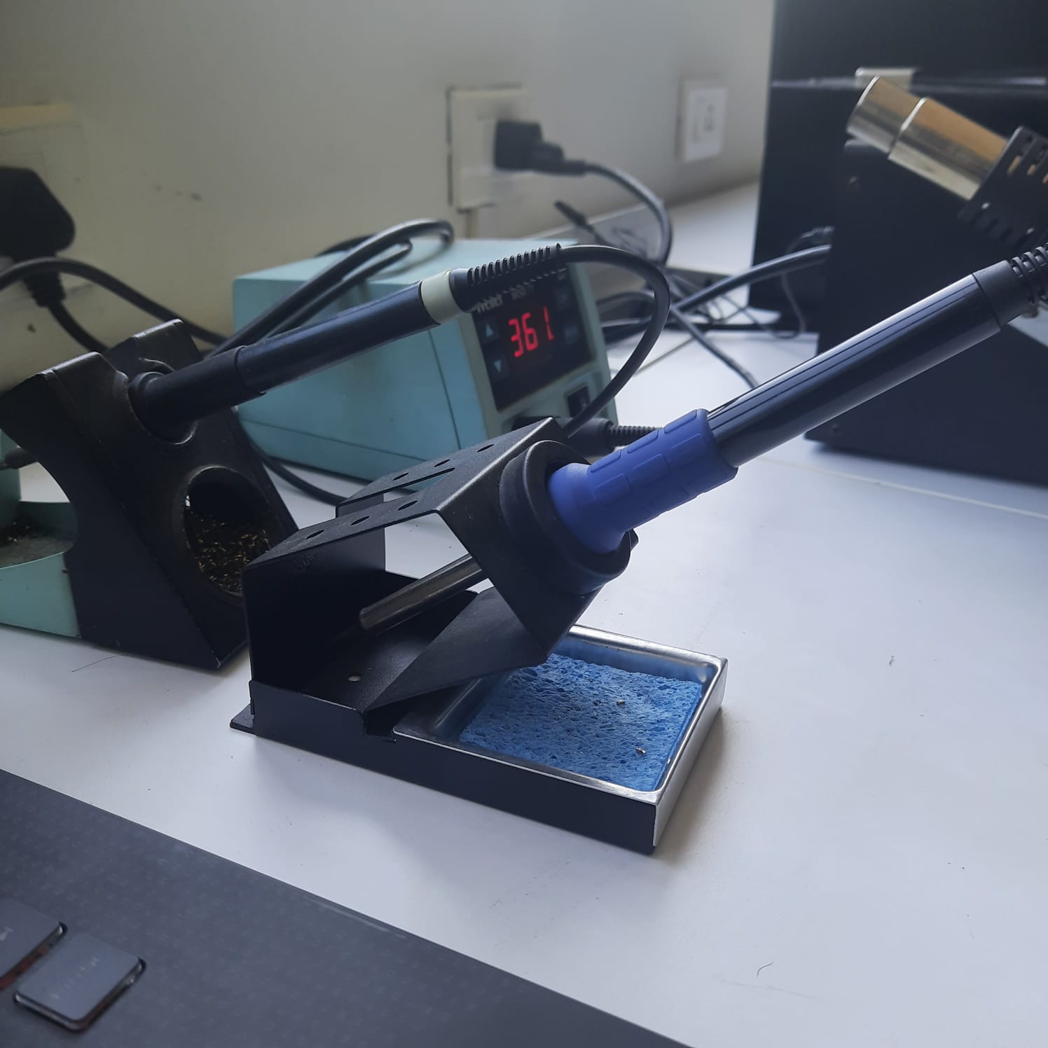
- I gathered the soldering equipments and wore a mask to avoid inhaling the fumes.
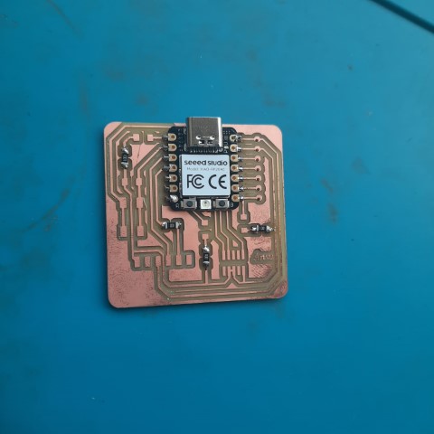
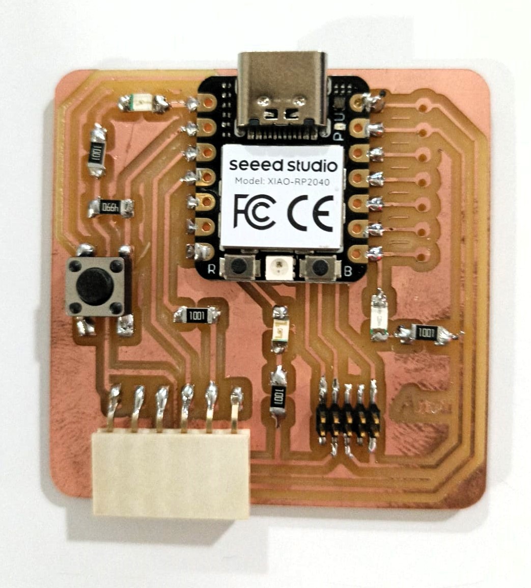
- I heated the soldering iron to about 350C and touched it to the PCB pad and placed the string of lead on it. As the solder melted and flowed, I guided it around the joint, creating a shiny, smooth solder connection. It was a satisfying moment to see the first joint successfully soldered. I started with soldering the Seed Studio XIAO RP2040. It was not as difficult as placing the resistors. The resistors were quite tiny and a lot of effort was needed to place them well.
- I continued soldering each component, taking my time to ensure each joint was neat and properly formed. The process required patience and precision, especially when working with small components like surface-mount resistors,checking and placing the LED ensuring that the polarity was correct.
- Finally, with all components soldered in place, I inspected the PCB under a magnifying glass, scrutinizing each joint for any defects. I found that at two places around the conn header, the connection was short as the solder had overflowed. Our instructor, Saheen guided me to correct it using the desouldering pump.
- Being very careful while handling the bits and ensuring it is secured tightly before milling, since if it is not secured well, it could break.
- Since I was soldering for the first time, it was something completely new. It was a bit of a task chasing the resistors around with the tweezers
- Another challenge was to ensure the polarity (looking for the green line behind the LED which corresponds to negative) was correctly placed.
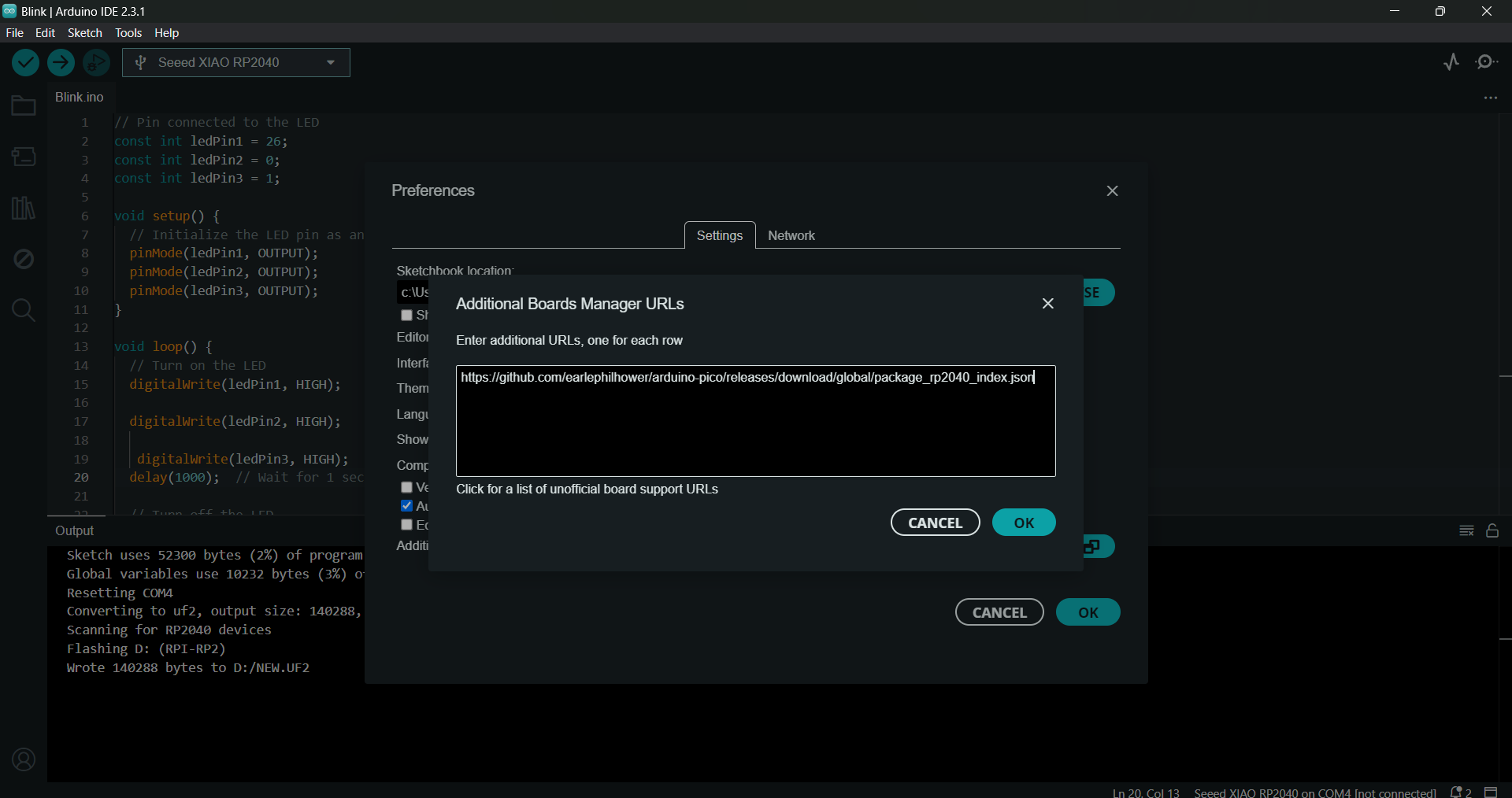
- Open the Arduino Program. In File->Preferences, we will add the URL of the additional boards that you can find here.
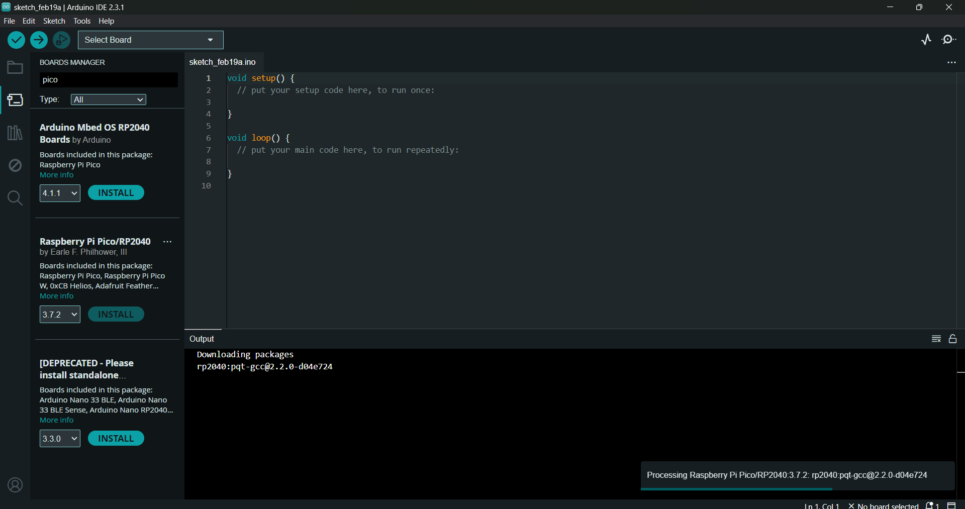
- The next step is to download Pico in the boards manager. Tools->Board->Board manager
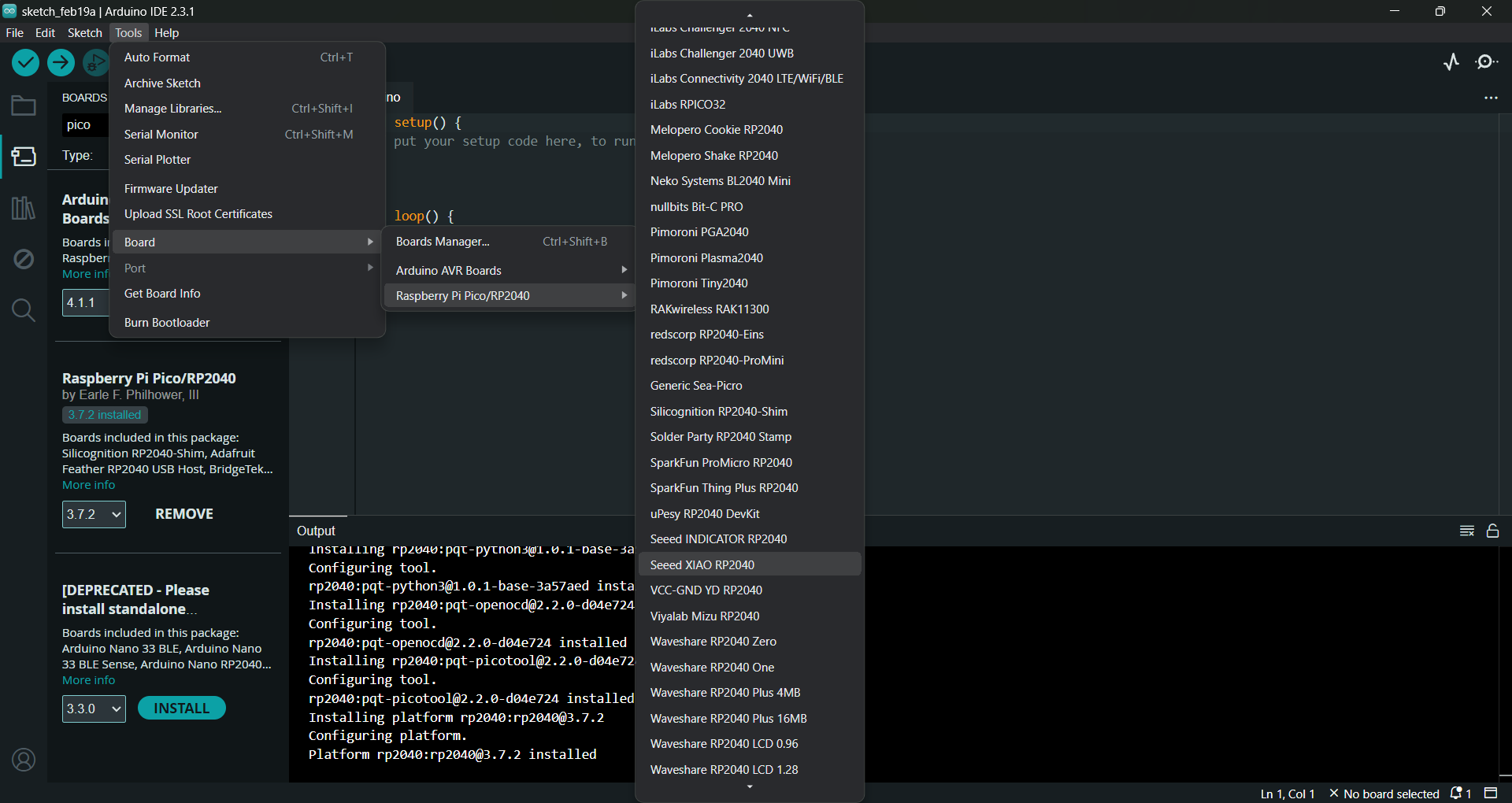
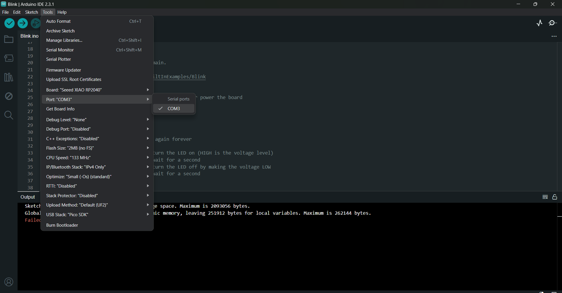
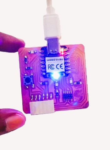
- We configure the Arduino IDE for the Seeed Studio XIAO RP2040. The Seeed Studio XIAO RP2040 will appear in the COM port
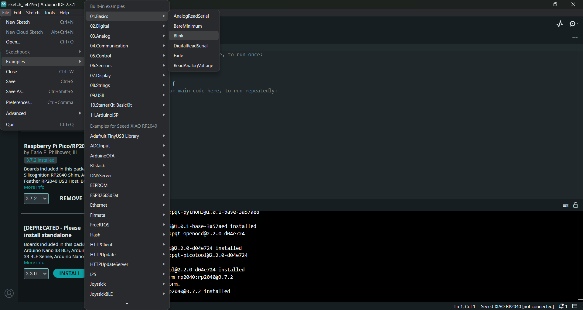
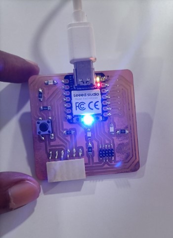
- Load the Blink Program to check the in-built LED in the Seed Studio XIAO RP2040
- This program is to light up the three LEDs simultaneously
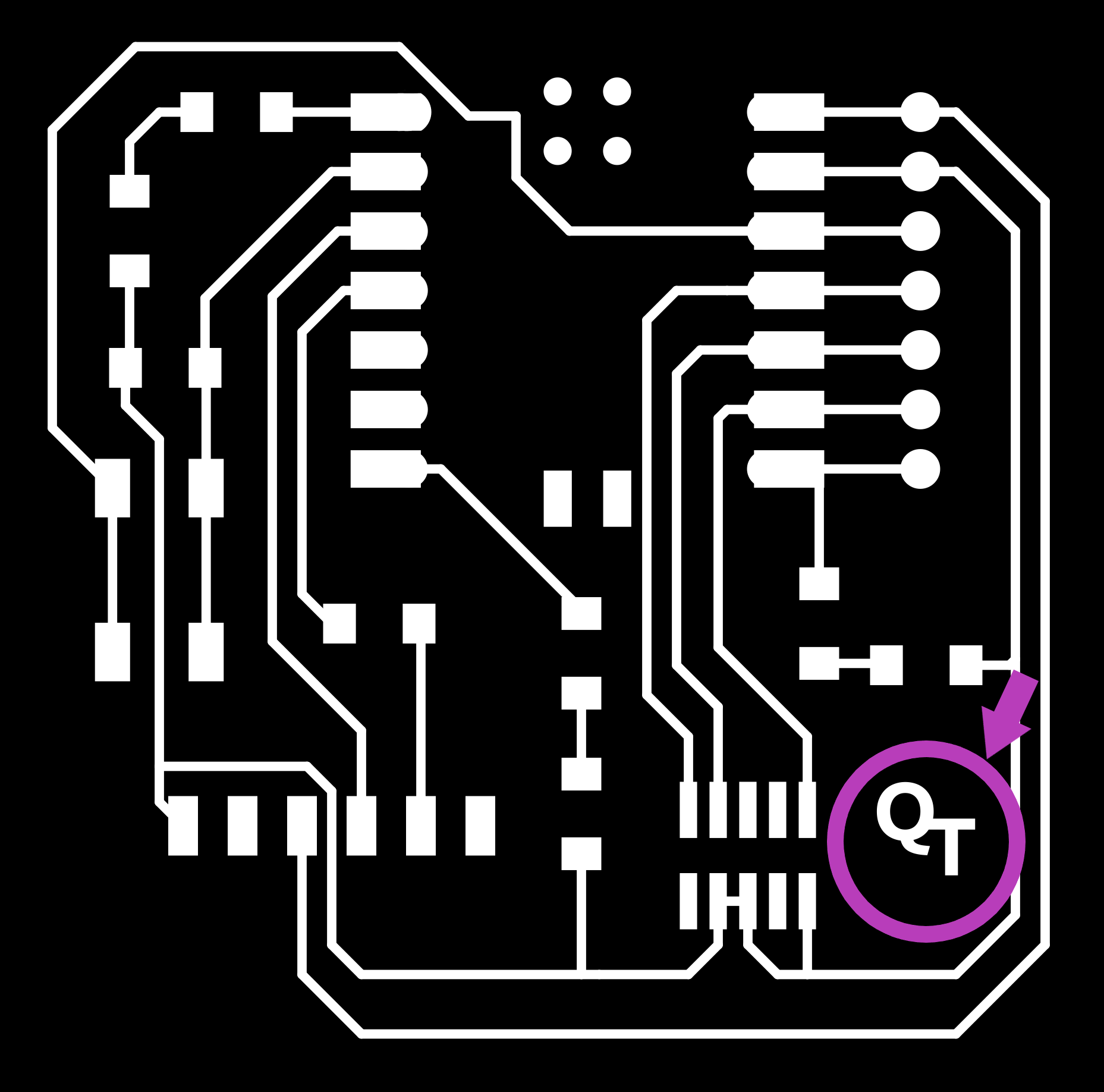

The edited file:
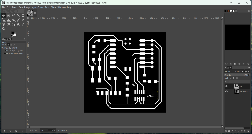
.jpg)
.jpg)
.jpg)
.jpg)
.jpg)
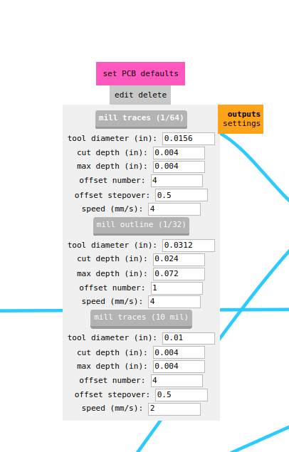
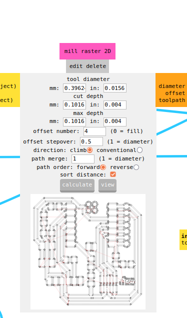
To generate the toolpath, change to mill outline(1/32) as shown:
.png)
.png)
The toolpaths for milling:
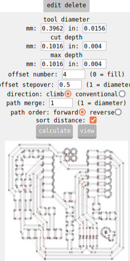
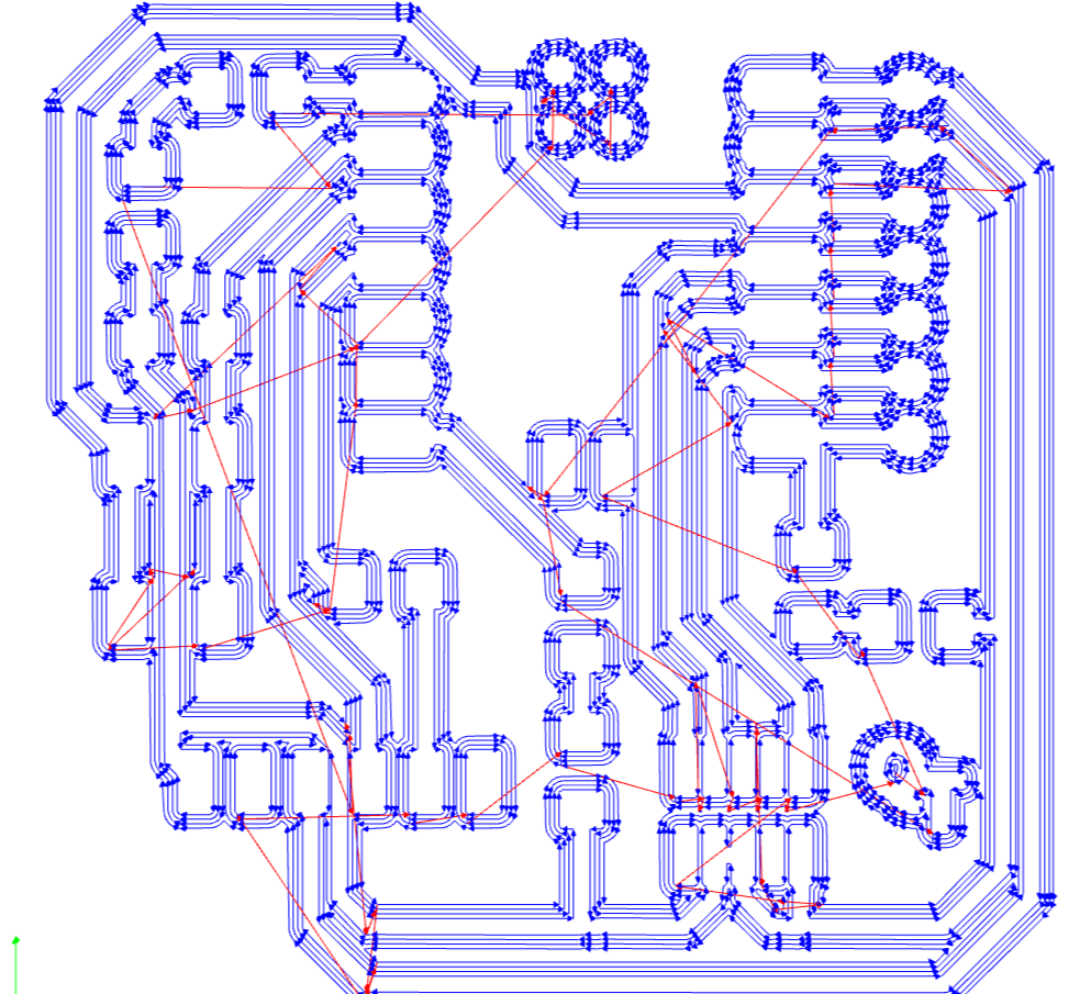 The toolpaths for drilling:
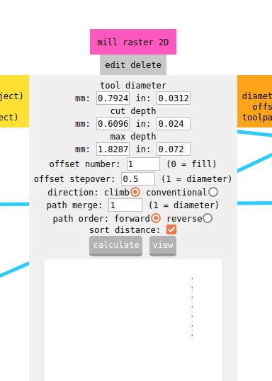
 The toolpaths for cutting:
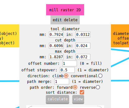

Soldering
Soldering is the process of attaching electronic components to the
board by using solder, a low-melting-point metal alloy. The solder forms a
bond between the component leads and the copper pads on the PCB, creating electrical connections.
Soldering is a completely new experience for me. It felt both exciting and intimidating. It felt like solving
a puzzle and I soon started enjoying it! I did a couple of test soldering
on an old board after removing the resistors on them and soldering them back.
These are the steps I followed for soldering my first PCB:
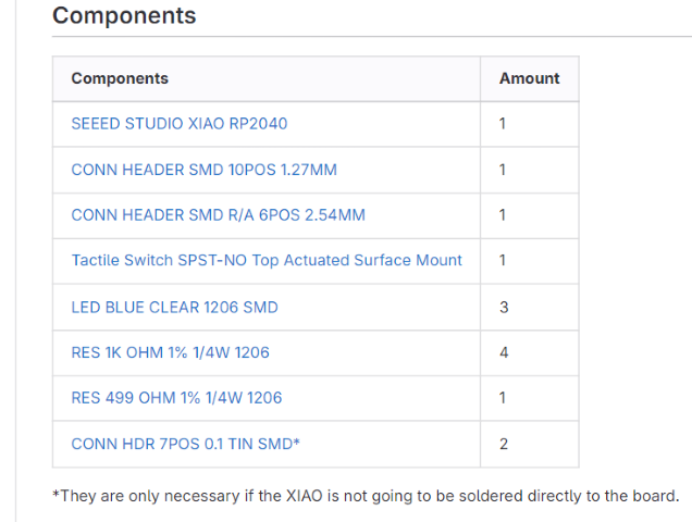
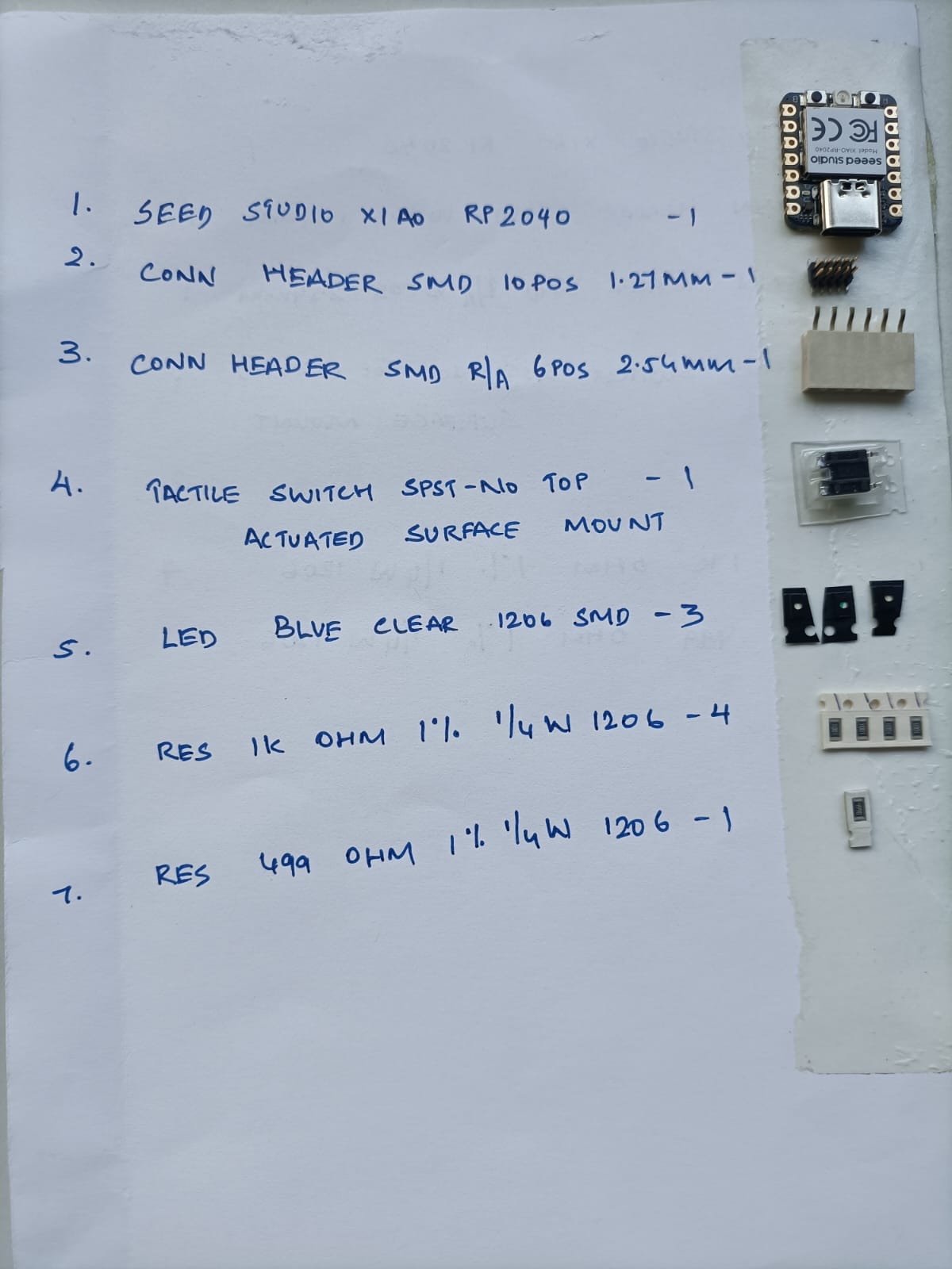
Instead of three blue LEDs, I decided to take three different colours, green, blue and red.
Problems faced
Arduino IDE
The open-source Arduino Software (IDE) makes it easy to write code and upload it to the board. This software can be used with any Arduino board. It contains a text editor for writing code, a message area, a text console, a toolbar with buttons for common functions and a series of menus. It connects to the Arduino hardware to upload programs and communicate with them. I didn't have Arduino IDE in my laptop, so I had to download it from here: Arduino Software The Fabcloud you can clearly see the steps required to use as a hello board. The steps mentioned in the fabcloud are :
Programing the LED blinking
// the setup function runs once when you press reset or power the board
void setup() {
// initialize digital pin LED_BUILTIN as an output.
pinMode(LED_BUILTIN, OUTPUT);
}
// the loop function runs over and over again forever
void loop() {
digitalWrite(LED_BUILTIN, HIGH); // turn the LED on (HIGH is the voltage level)
delay(1000); // wait for a second
digitalWrite(LED_BUILTIN, LOW); // turn the LED off by making the voltage LOW
delay(1000); // wait for a second
}
// Pin connected to the LED
const int ledPin1 = 26;
const int ledPin2 = 0;
const int ledPin3 = 1;
void setup() {
// Initialize the LED pin as an output
pinMode(ledPin1, OUTPUT);
pinMode(ledPin2, OUTPUT);
pinMode(ledPin3, OUTPUT);
}
void loop() {
// Turn on the LED
digitalWrite(ledPin1, HIGH);
delay(100);
digitalWrite(ledPin2, HIGH);
delay(100);
digitalWrite(ledPin3, HIGH);
delay(100); // Wait for 1 second
// Turn off the LED
digitalWrite(ledPin1, LOW);
delay(100);
digitalWrite(ledPin2, LOW);
delay(100);
digitalWrite(ledPin3, LOW);
delay(100); // Wait for 1 second
}
Reflow Soldering
Reflow soldering is a process in which a solder
paste is used to temporarily hold electrical components to their attachment pads
on a PCB, after which the assembly is heated over a carefully controlled thermal profile inside an oven in order to solder the joint.
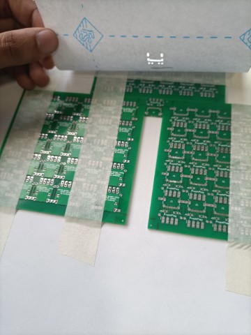
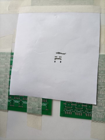
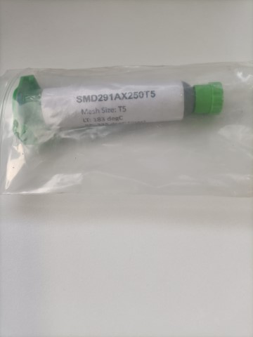
Once the components are placed on the reflow paste, it is carefully placed in the Reflow oven.
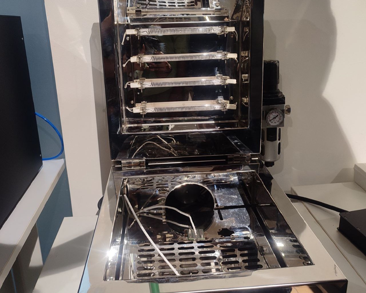
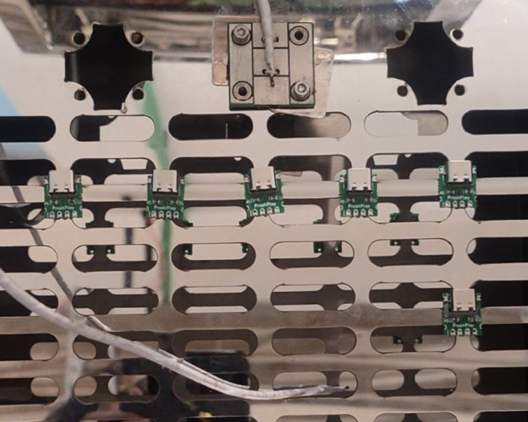
The oven can be connected to our smartphones via WiFi, allowing us to monitor its temperature remotely. Through a mobile interface accessed over WiFi, users can track temperature changes during various phases of operation.
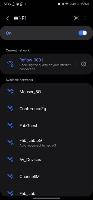
Connect to :https://reflow-user.zoidlabs.com/.The following were selected:
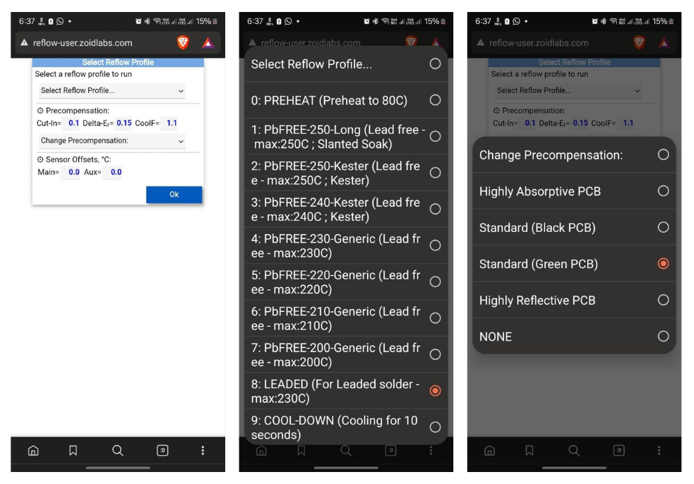
a. Preheat Phase: The purpose of the preheat phase is to remove any moisture or contaminants from the components.
Typically, the preheat phase involves ramping up the temperature slowly to avoid thermal shock to the components, usually reaching a temperature between 100°C to 150°C
b. Pre-reflow Phase: The purpose of the pre-reflow phase is to further activate the flux in the solder paste, removing any remaining contaminants and promoting proper wetting and solder joint formation when the solder reflows.
c. Soak Phase: During this stage, the temperature is gradually increased to ensure uniform heating across the assembly. This helps prevent thermal shock to components and ensures even melting of the solder.
d. Reflow Phase: In this phase, the temperature is raised above the solder's melting point, typically ranging from 183°C to 250°C (361°F to 482°F) for lead-free solder. This causes the solder paste to liquefy, flow, and create solder joints.
e. Cooling Phase: After the reflow phase, the assembly undergoes controlled cooling to solidify the solder, resulting in robust electrical and mechanical connections.
The profiles can be monitored and the status can be viewed.
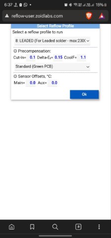
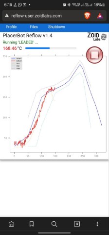
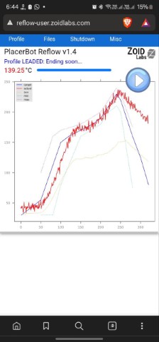
Once the PCB is ready, we can take it out and observe under the microscope to check whether it is fine. If there are any shorts, it can be altered with the soldering wick.
And this is the final result!
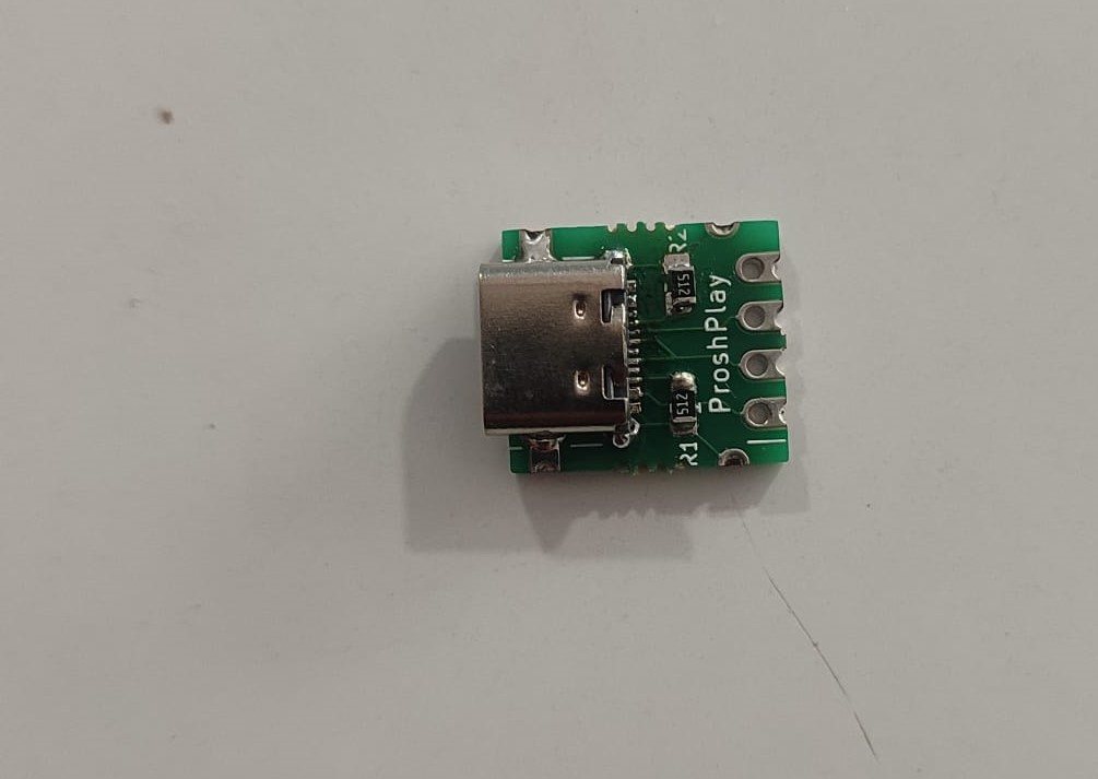
Hero shots

Design files
File 1 for MillingFile 2 for Milling
File 3 for Milling
Edited file for Milling
