Computer Controlled Cutting
Hero Shot
Assignments
- Group Assignment
- Characterize your lasercutter's focus, power, speed, rate, kerf, joint clearance and types
- Individual Assignment
- Cut something on the vinylcutter
- Design, lasercut, and document a parametric construction kit, accounting for the lasercutter kerf, which can be assembled in multiple ways
Vinyl Cutting
Vinyl cutting is a technique used in crafting intricate designs and lettering from sheets of material. The vinyl cutter uses a small blade to precisely cut through the top layer of the vinyl without cutting through the backing. The machine follows the vector paths created in your design. For vinyl cutting I used Portrait 2 vinyl cutter from Silhouette.
Vinyl cutter Portrait 2 from Silhouette
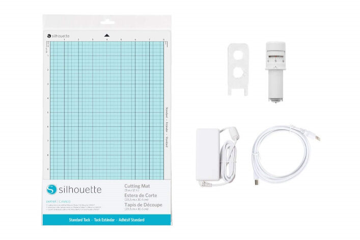
Accessories for the vinyl cutter.
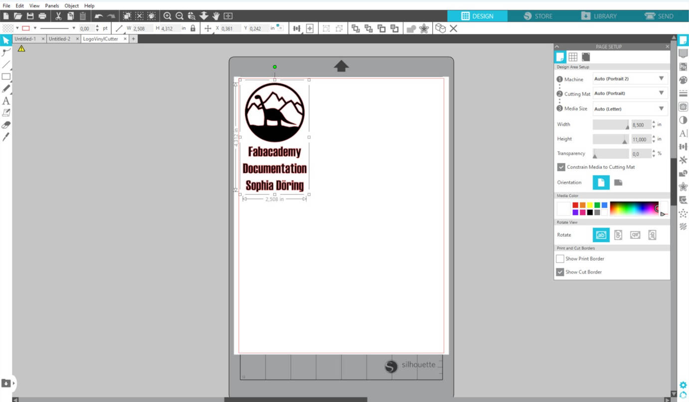
2D Design
For the 2D design I used my logo design from the first week (see here). I wanted this logo to be on my
Fabacademy documentation book. Therefore, I altered it in a
way that the program Silhouette Studio was accepting it the way a wanted it to be cut, as silhouette only excepts clear lines and single objects
in a raster file:

- Go to "File" and select "Document properties"
- Enter the measurements of the book or the size you want this design to be
- For the mountains and the circle around them:
- Remove the fill and enable the stroke
- Increase the stroke width how you prefer it
- Go to "Path" and click on "Stroke to Object"
- Remove unwanted parts of your object if necessary
- Align all object in the way you want them
- Select all objects, go to "Path" and click on "Union"
- Use the "Edit Test" tool (press T) and enter text
- Go to, object and select "Align and Distribute Objects" and align the objects in your preferred way
- Select your text, go to "Path",a nd click on "object to path" (otherwise silhouette does not recognize the text)
- Export the file as a .png file
Preparation and Cutting
To start with your cut you need to decide for a material. I used dark blue sticker foil for my design. To prepare your design:
- Cut your foil to right size for your design
- Cut a small piece from foil for testing
- Mount the foil WITH the back coverage on the sticky side your cutting mat
- Insert the cutting mat in the vinyl cutter
- Click on the "up" arrow
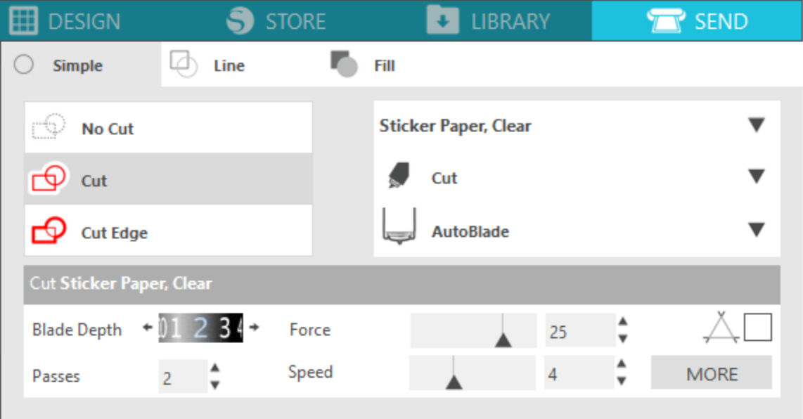
- Go to "Design" in the software Silhouette Studio and select the default settings your material (I used "sticker paper clear")
- Connect to your vinyl cutter by cable or bluetooth with your computer.
- Click on "Test" in Silhouette Studio, for testing your settings
With these settings, I inserted the foliage for my design and I started my cut. The cut went smoothly with no damage of the foil or tears.
Postprocessing the Cut
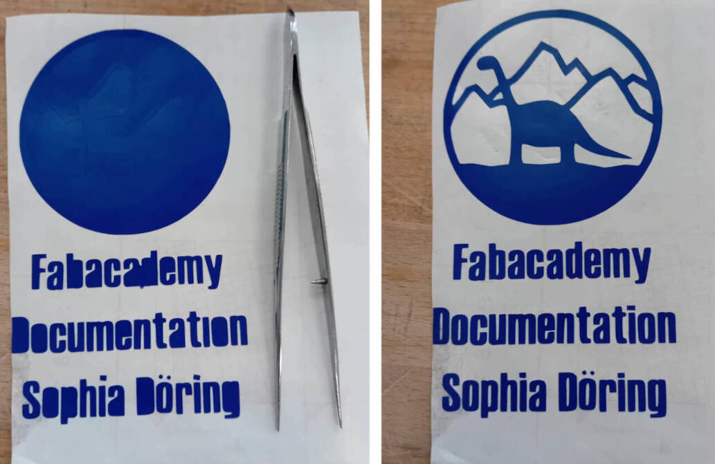
After completing the cutting process, the next step is to weed the excess vinyl from your design. I started by removing the larger outer pieces, then use a pair of tweezers to delicately remove the smaller pieces within the letters and intricate parts.
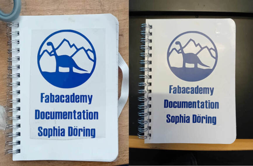
Once my design was fully weeded, it was time to transfer it to my documentation book using transfer tape. I placed the transfer tape over the entire design, ensuring it covers the entire surface. Then I pressed it down firmly to adhere to the vinyl.
I carefully peeled off the backing of the vinyl, leaving the design attached to the transfer tape. With the design now exposed on the transfer tape, I aligned it precisely with the desired page in my documentation book. Take your time to position it accurately .
Note: You can also first put your sticker on your surface and then weed it. But to be sure, that your surface is not scretched or ripped by weeding the sticker the following application is better suitable.
Laser Cutting
In this week assignment the main focus was learning the process of laser cutting: modelling a design acceptable to lase cut, operating a laser cutter, finding the right parameters for a material, and possibilities of assembling.
Instruction and Operation
Description and Preparation
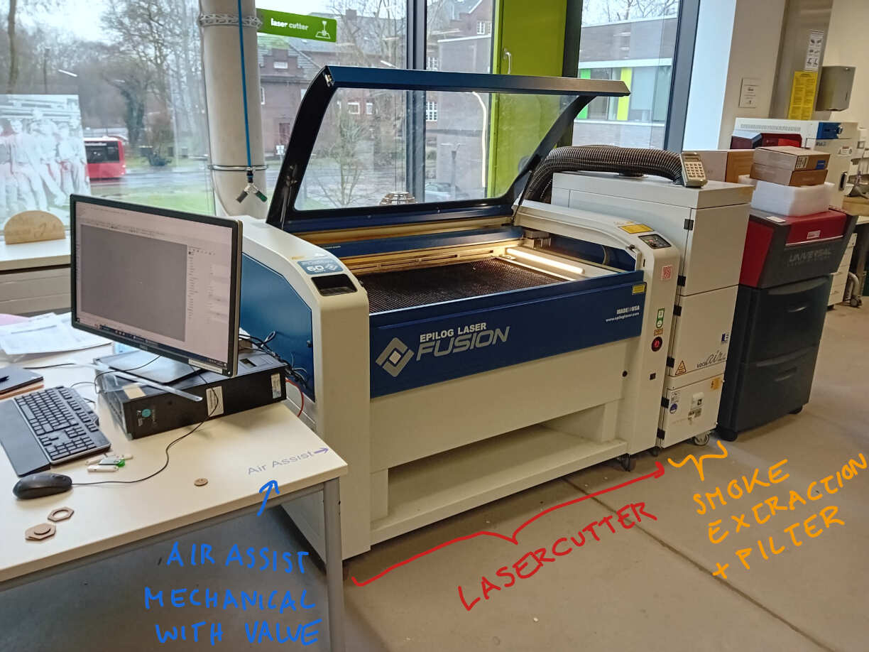
The laser cutter I used in Kamp-Lintfort has 60 W CO
The heart of a laser cutter is, of course, the laser itself. The important medium in the CO
To manage the heat generated by the laser, a water cooling system is employed, automatically activated in the FabLab in Kamp-Lintfort.
To address dust and smoke produced during cutting directly beneath the beam, an air assist system is connected to the laser head. This not only aids in eliminating debris but also reduces the likelihood of material burning and prevents the lens from becoming cloudy.
Furthermore, to extract smoke within the entire bed of the laser cutter, a smoke extractor is employed. This device sucks in and filters the air before expelling it from the building, maintaining a clean and efficient working environment.
IMPORTANT: Turn on the air assist and the smoke extractor BEFORE operating the laser cutter!
Operation
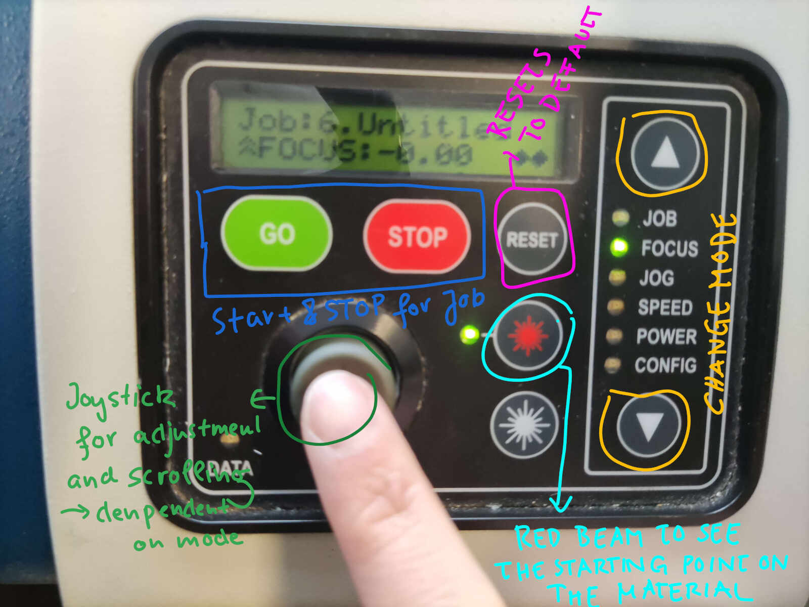
The origin of the laser cutter is by default on the upper left corner. Therefore, it is a good idea to put the material on the upper left corner of the bed. To adjust the starting point of your cut:
- Change mode to "jog"
- Move the jog with the joystick
- Press down the joystick to set the start
- Change mode to "focus"
- Move the bed up or down with the joystick
- Press down the joystick to set the z-axis value
For starting your job you can use the "GO" button and for stopping press "STOP". It is more a pausing you can continue the cut, when pressing "GO" again.
IMPORTANT: Do not leave the laser cutter alone, while cutting! (Separation anxiety is real!)
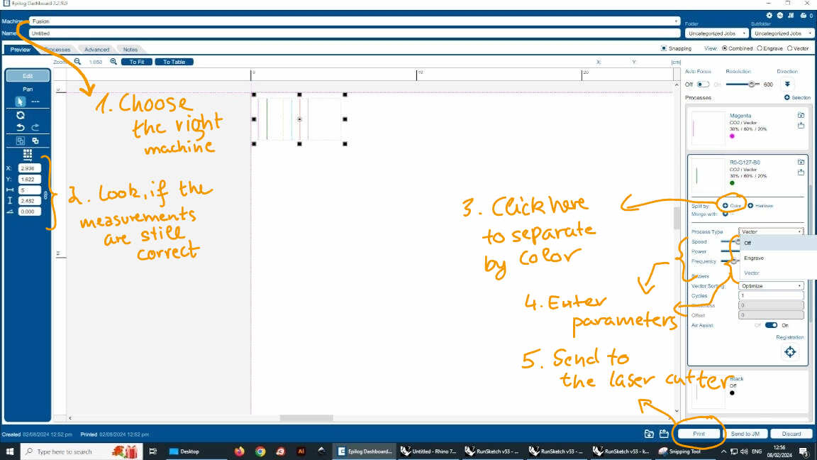
Sending Files to the Laser Cutter
The desktop pc in the lab next to the laser cutter was used for sending files to the laser cutter as it is directly connected to the computer. The file you created can be a vector file, or sketch directly created in Rhinoceros. I mainly used vector files:
- Open your file in Inkscape on the desktop
- Organize operations by assigning consistent colors to group different elements
- Press Ctrl + P as a printing command
- Select "Epilog Laser Fusion" as the printer and select "Vector" as type of graphic
- Select the "Epilog Fusion" as your laser cutter (there is another smaller laser cutter in the lab also)
- Click on the "Color" Button on the right side of the window, where you can see your job
- Enter the right parameters for every color
- Click "Print"
2D Design
For this assignment I created several designs. The two designs and laser cut jobs for my individual assignment are described in the following chapters. The 2D modelling for the comb used for the joint clearance in the group assignment can be found in the last week's assignments (see here).
Modular Kids Toy Parts
The first design and model of these toy parts is described in the last week's assignments (see here). As I have mentioned there, the design in Inkscape is unnecessary complicated to adapted to a different kerf and thickness of the material. Additionally, I wanted the dog-bone raddi and chamfers to be included in the design. Therefore, I designed this part in Fusion a second time.
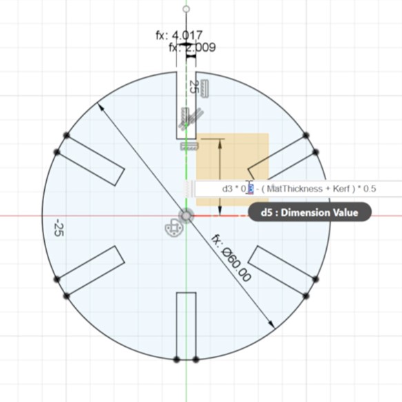
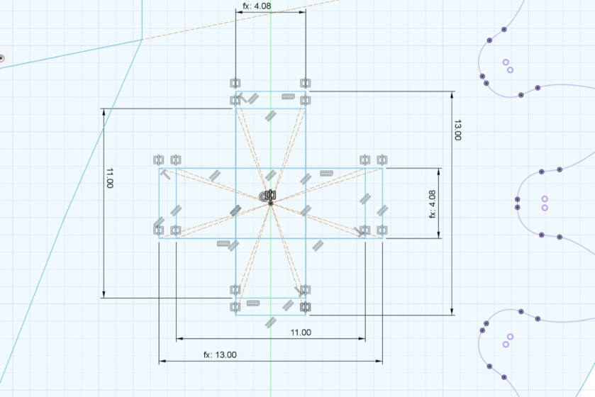
I created a circle and a rectangle (parametric sizing). Then I created a circular pattern of the rectangle.
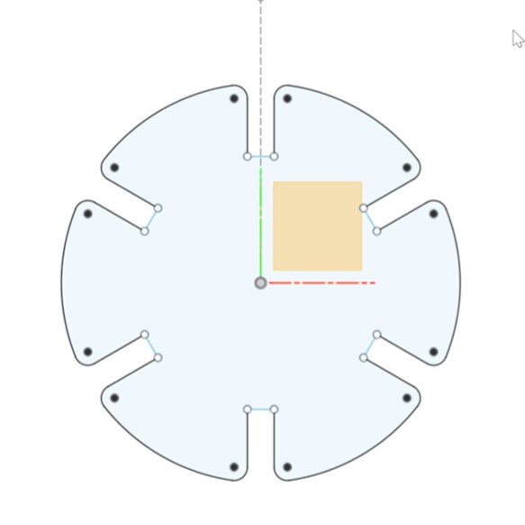
I added fillets rather and chamfers and the dog-bone radii and cloned them with a circular pattern, too.
The design of the toy parts is parametric and the parts can be assembled in multiple ways. As parametric values, I used the thickness of the material in the lab, which was 4 mm plywood and the resulting values for the joint clearance from the group assignment (see here), which resulted into thickness + 0.25 kerf for a slightly loose fit t be able to disassemble the part easily.
Gripper
In my exploration of assignments from previous years by fellow students, I sought inspiration for my own project in this assignment. It became apparent that while most assignments met the requirements effectively, they predominantly lacked movement or functional elements. Consequently, I made the deliberate decision to craft something not only satisfying the assignment criteria but also possessing functionality and movement – an interactive gripper.
To design the gripper, I employed a combination of Fusion 360 and Inkscape. The initial step involved inputting the essential parameters, such as thickness and kerf, into Fusion 360. For detailed insights into the creation of a parametric design using Fusion, refer to the assignments from the previous week.
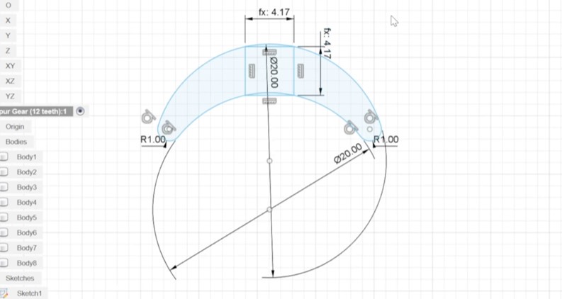
The design process commenced with the creation of a rack and pinion mechanism
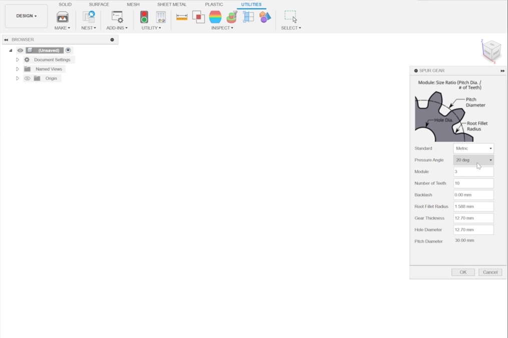
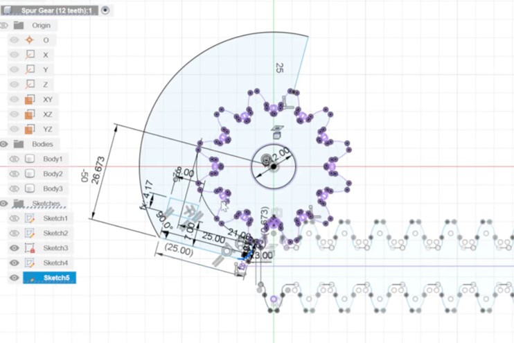
To design the gear, I utilized the Spur-Gear Add-in within Fusion 360. To access Add-Ins, navigate to "Utilities" and click on "Add-Ins" in the menu. The specific gear I created had a module of 3 and featured 10 teeth, resulting in a pitch diameter of 30 mm (calculated as module multiplied by the number of teeth).
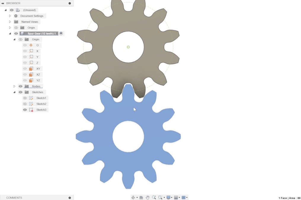
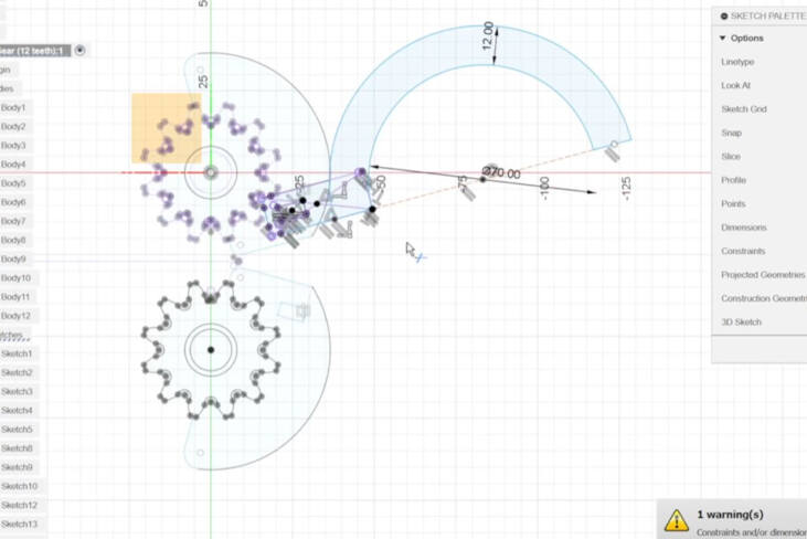
For the creation of the rack, I duplicated and shifted the gear by the pitch diameter distance. Additionally, I rotated the original gear by 18° to verify the compatibility of the teeth. This rotation angle (18°) was determined by dividing the full circle (360°) by the number of teeth (10) and then dividing by 2 (360°:10:2).
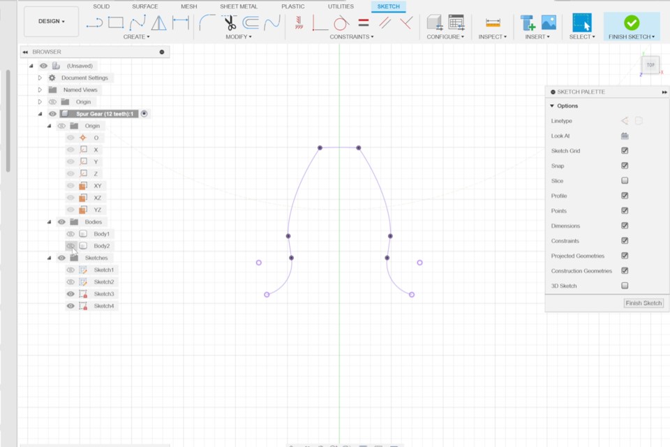
Following that, I initiated a sketch in the same plane as the gears and utilized the "project" feature (by pressing P) to bring one tooth into the sketch.
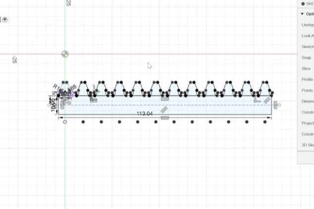
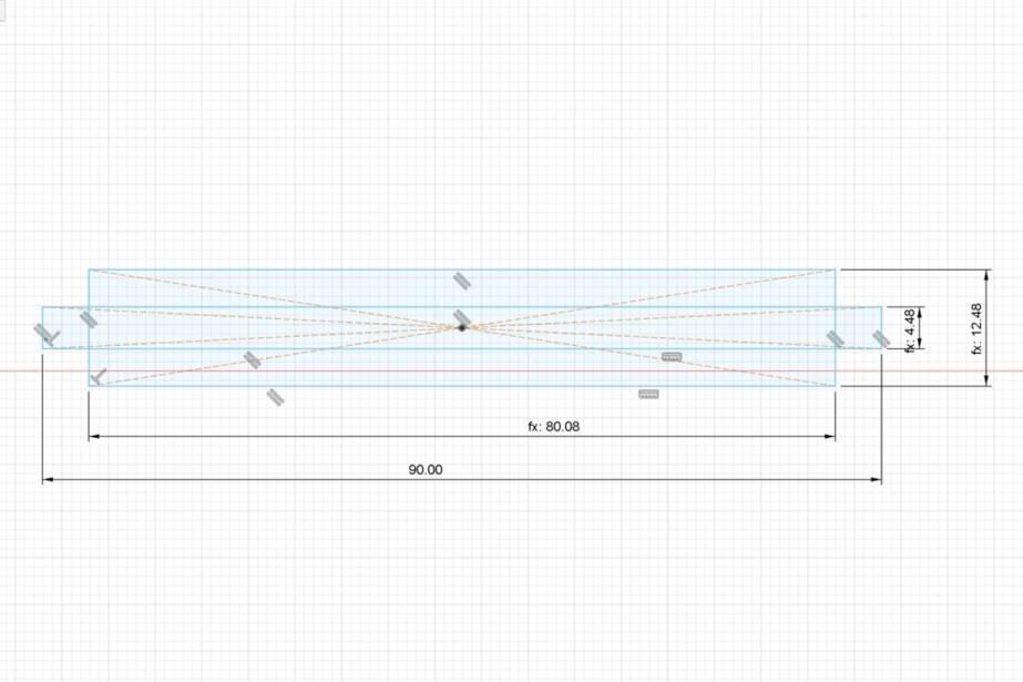
Then I created a rectangle starting with the first tooth. and the length of diameter*pi.
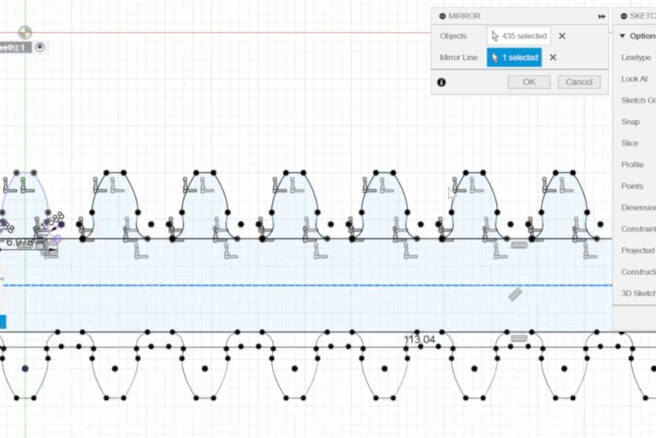
I then mirrored the teeth.
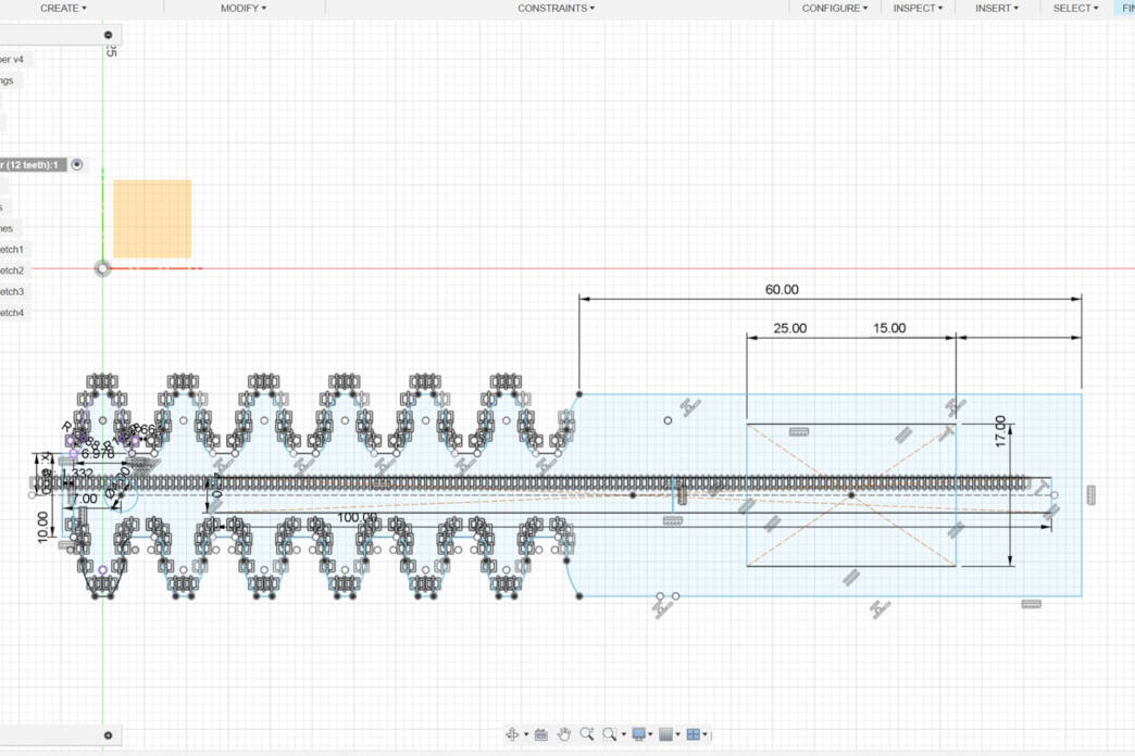
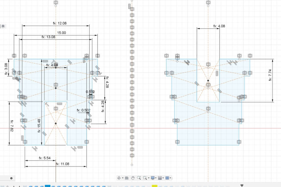
Subsequently, I recognized that only half the length of the rack was required. To address this, I designed a handle at the right end of the rack. The presence of a rectangle in the center of the handle is intentional, as it provides free space for accommodating the rubber band, which will be utilized to close the gripper.
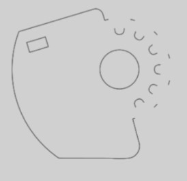
The adapter piece plays a key role in limiting the gear movement to 180° and incorporates a rectangular hole designed for interchangeable gripper types.
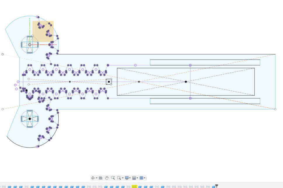
The upper piece of the gripper facilitates the movement of the gear while preventing slipping from the rack. The central rectangle serves as a grip for handling the gripper, and the side rectangle, along with the cross in the center of the front parts, functions to secure the gears in place. Furthermore, these features, in combination with the subsequent pieces in the design, help maintain the correct distance from the rack and the gears.
The crosses of the upper piece are longer than the bottom piece to keep the right distance.
For the cross, these two pieces were created. They can be put together to built the cross. the tower like shape is useful for the distances between the gear/rack and the upper and bottom pieces (distance is 0.2 mm).
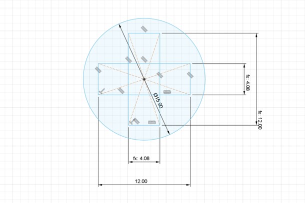
This piece is keeping the gear in place while enable the rotational movement (distance between the gear and the circle of the pies = 0.2).
This piece is needed for the upper und bottom piece to hold together and keep the distance of 0.2 mm from the rack.
The last piece was for the rubber band to stay in place.
For the grippers, I opted for two distinct designs—a round and an angular one. To ensure that the size of the connecting arm of the grippers does not interfere with the movement of the gear and the upper and bottom pieces, I projected the essential parts from the other sketches onto the gripper sketches.
The round gripper.
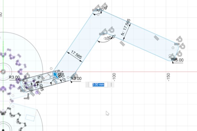
The angular gripper.
Preparation and Cutting
For the Epilog software, a vector file is needed. Therefore, all the sketches for the kids toys and the gripper were exported as a dxf (right click on the sketch, click on "save as dxf"). As projection lines are also exported this way, further worked on the sketches in inkscape to remove unwanted lines and fix the sketch for the laser cutter.
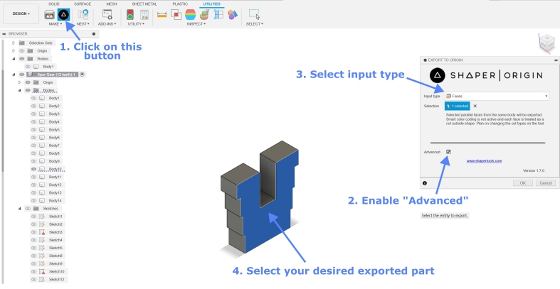
The import of the .dxf file of the kids toy work out quite well, but for the gripper file some problems occurred. Lines were missing from the design. Therefore, I searched for other solutions. As GIMP does not support vector files in general, I started to look for a way to export .svg files from Fusion 360. With the add-in "Shaper Utilities" (see here) i was able to export .svg files. This add-in very powerful. Faces, projection of bodies, as well as sketches can be exported as svg. I used the add-in to export the sketches as .svg files and imported them into Inkscape to one file to make the design exportable for the Epilog software.

Assembling
Modular Kids Toy Parts
The joints for the various components of the kids' toy were exceptionally well-fitting, thanks to the joint clearance values derived from the results of our group assignment (see here). However, it was noticeable that the assembly and disassembly of the toy required varying degrees of strength. This discrepancy is likely attributed to the nonuniform nature of the material.
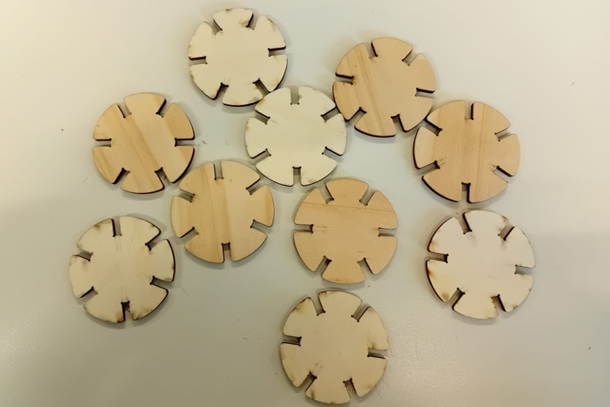
The parts.
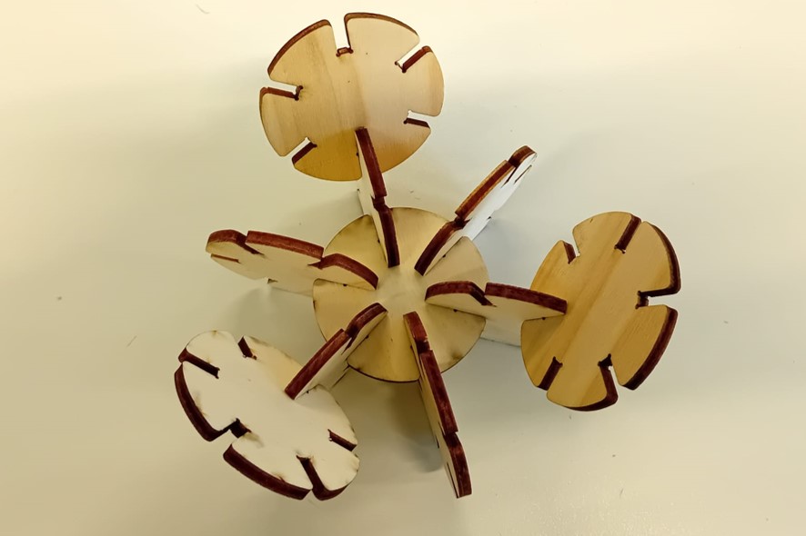
The assembly.
Gripper
During the assembly of the gripper, a rubber band was incorporated to serve as an energy storage, allowing the gripper to snap back when holding an object. The individual parts seamlessly came together. However, I observed that the joints used to hold the gripper components together, such as the cross joint, were slightly looser. Surprisingly, even though I employed the same parameters for connecting the gripper to the gripper mechanism, which had a perfect fit, the joints in the gripper assembly exhibited a slight discrepancy. This variance might once again be attributed to the nonuniform nature of the material.
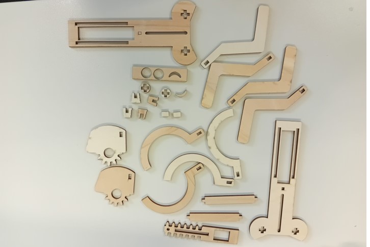
The parts.
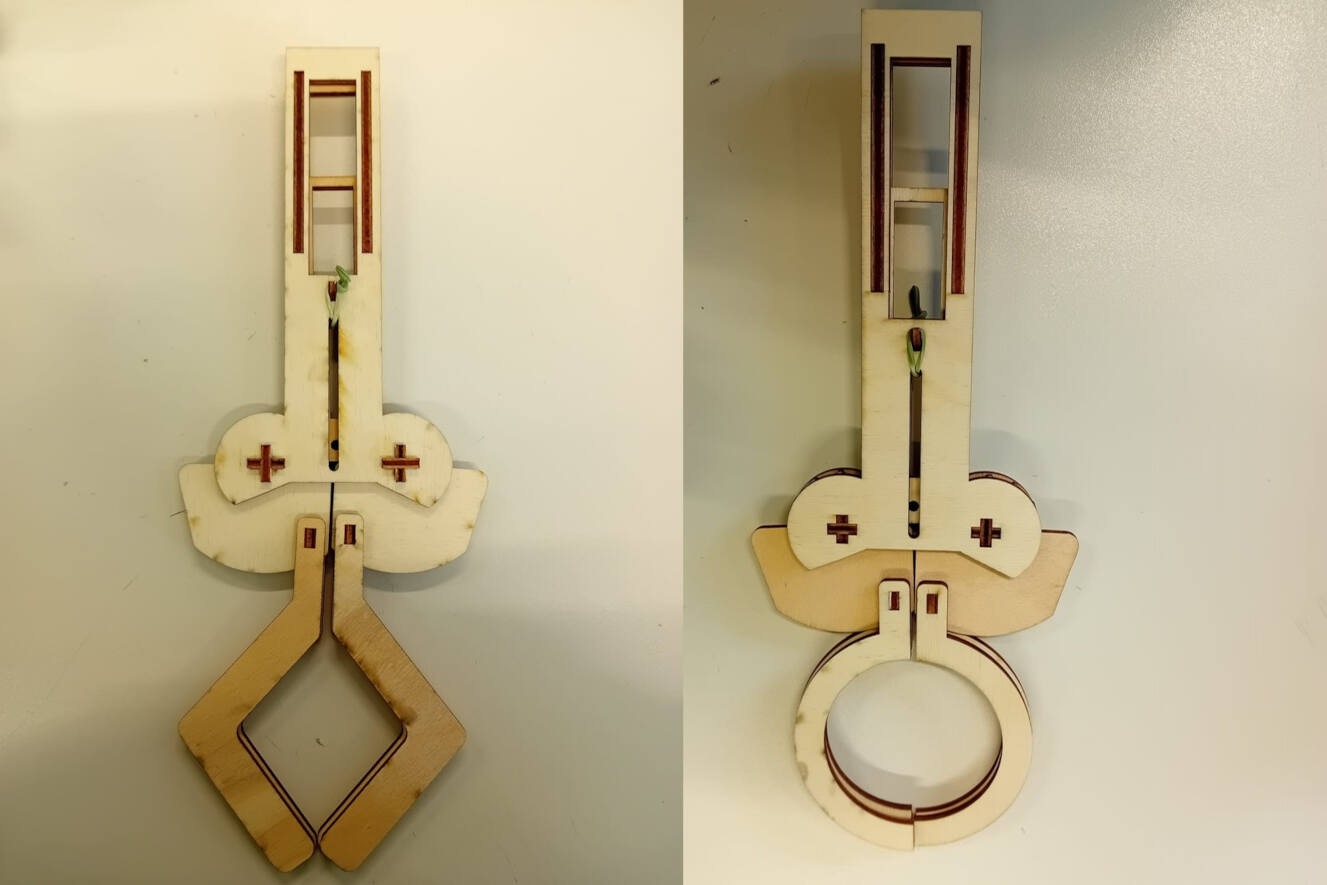
The assembly.
Evaluation
Vinyl Cutting
As I used the vinyl cutter several times now, I felt pretty save with using it for my logo. Because of this I have a lot of experience especially with creating an Inkscape file, that can be used for the vinyl cutter's software. Here are the most important things that I have learned when it comes to these two softwares:
- Always export as .png. The silhouette software excepts .dxf files, but it changed shapes and has a very bad resolution in general especially with text.
- Make sure that all the things you export are objects, convert other types like text into objects
- If you have two object on top of each other, silhouette does not recognize the lines of the object inside the other one and only the outlines. To make all objects recognizable use the logical operations in Inkscape (Difference, Union, etc.)
Laser Cutting
During laser cutting, we also noticed some strange things in the files when sending a file from Inkscape to the epilog software:
- Always keep the size of your page Inkscape (see Document properties) in a portrait format not landscape, otherwise the epilog software cut off parts.
- All objects outside the page in Inkscape will be cut of and not recognized by the epilog software
- You have to enable all strokes in Inkscape, otherwise the object is not recognized by the epilog software
On a related note, the design of the gripper appeared disorganized and lacked sufficient constraints. This resulted in various challenges when adjusting the thickness and kerf in the parametric design. Consequently, manual adjustments were necessary, and corrections had to be made to counter the alterations applied by Fusion after modifying the parameters.
Group Assignment
For the group assignment, I took the initiative to create the Inkscape file, facilitating the testing of optimal frequency, speed, and power settings for the materials. Additionally, I designed a tester comb to assess joint clearance. Collaborating with my group members, we collectively determined the appropriate distance for focusing on the material surface. Subsequently, we defined the kerf and established parameters tailored to the materials at hand, including cardboard, MDF, and plywood. Surprisingly, the process of finding the right focus and determining the kerf turned out to be more straightforward than initially expected. In our quest for knowledge, we also referred to the webpages of previous students, including Roland Grichnik, Aaron Hinkle, and Leen Nijim.
For the kerf we decided to adjust the focus in three iteration. We knew that the focus tool was more or less keeping the correct to focus the beam to the surface of the material. To be sure we started with 5 mm difference in each direction of the current focus distance to see, if there is still room for improvement. After finding a range, where the focus seemed to be better (depending on the kerf of the cut line).
Following our exploration of finding the right parameters, specifically the kerf, for the materials chosen for this assignment and future projects (cardboard, plywood, and acrylic), we encountered varying degrees of success. For cardboard and plywood, we successfully determined the appropriate parameters. However, challenges arose when working with acrylic. Despite initiating the process with the recommended settings from the machine's manual, the acrylic did not cut through as expected. Instead, the edges exhibited uneven melting, resulting in a fused appearance and slight discoloration from transparent to a less-than-ideal brown shade. Despite our efforts, which included adjusting parameters and attempting multiple cutting cycles to mitigate the melting effect, we were unable to achieve a satisfactory cut for the acrylic. Several factors may contribute to this issue. Firstly, the machine's strong air assist set at 2 bars (where 1 bar is typically recommended) posed challenges, especially with cardboard. The robust air flow caused small pieces to shift position on the bed after cutting. Additionally, differences in outcomes may be attributed to variations in acrylic types, such as casted or extruded variations. This variance can significantly impact the cutting results, adding complexity to the process. Finally, we decided to define the parameters for a different material: MDF.
Time management
My attempt to create a functional and movable project within a week proved to be challenging, resulting in a setback as I couldn't complete the documentation on time for Wednesday. The documentation itself was overly lengthy and lacked structure, largely due to the complexity of the design challenge presented. In retrospect, opting for a smaller, more straightforward project would have been more time-efficient and easier to document.
The parametric design of the gripper, while a time-saving measure, introduced complications. The sketches in Fusion 360 lacked constraints and precise measurements, causing warnings and undesired changes every time adjustments were attempted. This hindered the intended design and led to a less-than-optimal final product.
In future evaluations, it is crucial to stress the importance of project scope and simplicity, particularly when facing time constraints. Additionally, the significance of clear and concise documentation should be highlighted, underscoring its role in effective communication and project replication. Learning from this experience, a more careful approach to parametric design, including thorough parameterization and constraint application, is recommended to prevent unforeseen issues.