Hero Shot: Working Mechanism
Hero Shot: Automated Mechanism
The animation was done by Bianca Guimarães, while the video was edited by Ece Öner
Hero Shot: AI-Song
Initial Ideas
This week´s assignment is fully dedicated to the group project, which consists of designing a machine and then building it, the first step of this process was to decide what type of machine we wanted to build, so we started brainstorming ideas and discussing the possibilities.
- some type of plotter
- a robotic 3rd arm
- a knitting machine
- an automatic egg painting machine
- wire bender machine
brain storm ideas:
we democraticaly made a vote, and the automatic egg painting machine was the winner, mostly because easter was just around the corner, and also becasue it sounded fun and diferent, challenging but still within our capabilities in terms of time and resources.


we were inspired by the eggbot and the Sphere-O-Bot, these are both open source egg painting machine projects with a lot of documentation and resources available online. the next step was to devide the tasks and start working on the machine, my task was to design and build the egg holdeing mechanism.
Requirements
Planning and Allocation of Tasks
To build the egg painting machine, several tasks have to be accomplished. These are roughly divided into two categories, namely the electronics, i.e. designing and manufacturing the PCB, and the mechanical parts including a linear motion system, a pen holder, an egg holder and a frame that holds all the parts together. The actual programming and testing the complete machine was planned to be done by all of us together.
In addition to the four of us doing FabAcademy in Kamp-Lintfort, we had one person from the FabLab Bottrop joining us. Therefore, we were five people such that a single task could be allocated to a single person. Here, Jona from Bottrop choose the electronics design task as this is his profession and this had the least interfaces with other tasks. The remaining task were split among the KaLi people. In total, the tasks were allocated as follows:
| Task | Responsible Person |
|---|---|
| Linear Motion System | Sophia |
| Pen Holder | Frauke |
| Egg Holder | Bianca |
| Frame | Ece |
| Electronics | Jona |
Planning-wise we did not create any chart to visually show when task had to be done. However, there were several aspects we agreed on regarding time management for planning.
- The mechanical design is ready after one week (from 28th of March to 4th of April)
- The mechanical parts are manufactured within the first four days of the second week (4th to 7th or April))/li>
- The mechanical parts are assembled on the second Monday (8th of April)
- The electronics are manufactured on the second Monday (8th of April)
- The programming and testing is done on the last two days (8th and 9th of April)
Design and Fabrication
Linear Motion System
In this chapter the design and fabrication of the linear motion system is shortly described. For any further information have a look into the individual page of Sophia Döring.
The linear motion system enables the movement of the pen holder along the y.axis of the machine. There are several principles and designs existing to create linear motion. For the design we defined these specified requirements:
- The linear motion of the rail must be a translation of the rotational movement generated by a NEMA 17 stepper motor
- The linear motion rail must offer high precision to ensure accurate movement of the pen along one degree of freedom
- Smooth motion is essential to prevent any jerky movements or inconsistencies in the plotted lines.
- The linear motion rail should provide secure attachment points or mounting options to the frame
- While meeting all the necessary requirements, the linear motion rail should also be cost-effective

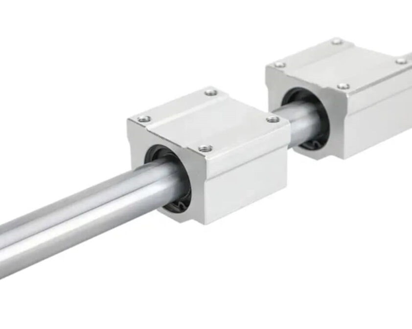
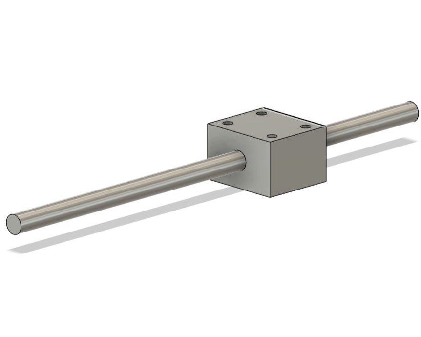
The rail system was not fabricated in the lab as only off-shelf components were used for the system.
Utilizing resources available in the lab, I opted to incorporate a linear bearing and shaft to constrain the degrees of freedom. I proceeded by reverse-engineering the critical dimensions of both the linear bearing and the shaft, were they would be connected to the penholder and the frame.
Pen Holder
The pen holder of the egg painting machine should - as the name says - hold the pen such that the tip is in contact with the egg shell. In the first meeting about the general layout of the egg painting machine, we already described some basics about the pen holder and the interfaces with the other teams. These are for example, that it will be moved by the translation stage and therefore needs to be attached to it and its parts. It should furthermore position the tip of the pen on the eggs shell.
There are many things that need to be considered before designing the pen holder. Some major aspects are the method of how to retract the pen, the contact pressure and the vertical travel it should be able to accomplish. In general, the requirements for the pne holder were specified to the following.
- Attach to translation stage
- Retractable with a servo motor
- Tip of pen touches the egg shell on the top
- Contact pressure between min. 0.5 N and max. 2 N
- Allows for a vertical travel of 20 mm
- Pen diameters are max. 18 mm
For the details on the design decisions, please refer to Frauke's documentation.
The design itself is relatively simple. There is a part that stands vertically and mounts to the translation stage consisting of a linear slide and a threaded rod with a nut. In the top of the part, a hinge is present which connects to another part, which is referred to as the lever arm. On its end, the pen is mounted. With the hinge, the pen itself can be moved up and down in a slightly curved movement. On the lever arm, a slot is present to be able to attach some weight to it to precisely adjust the contact pressure. Without the weight, the tip of the pen is loaded with about 0.5 N, depending on the weight of the pen. This is how the design looks like:


As these parts are highly customized, these parts were 3D printed with PLA on a Bambu Lab X1 Carbon with support structures from PLA. To ease the removal of the support, three layers of the interface between the support and the actual print were printed from PETG. In the images below, you can see the PLA in black and PETG in green in the slicer software Bambu Studio.


After the print was completed, the support structures were removed. After this, the assembly could start. Firstly, the two bearings were pressed into the positions at the hinge. The tolerances here were big enough to easily press it in without breaking the part. Next, the hinge was completed by inserting a 5 mm rod through it. Then, the servo was positioned between the arms and attached with two M3x12 screws.
Lastly, the pen holder was mounted onto the translation stage. The first step was to tighten the screws in the bottom that mount it to the linear slider. Then, the nut that is mounted to the threaded rod that generates the motion is attached to the pen holder. In the end, the threaded rod is inserted through the hole of the pen holder and screwed into the nut. This finished the assembly. In general, for more information please refer to Frauke's documentation


Egg Holder
The egg holder is composed of two parts: one that is controlled by the motor and spins the egg, and the other that helps hold the egg up and follows the spinning motion The requirements for the egg holder were defined as:
- Hold the egg without any adhesive
- Connect to the motor
- Spin the egg
- Adjust for the different egg sizes


The design of the egg holder was done in Fusion 360, and the components were either sourced at the lab (nuts, screws, spring, rods, bearings) or 3D printed (egg holding parts). The design and assembly of this was done by Bianca Guimarães, and more in-depth information can be found on her individual page.
The design of this part went through a few different versions until a final version was decided upon. The tricky part was to make sure the egg would stay in place while spinning, but in general, the design is actually quite simple. The part that's connected to the motor is just that, a solid 3D printed part with a small crater where the tip of the egg sits on, and on the other end, the place where the motor shaft is inserted and secured with a screw and nut.

The 3D printed parts were printed on the Prusa MK3 with TPU, while the inner diameter of the components used was M3.


Frame
The frame is the component to align and position all other components. Therefore, these requirements were defined:
- The frame must incorporate designated mounting points to seamlessly accommodate the linear motion system, egg holder, and electronics. This ensures precise alignment and ease of assembly.
- It is imperative that the frame offers robust stability to securely hold all components in place during operation
- The frame design should incorporate a user-friendly system allowing for easy adjustment of the egg holder's length
- The frame should be lightweight and compact enough to be comfortably carried by two hands, facilitating relocation and deployment in different settings
- The frame design should prioritize simplicity and ease of fabrication to minimize production time
- Opting for materials and manufacturing techniques that strike a balance between affordability and performance ensures that the frame remains budget-friendly without compromising on quality or functionality.
Frame 1.0
Before going through the 3d drawing of the frame on Fusion360, I did a sketch and talked with my how I can connect the egg holder and pen holder parts to the frame. I listed the components that must be attached to the frame such as serval motors, ball bearings, carriage slider, and shaft. Frame is one of the most important parts of the project because it connects all the pieces.
For this reason, I contacted all my friends who were responsible for the design of the other parts and tried to understand how I could adapt the parts they designed to the frame. At this stage, details such as the length of the pen holder and the points where the egg holder connects to the frame were the factors that affected the design. In addition, there had to be a space in the frame where the slider could be positioned. With all this in mind, I started my work with a sketch and determined the dimensions of the frame.

After the first drawing of the design, I tried to find solutions on how to connect the other parts to the frame in detail. Here I also got the opinions and help of my group mates. After completing these details, I started my drawing in Fusion360.
- Serval motor- Drill screw holes on the design.
- Carriage Slider - Drill screw holes on the design.
- Ball Bearing- Press fitting method, design narrow gaps for balls.
My first drawing was a version in which all the parts were whole and could not be separated. But then I realized that it wouldn't fit on a 3D printer, so I tried to convert it into a version where I could print the frame parts separately. At the end of these experiments, I created a version that each part could fit on a 3D printer, which you can see below.


But unfortunately, we didn't have enough time to print all the parts on a 3D printer and the slider we were going to adapt to the design didn't arrive on time, so we couldn't bring Frame 1.0 to life. Since I was not available to join my friends for the rest of the project, my other teammates continued the frame design.
Frame 2.0
Some major changes from other teams were made in the second half of the assignment as we had designed out parts with part we wanted to buy. Instead of buying these, we discovered that we had some similar components already available. Even though they were similar, this resulted in a lot of redesigning the parts. Here, the design of the frame was affected in such a way that it had to be remodelled drastically. However, Ece got unavailable in the second week, Frauke and Sophia proceeded and created the frame 2.0 design.
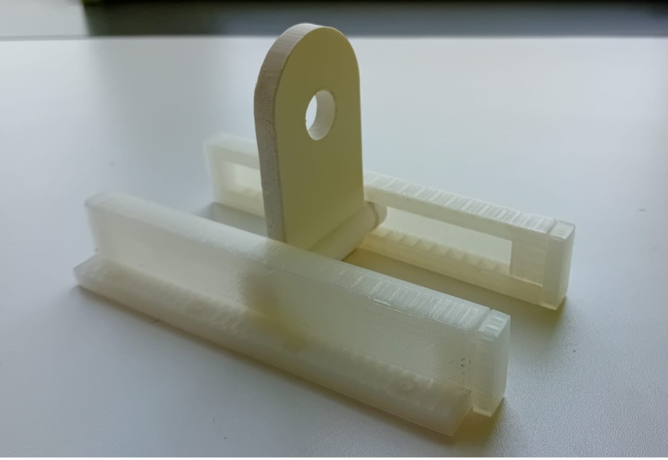
The design was split up in two parts as the length adjustment system of the egg holder provided a point of complexity in the design of the frame. These two parts are named length adjustment system and the remaining frame.
The adjustable length system was design by Sophia Döring. For any further information of the design look on her individual page. The additional requirements for this part of the frame were defined as:
- The system must be capable of adjusting to a length of 55 mm
- Tolerance for adjustment should be within 5 mm
- User-friendly
- Stability is essential to support the weight of an egg without risk of tipping
- Should withstand the forces from the spring forces (egg holder)
As design a simple rail slide system was incorporated with the functionality of rotating the slide in a way to interlock with the rail.
The design was created in Fusion360 and fabricated with 3D printing using an Ultimaker S5 and an Ender 3 v2.
The remaining frame 2.0 design was done by Frauke. In her design, time was a major factor, which is why the majority of the frame was designed to be manufactured quickly. Here, the choice of the manufacturing process fell on lasercutter.
Also, because of time-issues, the design was quite simple. In principle, consists of a baseplate, which is elevated by some 3D printed feet at the corner and some under the plate as well. This allows to attach something with bolts and nuts to the baseplate. On top of it, There are several lasercut mounts, e.g. for the two stepper motors and bearings. These are also lasercut and joined with the baseplate via finger joints. To further stabilize them, several sheets of materials are used for mounts and 3D printed angle stabilizers are used. Lastly, the rail slide for the egg holder can be mounted with several screws. The image shows the design of the frame. It accounts for kerf and the thickness of the material with parameters

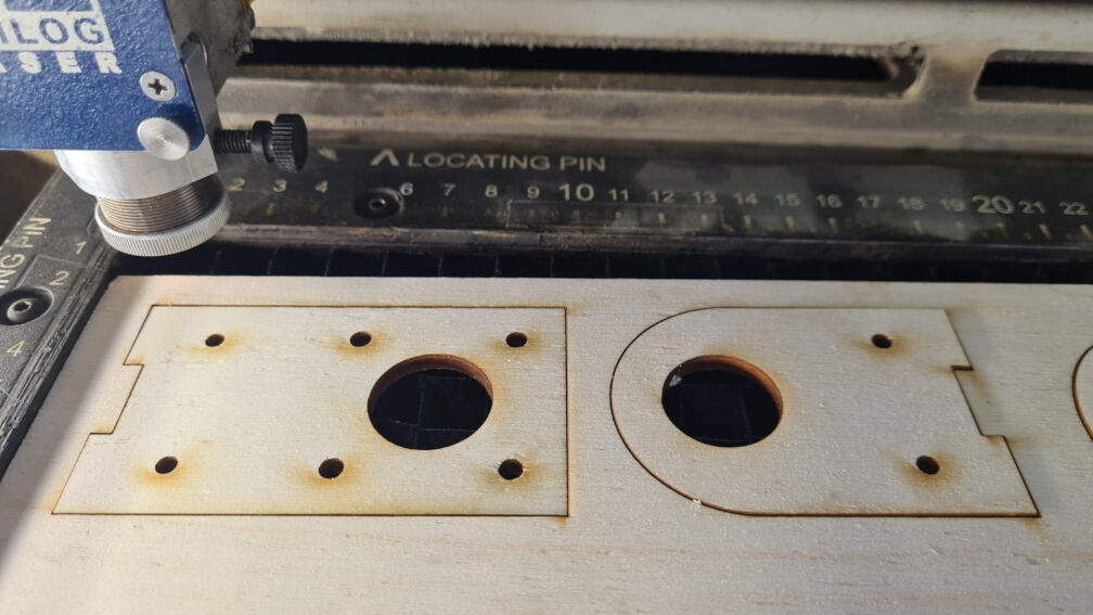
The majority of the parts were laser cut on the smaller Epilog laser in our lab with the auto-focus feature from 4mm plywood. After exporting the faces of all lasercut parts from fusion as .svg files, they were opened at the computer connected to the laser and send to the laser software as a print. In this software, the parts were cut with the vector cuts with the settings for 20 as speed, 90 as power and 17 as frequency. These are the settings we found optimal for this material during our lasercutting assignment. The value for the kerf used in the design was also taken from there.
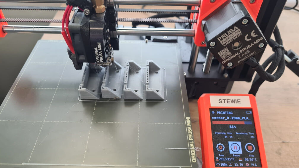
The 3D printed parts were printed on several printers at the same time to speed the manufacturing process up. In general, the bodies were exported as .stl files and imported to the slicer software. They were printed with a standard printing profiles. For the Ultimaker S5, the "Normal - 0.15 mm" profile was used and for the Prusa MK3 the "0.15mm QUALITY" profile. All parts were printed without supports
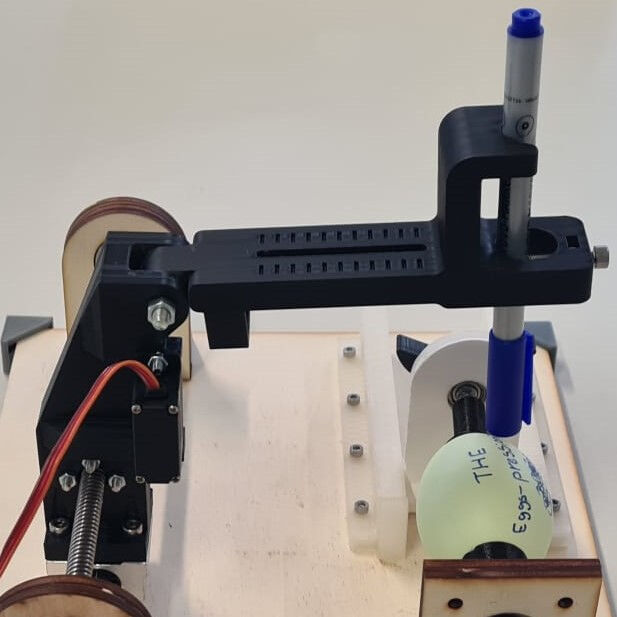
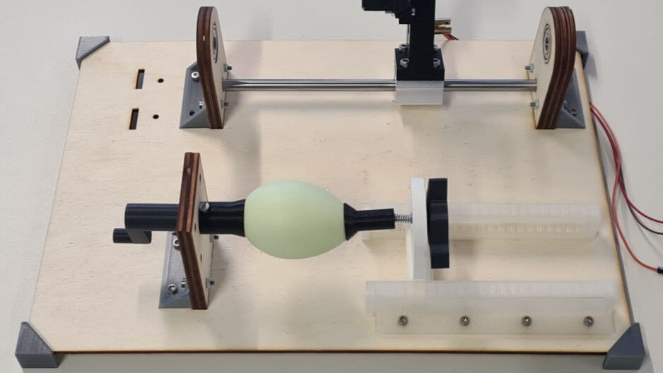
After the manufacturing, we could assemble everything. This was done by inserting the laser cut mounts onto the baseplate and fixing their position with the corner stabilizers. Next, the rail slide was mounted and lastly the feet. The photo below already shows the egg holder, the translation stage and the pen holder in place.
Working Mechanism
Electronic Design
The electronics were designed by Jona from the FabLab Bottrop. Please refer to his site for more details as below, only a summary is give.
For designing the PCB, an old Egg-Bot design from 1990 was used as a reference. The old project works on a small PIC microcontroller, and since that seems to be enough, a more modern, a lot faster dsPIC was used. For stepper drivers, the A4988 from Allegro was used since it has been used not only in the old Egg-Bot design, but also at both FabLabs involved in the project. Servo outputs were added to give the cheap servos the control voltage they need, and the whole project needed three different supply voltages - 12 to 24 volts for the steppers, 5 to 10 volts for the servo, and 3.3V for the microcontroller. Voltage regulators for 5V and 3.3V were taken from what was there, with the 5V regulators being leftovers from a FabAcademy project of one of the instructors.
The images below show the schematics and the layout of the board made with KiCAD.


A Circuit Board was designed and made, with everything the project should need and some parts (like a second servo output) to spare for growth of the machine. Milling the board worked fine. The produced board is shown below.

However, some hidden problems came up during stuffing - the microcontroller was just slightly rotated (probably when pulling the board from the hotplate), so one side of the QFN was not properly contacted. This was only found long after all the pin headers were soldered in, so going back onto the hotplate was impossible. Trying to repair this with hot air killed the microcontroller, replacing the microcontroller killed the PCB, so it will have to be redone

Right now, we are waiting for new components to arrive to make a new board like this and hopefully not killing the microcontroller.
From Manually to Automated
This part was a task for the whole group.
Evaluation of the Execution
In general, the project went really well. However, the execution was not perfect. This was due to the fact that we had planned on using certain components but instead used other components that were already available for us. This delayed the design phase and with it the other tasks as well. Therefore, in contrast to our time management (see above), we assembled the mechanical parts on Tuesday (9th of April) and not on the Monday. Similarly, the PCB design was delayed and therefore we only brought everything together on the 9th of April. However, then, the board got fried. Therefore, the complete machine is not done yet (edit from the 21st of april).
Problem Solving in a Team
In general, there were only minor issues. First of all, we were already planning on using certain parts like a linear slide and designed our parts around it until we figured out that we had similar but not the same components in the lab. This resulted among others in redesigning several if not all mechanical parts. Here, the frame had to change drastically. However, the responsible person was unavailable at this time already, which is why two of the team took over the part. This required working in parallel with good communication.
The biggest problem was probably frying the PCB on the day before we had to present the machine. To overcome this problem in a team, Jona worked with another person on fixing the PCB (we did not kno at this point that we could not rescue it) while the others worked on hardcoding several shapes to draw on the egg-bot using a pre-made PCB, a breadboard, motor drivers and jumper cables. Here, we potentially waited slightly too long with taking actions to work in parallel. Otherwise, we would not have had the time pressure later. Nevertheless, this gave us time to already do some fun side-quests like the AI-generated music and an animated video. Therefore, this was a fun activity rising the motivation and happiness of all group members.
In general, we think the group assignment worked relatively well without really much problems regarding the group's dynamic and communication. During the initial phase of working on the individual tasks, everybody communicated well such that the interfaces of the tasks were fixed fast.
Possible Improvements
Even though we are really happy with the outcome of the machine, there are some improvements that can be made.
For the pen holder and the final frame, please refer to Frauke's documentation, i.e. here and here, respectively. In summary, there was a minor issue as the pen holder allowed for some backlash when drawing on an egg and changing the direction. A possible improvement would be to include a spring or just using a perfectly round rod for the hinge of the pen holder instead of the threaded M5 nut to alleviate the present play in the joint. The frame appears to be a valid design but could be improved stability-wise for the baseplate.
Regarding improvements for the egg holder, please refer to Bianca's documentation. In general the egg holder did its job and worked well. However, the design could be improved by adding something more adhecive to the parts that were in contact with the egg, and also after observing the machine in action, I realized that the spring mechanism could have been more sturdy if it was made with a stronger material. ei: a thicker shaft as the original one was M3, maybe by using M4 would have been wiser.
We came to a conclusion on the frame design in the second attempt, but with good project planning, we could have saved time in the project by designing a frame with parts that could be produced using a laser cutting machine in the first attempt.
Design Files and Source Code for Download
- Pen Holder (.f3d): Fusion 360 file of the pen holder
- Frame (.f3d): Fusion 360 file of the frame
- Frame 1.0 (.f3d): Fusion 360 file of the frame 1.0
- Egg Holder (.f3d): Fusion 360 file of the egg holder knob
- Egg Holder (.f3d): Fusion 360 file of the egg holder