Mechanical and Machine Design
Assignments
- design a machine that includes mechanism+actuation+automation+application
- build the mechanical parts and operate it manually
- actuate and automate your machine
- document the group project and your individual contribution
Hero Shots
Initial Idea
As machine w, we embarked on a project to design an egg painter, drawing inspiration from the Sphere-O-Bot and the Eggbot, especially given the timing of our assignment, coinciding with the Easter season.
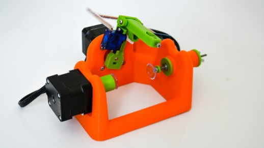
Sphere-O-Bot
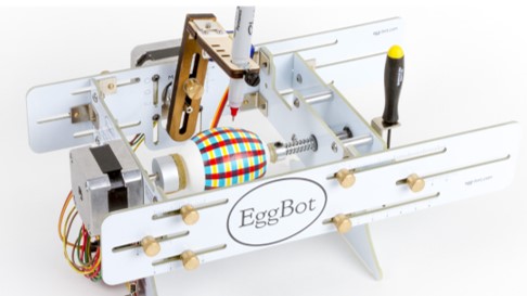
EggBot
The structure of our egg painter closely resembles that of existing models. The egg is securely fixed within a frame, akin to a piece of wood in a lathe, allowing it to rotate smoothly. Positioned atop the egg is a pen, which can also rotate to cover most of the egg's surface area. To enhance versatility, a motor facilitates vertical movement of the pen, enabling temporary removal for ink replenishment or adjustments. Additionally, a specially designed spring mechanism accommodates the egg's uneven surface and spherical shape, ensuring consistent contact between the pen and the egg.
Compared to these robots, we decided to include a linear movement of the pen holder rather then a rotational as well as create a system also include longer object to get painted.
We then identified the main tasks and parts of the robot:
- the egg holder
- the pen holder
- the frame
- the linear motion
- the electronics design
We distributed these tasks to every group members. I decided to do the linear motion for the pen holder and additionally a part of the frame, the adjustable length system for including longer objects.
Linear Motion
Requirements
At first defined requirements for the system:- The linear motion of the rail must be a translation of the rotational movement generated by a NEMA 17 stepper motor
- The linear motion rail must offer high precision to ensure accurate movement of the pen along one degree of freedom
- Smooth motion is essential to prevent any jerky movements or inconsistencies in the plotted lines.
- The linear motion rail should provide secure attachment points or mounting options to the frame
- While meeting all the necessary requirements, the linear motion rail should also be cost-effective
Design Ideas
In general, kits including a stepper motor to linear actuate axis is used in a lot of machines, like 3D printers, CNC machines, and Lasercutters. Depending on the forces and the precision the parts can differ.
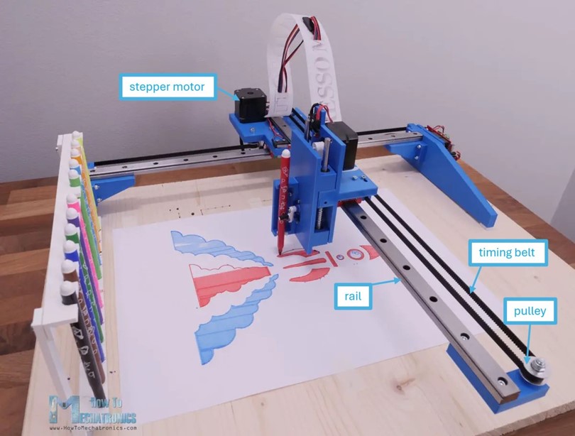
By looking at the a common diy pen plotter, the linear motion in one direction is created by stepper motor and a timing belt pulley system. The advantages of a timing belt pulley system for linear actuation include high precision, smooth operation, efficiency, low maintenance requirements, compact design, and cost-effectiveness. Additionally, the gear ration can be easily adjusted and and designed with the off-shelf existing timing belt pulley systems.
To constrain any other degree of freedom, a linear guideway, is used similar to the HIWIN-original. These rails run smoothly and achieve high precision even under load.
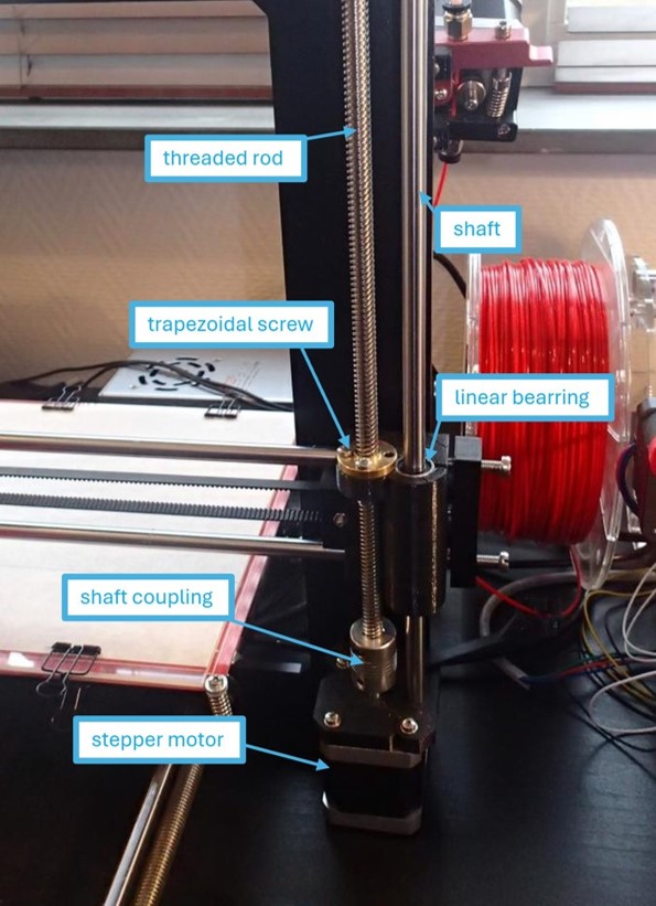
Another common system for linear translation is the use of threaded rods, frequently employed in the Z-axis movement of 3D printers. In this system, a threaded rod or shaft is connected to a stepper motor using a shaft coupler, facilitating controlled rotation. The object to be moved is affixed to a nut or trapezoidal screw that engages with the threads of the rod. As the rod rotates, the nut moves up or down along the rod, translating the object accordingly.
To ensure stability and alignment, additional degrees of freedom are constrained using shafts and linear bearings. These components support the movement of the rod and the object, minimizing lateral motion and maintaining precision. Linear bearings facilitate smooth and accurate translation by guiding the motion along the rod, reducing friction and ensuring consistent performance.
Overall, the threaded rod system provides a cost-effective and reliable method for linear translation, particularly suitable for applications such as 3D printing, CNC machines, and other automated systems requiring vertical movement.
As the forces and precision needed for the egg plotter are similar to the one of a pen plotter or a 3D printer. I decided to design a system that is using the rail and the threaded rod. The main reason for not using the timing belt pulley system are the costs of the parts.
Design
I have opted for a 1:1 gear ratio in coupling a stepper motor to a rod, utilizing a slide as a constraining component to minimize material usage for the frame. Unlike a shaft, which would require additional support structures, mounting the rail directly on the ground offers the advantage of reducing the need for extra support.
The design of the linear motion system was done in Fusion 360. As no customized parts are needed for that system, I used the library for standardized part included in Fusion.
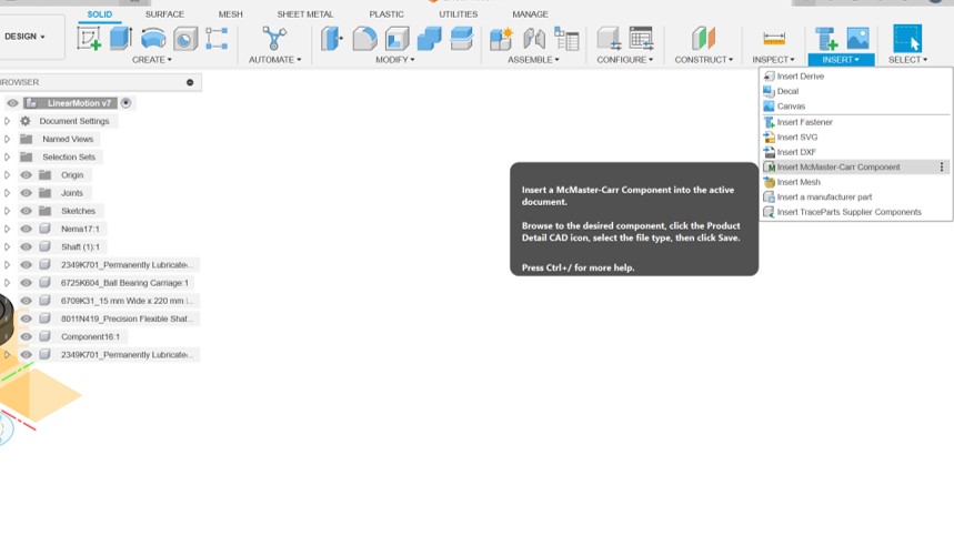
Go to "Insert" and click on "Insert McMaster-Carr Component".
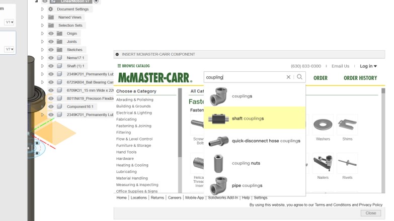
Search for your component in the searchbar.
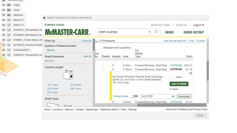
Find the right dimensions for the component and download a .stp file.
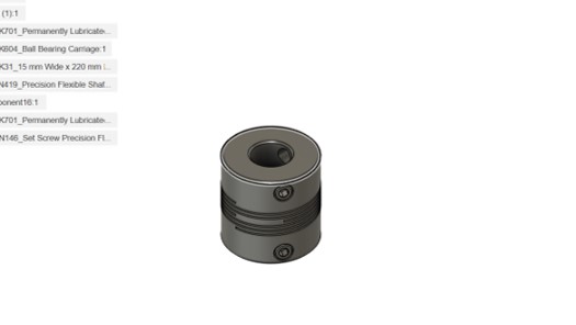
You then can insert the part to your Fusion 360 workspace.
To make sure everything is correctly aligned and all components have the right size. It can help to join them together.
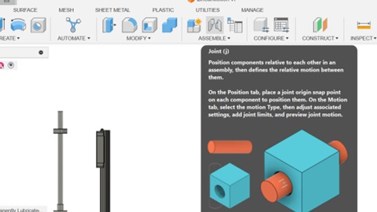
To create a joint click on "Joint" in the "Assembly" segment (press J) and choose the components you want to join
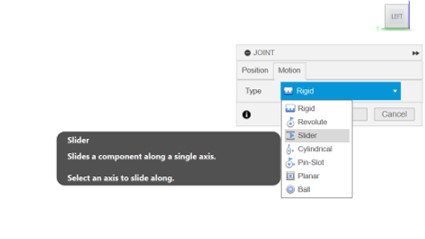
In the second tab you can choose the type of joint you want to use.
The finished system included all parts needed for the linear motion of the pen holder.
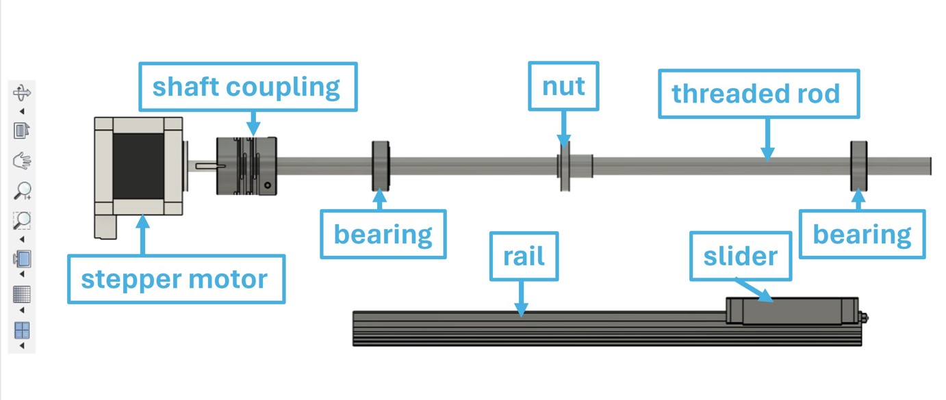
List of Materials
| Amount | Part | Description | Link |
|---|---|---|---|
| 1 | Trapezoidal spindle with nut | T8, length = 300mm | HERE |
| 1 | shaft coupling (flexible) | Adaption: 5mm to 8mm | HERE |
| 1 | linear slide | MGN15H length 200mm | HERE |
| 2 | Bearings | USS 608 2RS TN GF1 8x22x7 mm | HERE |
| 1 | NEMA 17 | ACT Nema 17 Schrittmotor 17HS4417 2.6V 1.7A 40mm | HERE |
| 10 | pan-head bolts | pan-head bolts M3x10, for linear slide mounting | HERE |
| 4 | sockets-head bolts | sockets-head bolts, DIN 912 A4 M3.5X10, for spindle nut | HERE |
| 4 | nuts | M3.5 | HERE |
Changes
Utilizing resources available in the lab, I opted to incorporate a linear bearing and shaft to constrain the degrees of freedom. I proceeded by reverse-engineering the critical dimensions of both the linear bearing and the shaft, were they would be connected to the penholder and the frame.
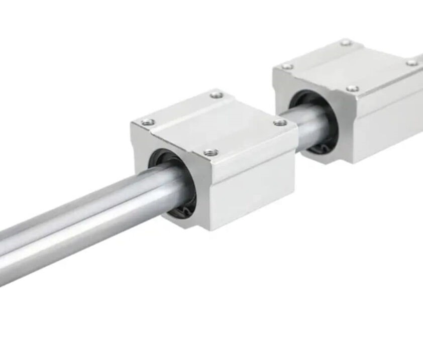
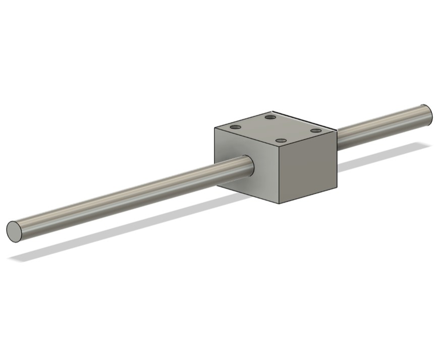
Adjustable Length System
Requirements
Firstly, I defined the requirements for the design:
- The system must be capable of adjusting to a length of 55 mm
- Tolerance for adjustment should be within 5 mm
- User-friendly
- Stability is essential to support the weight of an egg without risk of tipping
- Should withstand the forces from the spring forces (egg holder)
Design Ideas

One of the possibility to adjust the length can be find in the EggBot. The Eggbot design features adjustable nuts for smooth length adjustments, offering precision and stability to securely hold the egg in place. However, a drawback lies in its user-friendliness, as the process requires adjusting three nuts to change the length, which may be cumbersome for users.
One of the initial concepts was to incorporate two slots on the bottom of our machine and utilize two nuts for adjusting the length. This method involves loosening and then tightening the nuts to achieve the desired length. While it can offer good precision, the handling may not be user-friendly.

An alternative approach involves utilizing standard aluminum profiles with fixed T-nuts. These T-nuts are securely attached within the aluminum profile, preventing movement when turned sideways. This method offers simplicity and ease of use compared to adjusting multiple nuts individually.
Typically, standard aluminum profiles and T-nuts are commonly used in various applications such as framing systems, machine guarding, workstations, and automation equipment. They provide a versatile and modular solution for constructing structures and fixtures in industrial, commercial, and even hobbyist settings due to their lightweight, durable, and easily configurable nature.
However, this solution tends to be less cost-efficient and may be considered over-designed for the forces exerted on the part.

The latest idea involves implementing a slide and stop system. One of the sockets required to secure the egg can be rotated downwards, allowing for movement, and then interlocked into the rail when perpendicular to the ground.
I design a small test for the fit and 3D-printed it. I incorporated a tolerance of 0.2 mm for the sliding and interlocking. Therefore, this is also the one I used for the final design.
Design
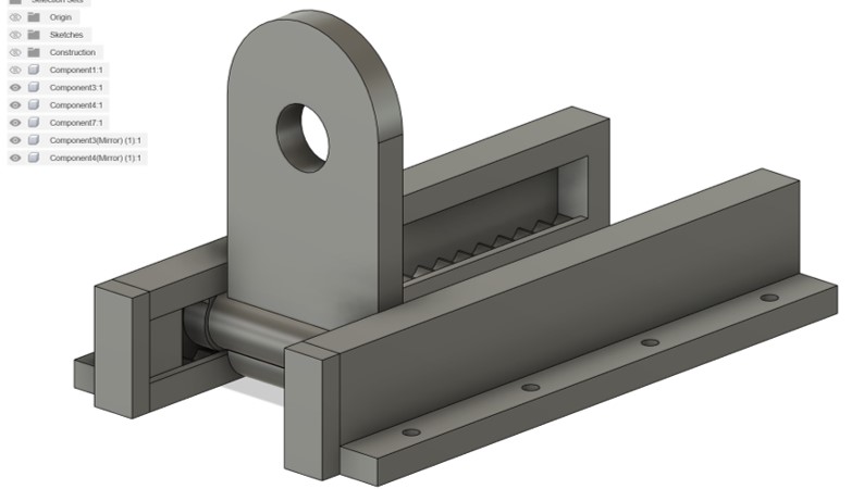
After that I design the the total system. I designed everything to be 3D printed.
I started with one rail. The structure to interlock with the slide from the socket is inserted into the rail, the structure around the rails constraints any other degrees of freedom.
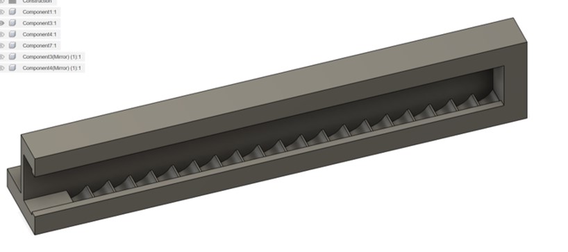
Later, I designed the socket to connect with one of the egg holders using a bearing, incorporating a 0.1 mm tolerance for a tight fit.
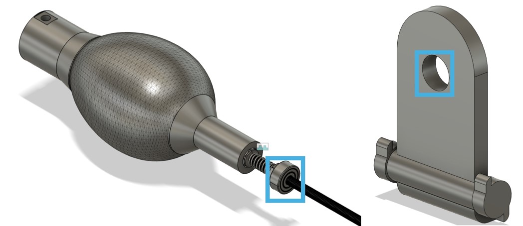
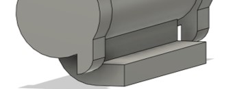
To constrain the movement and rotation of the socket, I included this stopper into the design
Next, I developed a component for the open end of the rail, ensuring it secures the slide inside the
rail upon insertion and constrains the sliding movement to precisely 55 mm.
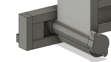
As the rail needs to be mounted to the frame on the ground, I included four screw holes for M3.5 bolts.
Fabrication
I 3D printed the parts on the Ultimaker S5 and the Ender 3 v2.
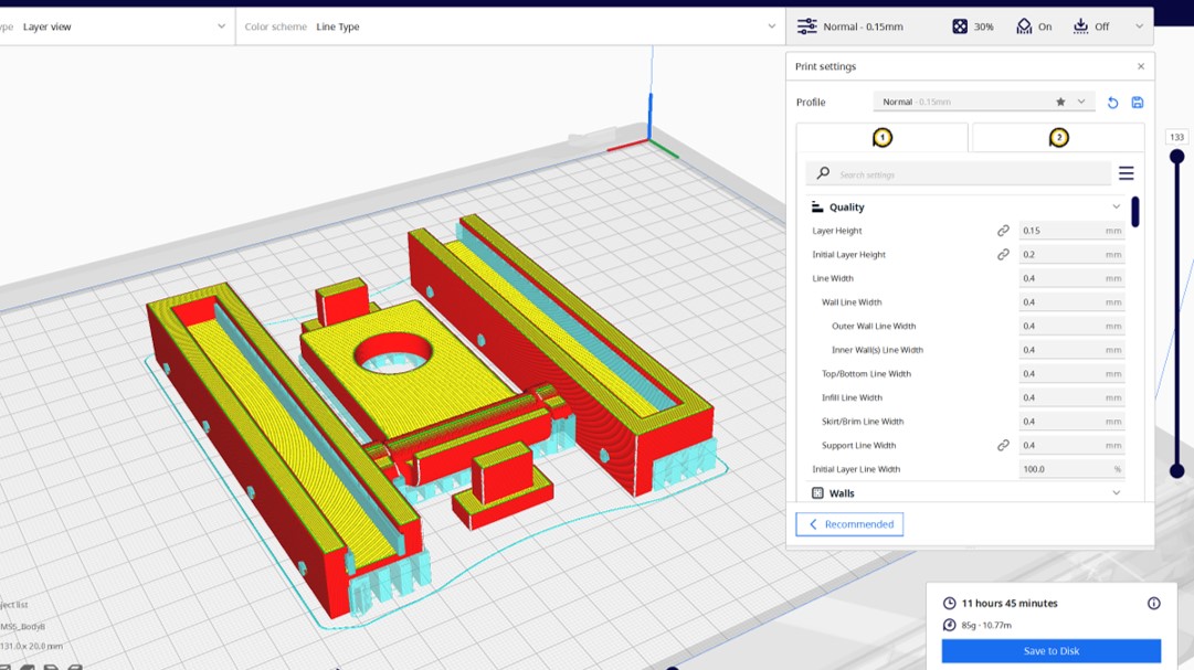
For the first print the Ultimaker S5 including was utilized all parts of the AL system. Cura was used as Slicer Software. The initial print took 11 h and 45 min. The quality was set to 0.15 mm.
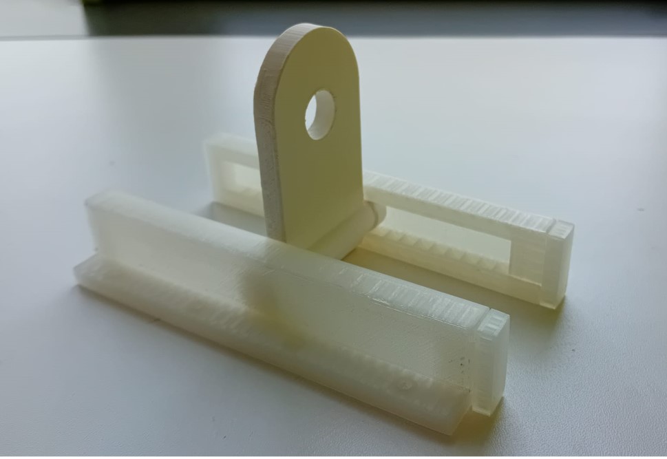
We mounted the rails on the frame and the egg holder to the socket.
Side-Quest
As part of our assignment, which also involves creating a one-minute video showcasing our project, we opted to incorporate a song to provide background narration about our work. To this end, I requested ChatGPT to compose a rap song encapsulating our journey. The theme of the song revolves around Neil Gershenfeld assigning us the task of creating a machine, which led our group to choose an egg painter machine as our project. Subsequently, we successfully designed and constructed the machine as per our assignment. The output was this:
(Verse 1)
Listen up, y'all, let me tell you 'bout a dream,
Neil Gershenfeld sparked it, and we joined the team.
Assignment on the table, had to make a machine,
So we put our heads together, cooked up something keen.

Egg painter machine, that was our call,
Innovation on display, gonna stand tall.
Gonna crack some shells, let the colors flow,
With precision and style, watch our creativity grow.

(Chorus)
Egg painter machine, it's our pride and joy,
From the mind of Gershenfeld, we deploy.
Putting art on shells, that's our mission,
With our rap game strong, we're on a creative mission.

(Verse 2)
Got the gears turning, got the motors spinning,
In the lab all day, ain't no time for quitting.
Designing, coding, wiring up the scene,
Every step we take, feels like we're living the dream.

Egg after egg, we're painting masterpieces,
From intricate designs to colorful releases.
Neil's assignment got us feeling so alive,
With our egg painter machine, we're gonna thrive.

(Chorus)
Egg painter machine, it's our pride and joy,
From the mind of Gershenfeld, we deploy.
Putting art on shells, that's our mission,
With our rap game strong, we're on a creative mission.

(Bridge)
Gonna show the world what we can do,
With our egg painter machine, we'll break through.
From the lab to the stage, gonna make some noise,
Turning eggs into art, that's our choice.

(Outro)
So here's to Gershenfeld, for the inspiration,
And to our egg painter machine, our creation.
Rapping 'bout eggs, yeah, that's how we roll,
With our machine and our rhymes, we're on a creative stroll.
I used suno.ai to make a rap song out of this lyrics.
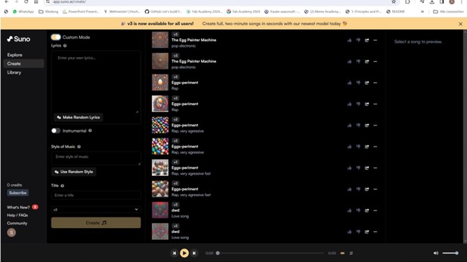
Go to "Create" and enable "Costum".
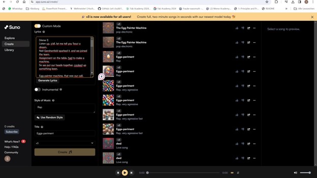
Paste your lyrics into the program, and decide for a style.
... and it did an amazing job.
Unfortunately, the webpage only produces 2 min of a song for free. Therefore, the end is very abrupt.