10. Mechanical design and machine design
During this two weeks I worked together with the students from fablab Kamp-Lintfort. Information about the project you will find on their group site and on the student sites.
What I have done
After the meeting on Thursday during which we defined the project and assigned tasks, I started to learn more about the eggbot. A lot of eggbots has been build during the last 34 years. Most of the information I found was about building the machine with Arduino. The texts and videos were good to understand how such a machine can be built and how it can work. It also helped to find out which components are needed to build the electronics.
The next goal was to find out which other microcontrollers had already been used to build the machine. I came across the EggBot from 1990, which was built with a PIC from Microchip. You can find the electronics for it here. Since there was no microcontroller available that was compatible with marlin and that I had already worked with, I decided to see if one of the PICs available met the requirements. Since this was the case, I decided to work with it. Stepper drivers were selected by using what had already been used at the fablab, a cheap and common chip called A4988.
The first step in drawing the PCB was to find the required data sheets for the PIC and the drivers for the motors. Then I made a quick sketch of the plan and discussed it with my instructor.
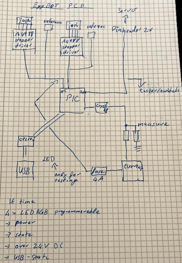
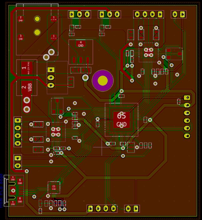
I then converted the circuit diagram into KiCad and added the necessary components such as resistors and capacitors. After that my instructor reviewed this again.

The layout was a little more difficult. On the one hand, the PCB should not be so large, on the other hand, the layout should not take too much time and the assembly should not be too complex. At the same time, it was necessary to work with traces of different widths. In addition, the stepper drivers are actually designed for a four-layer PCB layout. As we do not have galvanic in the FabLab, this was not feasible for us and 2 layers had to suffice.
After my instructor also checked the layout and we changed a few areas, I milled the board with the board milling machine we have available in the FabLab. I then cleaned the board and inserted rivets using a rivet press. To protect the board a little better, I sprayed it with protective varnish on both sides.
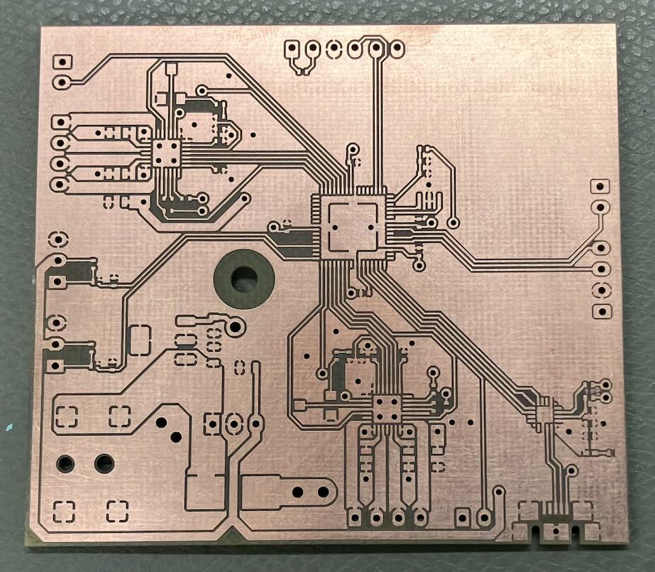
Unfortunately, as has already been shown with previous PCBs, the solder does not adhere so well to the paint and soldering becomes unnecessarily difficult. The lacquer was therefore removed from the pads to be soldered and solder paste was applied to the pads with a needle. The board was then assembled as usual and soldered with the hotplate.

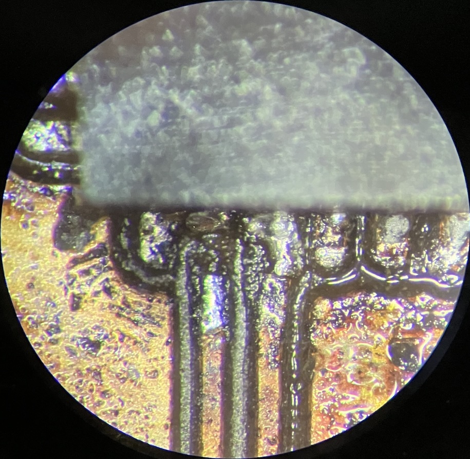
The next step was to look at the board under a microscope and remove faults such as solder bridges. It was then measured to find other faults. A multimeter was used for this. The faults found were also rectified.
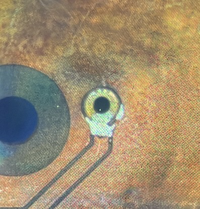
Unfortunately, when trying to program the microcontroller, it became apparent that there must be other, previously invisible errors. It then became apparent that the microcontroller had slid marginally on the PCB and therefore had almost no connections on one side - The side with the programming port.
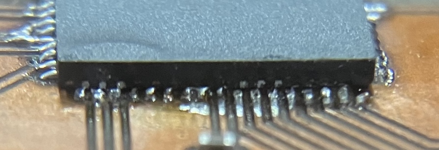
Unfortunately, correcting this (using a hot air station, since the board already had the pinheaders soldered in) did not bring any improvement. After other boards that we had and that were already working also threw the same error message, the programmer was checked to see if it was OK. The programmer was OK, but it also meant that the error was still not found. The next step was to replace the microcontroller in case it had overheated during correction. This was done using hot air, again, and did not improve things, again. At the same time, the error on the other board was found and fixed, so the programmer was now known to really be OK. A good microscope turned up the (new) error on the PCB, in the form of two ripped off tracks - Again, the ones of the programming port.
Any attempt to fix this with really thin wire just ripped off more of the tracks, so this board will have to be rebuilt.