Networking and Communcations
Assignments
All the important links are Here
Learning outcomes
Vocabulary
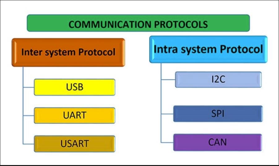
Inter-System Protocol
What it is: Inter-system protocol is like a set of rules that different devices use to communicate with each other.
Why it matters: Imagine if you have a smartphone and want to send a message to a friend's computer. The inter-system protocol helps your phone (using apps like WhatsApp or Facebook Messenger) and their computer (using a web browser or messaging app) understand each other's messages. It's like having a common language for devices from different brands or using different software to talk to each other over the internet.
Examples: HTTP (used by web browsers to load websites), TCP/IP (helps computers connect to the internet), and Bluetooth (for wireless headphones connecting to your phone) are examples of inter-system protocols.
Intra-System Protocol
What it is: Intra-system protocol is like rules that different parts inside one device use to communicate with each other.
Why it matters: Inside your smartphone or computer, there are many parts like the screen, memory, and processor. The intra-system protocol makes sure all these parts work together smoothly. It's like having a way for all the different parts inside your device to understand each other and do their jobs properly.
Examples: SPI (used for communication between microchips inside devices like Arduino), I2C (helps sensors and microcontrollers share information), and UART (used in devices like GPS modules and Bluetooth adapters) are examples of intra-system protocols.
Communication Protocol:
A communication protocol is like a set of rules that devices follow when they talk to each other. Imagine you're playing a game with your friend, and you need to agree on some rules before you start. That's what a protocol does – it makes sure devices understand each other and know how to send and receive messages.
Node:
A node is just a fancy word for any device that's part of a network. It could be your computer, your phone, or even a printer. Think of nodes as the players in a game of tag – each one can send messages to other nodes, just like players can tag each other in a game.

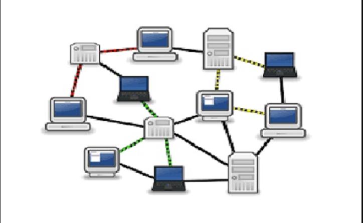
Network:
Think of a network as a big web of connected devices. It's like a big family where everyone knows each other and can talk to each other. Networks can be small, like the ones in your home, or huge, like the internet that connects people all over the world.
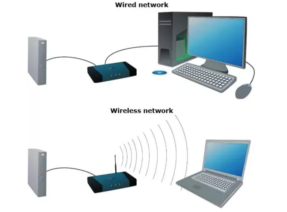
Wired Communication:
Wired communication involves sending messages through physical cables or wires. It's like sending letters through the mail – you put your message in an envelope and send it through a postal service. Similarly, devices connected by cables can send data directly to each other without any interference. Wired communication offers reliability and stability, making it suitable for applications where consistent and high-speed connectivity is essential, such as in homes, offices, and data centers.
Wireless Communication:
Wireless communication allows devices to talk to each other without needing physical cables. Instead, they use invisible signals called radio waves to send messages through the air. You've probably used Wi-Fi to connect to the internet or Bluetooth to pair your phone with headphones – those are both examples of wireless communication. Wireless communication provides flexibility and convenience, allowing devices to communicate without physical constraints. It's widely used in various applications, including Wi-Fi for internet access, Bluetooth for connecting devices like headphones and speakers, and Zigbee for home automation and IoT deployments.
Bus Address:
Imagine a big school bus with lots of seats. Each seat has a number so the driver knows where each student needs to get off. In a computer network, a bus address is like those seat numbers – it helps devices know where to send their messages so they reach the right place.
Group Assignment
Networking and Communication
The group assignment includes communication as everything in this week.
Send a message between two projects
Document your work to the group work page and reflect on your individual page what you learned.
Introduction
This week we have to communicate between two projects. This communication can either be wired or wireless.
Work Plan
For us to proceed with this assignment, we need to have a plan! So let's get right into it and start with our group assignment.
Since we have to communicate between two projects, we must have to whether set up a wired communication that is using one of the wired communication protocols. If not that, we can also do wireless communication through either Wi-Fi or Bluetooth. There was a long discussion between the five of on whether to wired communication or wireless communication. After the discussion was over, we ultimately decided to use the wireless communication protocol for our group assignment.
Materials Needed
- ESP 32 C3 XIAO - The esp 32 c3 xiao board is a powerful and compact board that has the capabilities of doing wireless communication through Wi-Fi.
- USB Cable type C - The USB type C also are needed as the esp 32 c3 xiao boards have to be programmed through the very cable.
TCP - Transmission Control Protocol
After we got the materials, we have to get to a bit more about how we are actually going to communicate wirelessly. The ESP 32 C3 XIAO has a built-in Wi-Fi module so we went with a form of communication that uses Wi-Fi to communicate between the two boards.
Transmission Control Protocol (TCP) is a core protocol of the Internet Protocol Suite (TCP/IP) that enables reliable communication between devices over a network. TCP ensures that data sent from one device arrives intact and in the correct order at the destination device.
Establishing a TCP Connection
The process begins with a three-way handshake to establish a connection. The device initiating the connection, known as the client, sends a TCP packet with the SYN (synchronize) flag set to the server.
The server responds with a TCP packet that has both the SYN and ACK (acknowledgment) flags set.
Finally, the client sends an ACK packet to the server, acknowledging the connection establishment. At this point, the connection is established, and data transfer can begin.
Sequence and Acknowledgment Numbers
During the connection establishment, both devices exchange initial sequence numbers, which they use to identify and order the data packets sent.
Each TCP packet sent includes an acknowledgment number to inform the sender of the next expected sequence number. This ensures that packets are received and processed in the correct order.
Overall, TCP, or Transmission Control Protocol, is a set of rules that allows devices to talk to each other over the internet. It works by establishing a connection between two devices, ensuring messages are sent and received in the right order, and making sure nothing gets lost along the way.
Setting Up
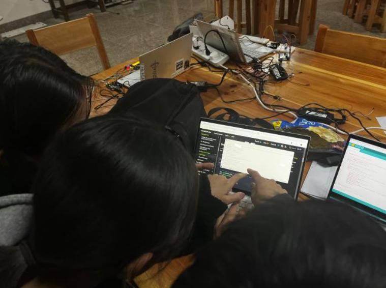
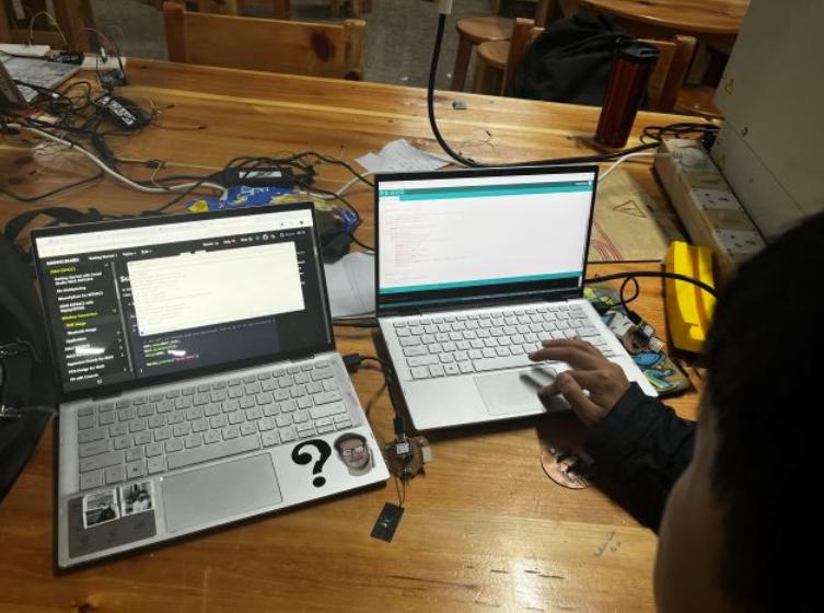
Now lets finally start with our group assignment! Now after we are done with all the theoretical processes of the project, we can now finally start up with practical bits of the assignments.
Firstly let's start with setting up 2 laptops to program our xiao boards. We would also need two xiao boards so that we start with Wi-Fi communication. Before doing this we also referred to the documentation that was in the Seed Studio WIKI page.
Setting up the boards
We first have to get two xiao boards ready. We used Thinley and Damzangs board for this assignment as not only were they were only ones the that were using the ESP32 C3 XIAO microcontroller and had made boards for them.
Then after that we have to insert the antenna that comes with the microcontroller and then insert it the slot that is supposed for the antenna.
Coding
Now after inserting the antennas onto the boards we can start programming our boards and then start with this week's assignments
After we set up our boards, we have to write our code. we first wanted to create only a simple code that would be print "button pressed" from one of the xiao boards(Thinley's board) when a button on another board(Damzang's board) is pressed. In addition, we also made it so that pressing a button on Damzang's Board would make a LED light up on Thinley's board.
Thinley's board(client board)
            #include <WiFi.h>
            #include <WiFiClient.h>

            const char* ssid = "ESP_AP";
            const char* password = "123456789";
            const char* host = "192.168.4.1"; // IP address of the server

            WiFiClient client;

            void setup() {
              Serial.begin(115200);
              pinMode(5, OUTPUT);

              Serial.println();
              Serial.println("Connecting to WiFi");
              WiFi.begin(ssid, password);

              while (WiFi.status() != WL_CONNECTED) {
                delay(500);
                Serial.print(".");
              }

              Serial.println("");
              Serial.println("WiFi connected");
              Serial.println("IP address: ");
              Serial.println(WiFi.localIP());
            }

            void loop() {
              if (!client.connected()) {
                Serial.println("Connecting to server...");
                if (client.connect(host, 80)) {
                  Serial.println("Connected to server");
                } else {
                  Serial.println("Connection failed");
                  delay(5000);
                  return;
                }
              }

              if (client.available()) {
                String message = client.readStringUntil('\n');
                Serial.println("Message received from server: " + message);
                if (message.equals("ButtonPressed")) {
                  digitalWrite(5, HIGH);  // Turn on the LED
                  delay(1000);  // Keep the LED on for 1 second
                  digitalWrite(5, LOW);  // Turn off the LED
                }
              }
            }
Damzang's board(host board)
            #include <WiFi.h>
            #include <WiFiClient.h>

            const char* ssid = "ESP_AP";
            const char* password = "123456789";

            WiFiServer server(80);
            WiFiClient client;

            const int buttonPin = 3;  // Define the pin connected to the button
            bool buttonState = false;

            void setup() {
              Serial.begin(115200);
              pinMode(buttonPin, INPUT);
              WiFi.softAP(ssid, password);
              server.begin();

              // Print the IP address of the access point (server)
              Serial.print("Server IP address: ");
              Serial.println(WiFi.softAPIP());
            }

            void loop() {
              if (!client.connected()) {
                client = server.available();
                if (client) {
                  Serial.println("Client connected");
                }
              }

              if (client.connected()) {
                if (client.available()) {
                  String message = client.readStringUntil('\n');
                  Serial.println("Message received: " + message);
                  if (message.equals("ButtonPressed")) {
                    buttonState = !buttonState;  // Toggle LED state
                    digitalWrite(buttonPin, buttonState ? HIGH : LOW);  // Control the LED
                    Serial.println("LED state changed");
                  }
                }
              }

              if (digitalRead(buttonPin) == HIGH) {
                client.println("ButtonPressed");
                delay(1000);  // Debouncing delay
              }

              printWiFiInfo(); // Print host WiFi information
            }

            void printWiFiInfo() {
              Serial.print("Host Name:");
              Serial.println(WiFi.softAPgetHostname());
              Serial.print("Host IP:");
              Serial.println(WiFi.softAPIP());
              Serial.print("Host IPV6:");
              Serial.println(WiFi.softAPIPv6());
              Serial.print("Host SSID:");
              Serial.println(WiFi.SSID());
              Serial.print("Host Broadcast IP:");
              Serial.println(WiFi.softAPBroadcastIP());
              Serial.print("Host mac Address:");
              Serial.println(WiFi.softAPmacAddress());
              Serial.print("Number of Host Connections:");
              Serial.println(WiFi.softAPgetStationNum());
              Serial.print("Host Network ID:");
              Serial.println(WiFi.softAPNetworkID());
              Serial.print("Host Status:");
              Serial.println(WiFi.status());
              Serial.print("Server IP address: ");
              Serial.println(WiFi.softAPIP());
              delay(1000);
            }
How WiFi and TCP/IP Communication Works
WiFi Setup
Each ESP32 C3 XIAO board can connect to WiFi, just like your phone or laptop. One board sets up its own WiFi network, and the other joins it, similar to how your devices connect to your home WiFi.
Client-Server Setup
-
Server (Host Board)
One board acts as the host, setting up a WiFi network and waiting for the other board to connect. It listens for messages and reacts accordingly, like turning on a light when it receives a specific command.
-
Client (Client Board)
The other board acts as the client, joining the WiFi network set up by the host board. It sends messages, like when a button is pressed, and waits for responses from the host board.
How They Talk (TCP/IP Protocol)
TCP/IP is a set of rules they follow to ensure messages are sent and received correctly:
- They start by saying "Hi" to each other (SYN).
- Then they confirm receipt with "Hi, got your message" (SYN-ACK).
- Finally, they acknowledge the message with "Got it, thanks" (ACK).
Example
For instance, when the client board (like Thinley's Board) presses a button, it sends a message to the host board (like Damzang's Board). The host board reacts by performing an action, such as turning on a light, and sends a confirmation back to the client board.
Conclusion
In summary, these ESP32 C3 XIAO boards communicate wirelessly using WiFi and follow TCP/IP rules to ensure reliable message exchange. This setup is essential for devices that need to communicate without physical connections, such as in smart home systems or remote controls.
With that, we are finally done with this week's group assignment. We learned a lot from this week's assignment, including planning, integration, and testing of our codes. Proper planning is crucial for the smooth execution of projects, and it is also important to learn from mistakes along the way. Though for this week, this is it.
Individual Assignment
For this assignment, I used the board I redesigned during week 9 and was initially designed in week 8
Wireless Communication
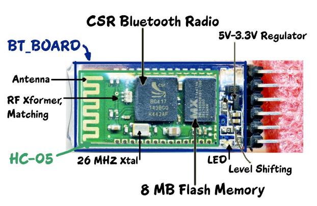
HC-05 Bluetooth Module
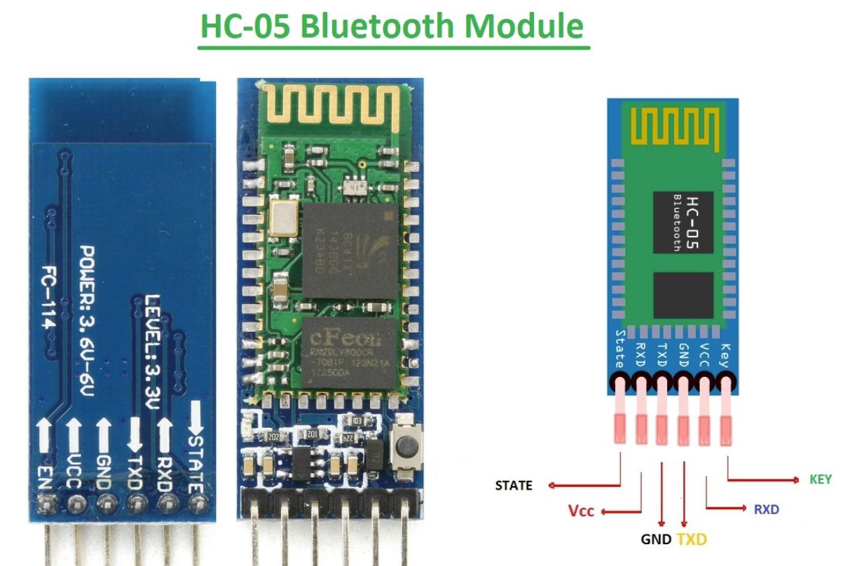
Serial communication means sending data one tiny piece at a time, like sending letters one letter at a time instead of the whole word at once. It's like how you send a text message on your phone – each letter goes out one after the other, in order.In contrast, parallel communication sends several pieces of data all at once, like speaking multiple words at the same time. This requires more wires or channels to carry all the data simultaneously.So, when we say Bluetooth uses serial communication, it means it sends and receives data one small chunk at a time, making it suitable for wireless communication between devices like your phone and a Bluetooth speaker.
I refered to this Controlling led using HC-05 bluetooth module and successfully controlled a led using the HC-05 bluetooth module
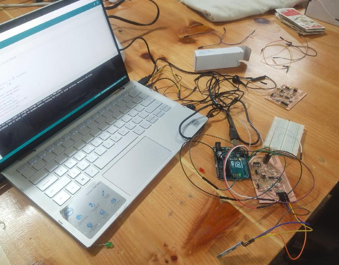
I am using the board I designed during the Embedded programming week.

The connection is simple:
Then upload the following code
The code below is chatgpt generated, and given below is the prompt I used to generate the code
                char Incoming_value = 0;

                void setup() {
                  // put your setup code here, to run once:
                  Serial.begin(9600);
                  pinMode(8, OUTPUT);
                }

                void loop() {
                  // put your main code here, to run repeatedly:
                  if (Serial.available() > 0) {
                    Incoming_value = Serial.read();
                    Serial.print(Incoming_value);
                    Serial.print("/n");
                    if (Incoming_value == '1')
                      digitalWrite(8, HIGH);
                    else if (Incoming_value == '0')
                      digitalWrite(8, LOW);
                  }
                }
Explanation of Arduino Code
char Incoming_value = 0;
This line declares a variable named Incoming_value of type char (character) and initializes it to 0.
void setup() {
This line begins the setup() function, which is called once when the Arduino is powered on or reset.
Serial.begin(9600);
This line initializes serial communication at a baud rate of 9600 bits per second. It allows the Arduino to communicate with other devices (like a computer) via the USB port.
pinMode(13, OUTPUT);
This line configures pin 8 of the Arduino as an output.
}
This curly brace marks the end of the setup() function.
void loop() {
This line begins the loop() function, which runs continuously after the setup() function has finished executing.
if (Serial.available() > 0) {
This line checks if there is data available to read from the serial port. If there is data available, the condition evaluates to true.
Incoming_value = Serial.read();
If data is available, this line reads a single byte of data from the serial port and stores it in the Incoming_value variable.
Serial.print(Incoming_value);
This line prints the value of Incoming_value to the serial port. It sends the character representation of the value.
Serial.print("\n");
This line prints a newline character to the serial port.
if (Incoming_value == '1')
digitalWrite(8, HIGH);
else if (Incoming_value == '0')
digitalWrite(8, LOW);
These lines check the value of Incoming_value. If it is equal to the character '1', pin 8 is set to HIGH (turning on the LED). If it is equal to the character '0', pin 8 is set to LOW (turning off the LED).
}
This curly brace marks the end of the loop() function.
}
This curly brace marks the end of the program.
Upload the code and then download the mobile app "ARDUINO BLUETOOTH CONTROLLER"
The Arduino Bluetooth Controller app allows you to control Arduino projects wirelessly via Bluetooth. It typically involves creating a Bluetooth interface on your Arduino and using a mobile app to send commands or data to the Arduino wirelessly.
I ahve download the applictaion from Google play store
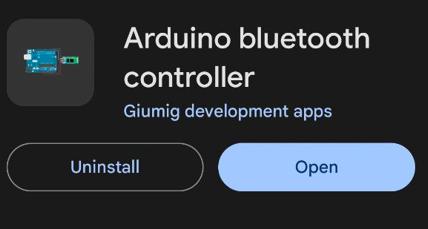
Download the above application
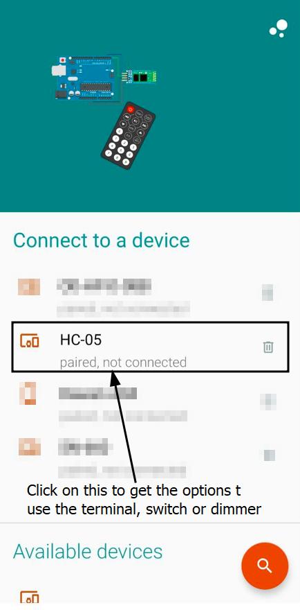
Turn your "BLUETOOTH ON" on your device, and pair with the HC-05, the passkey is usually "0000" or "1234" and then click on HC-05.
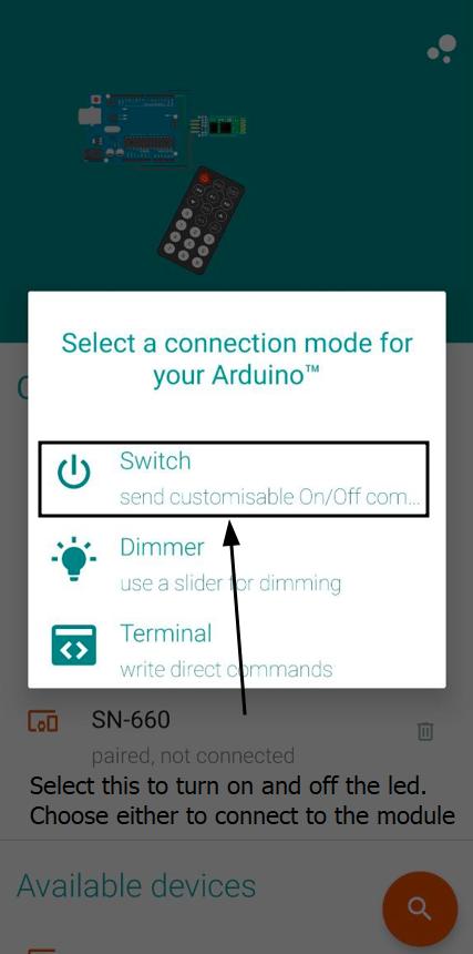
Then you will have to choose a connection mode to connect, the available connection modes are : Dimmer, Switch and Terminal.
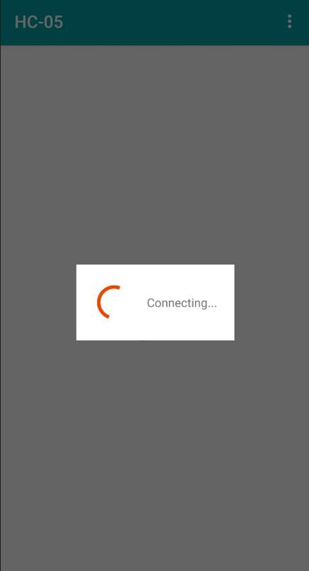
Let it successfully connect to the module.
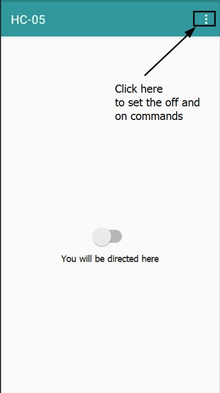
You will be directed to this display for which you will have to configure what the turned on switch is and what the turned off switch. To do that, click on the 3 dots on the topmost screen.
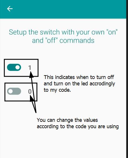
Then set the commands for the turned on and turned off switch. In my code I have the code,
if (Incoming_value == '1')
digitalWrite(8, HIGH);
else if (Incoming_value == '0')
digitalWrite(8, LOW);
in which you can see that if the incoming value is 1 then the digitalWrite is (8, HIGH) for which the "HIGH" in digitalWrite(8, HIGH); means setting pin 8 to its highest voltage level, typically 5 volts, turning it on or providing power. In simple digitalWrite(8, HIGH); turns on (sets to HIGH) the LED connected to pin 8.
And else if incoming value is 0 the the digitalWrite is (8,LOW) for which the "LOW" in digitalWrite(8, LOW); means settin pin 8 to its lowest voltage level, turning it off. In simple digitalWrite(8, LOW); turns off (sets to LOW) whatever is connected to pin 8.
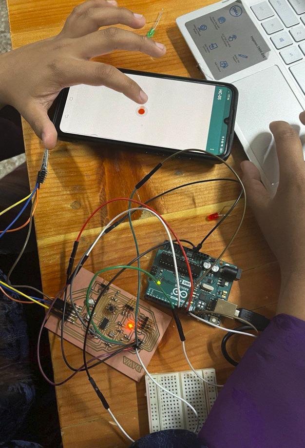
After the above steps, I was successfully able to control the led on my board!
Wired Connection
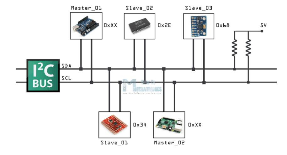
I2C (Inter-Integrated Circuit) is a communication protocol for electronics that enables devices like microcontrollers and integrated circuits to exchange data. It uses just two wires: SDA (Serial Data Line) for transferring data and SCL (Serial Clock Line) for timing. Each device connected to the bus has its own unique address, which prevents communication conflicts. I2C is ideal for connecting multiple devices over short distances with minimal hardware requirements. It's commonly used in sensors, displays, and memory modules for efficient and reliable communication.
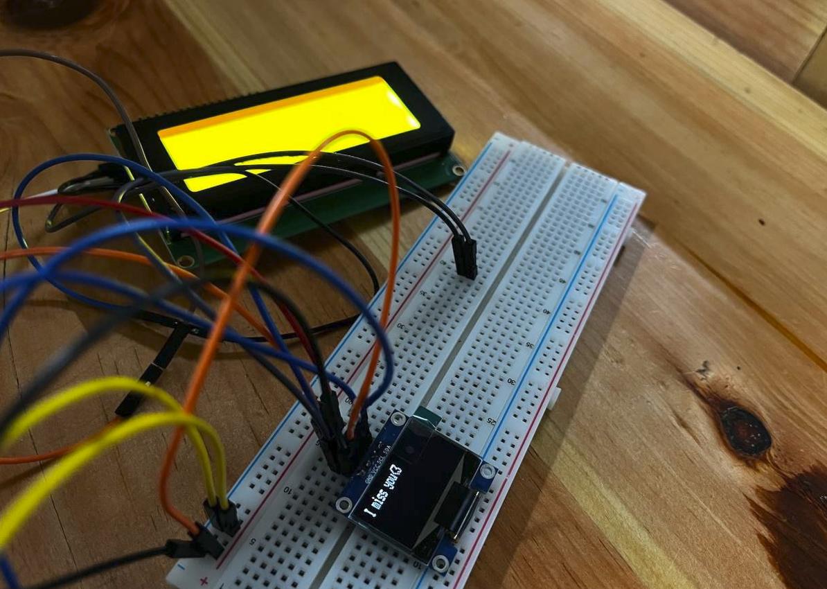
For the wired communication, I have decided to control an oled and a 20x4 i2c lcd through the same pins; SDA and SCL which follows the Inter-Integrated Circuit protocol.
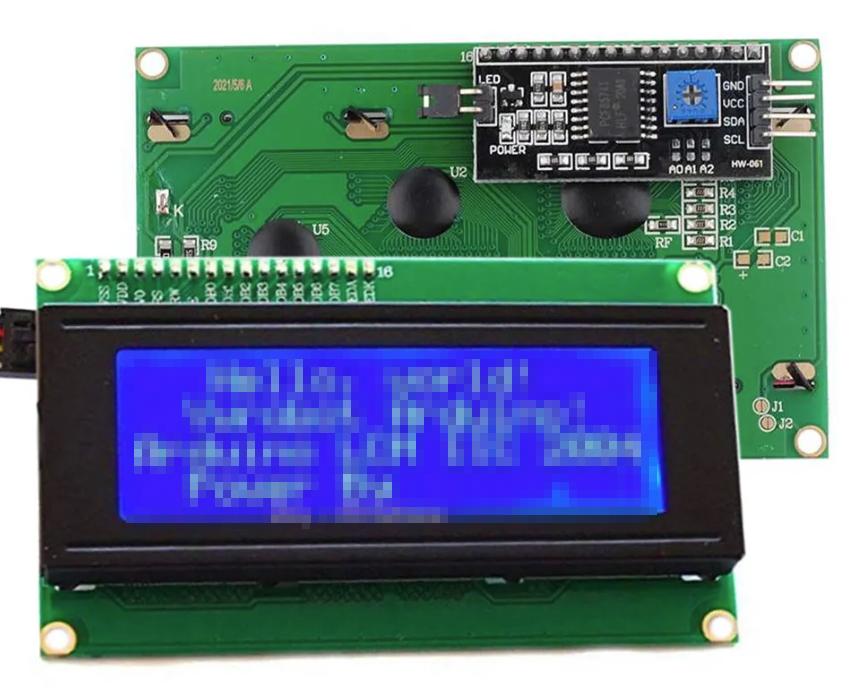
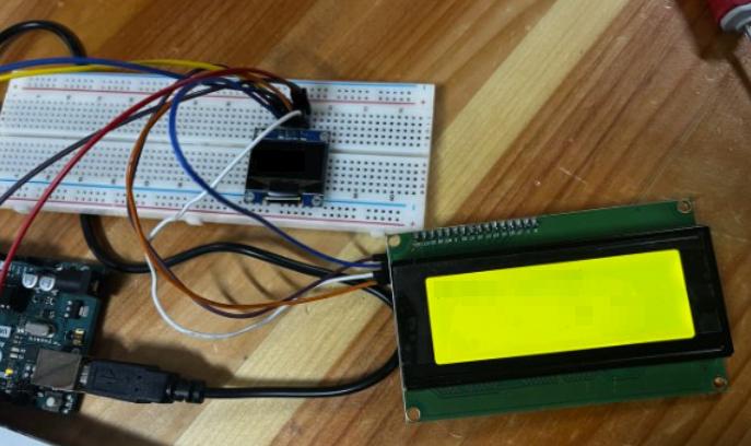
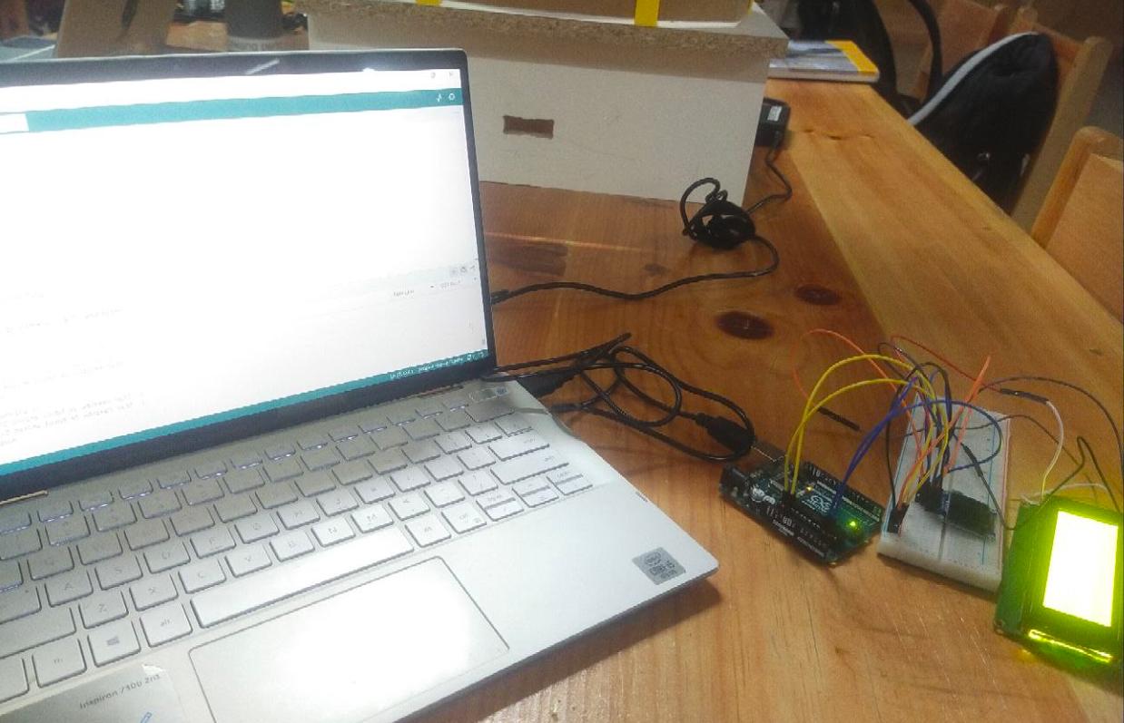
Firstly start by making connections like the above with jumper wires to the breadboard like below
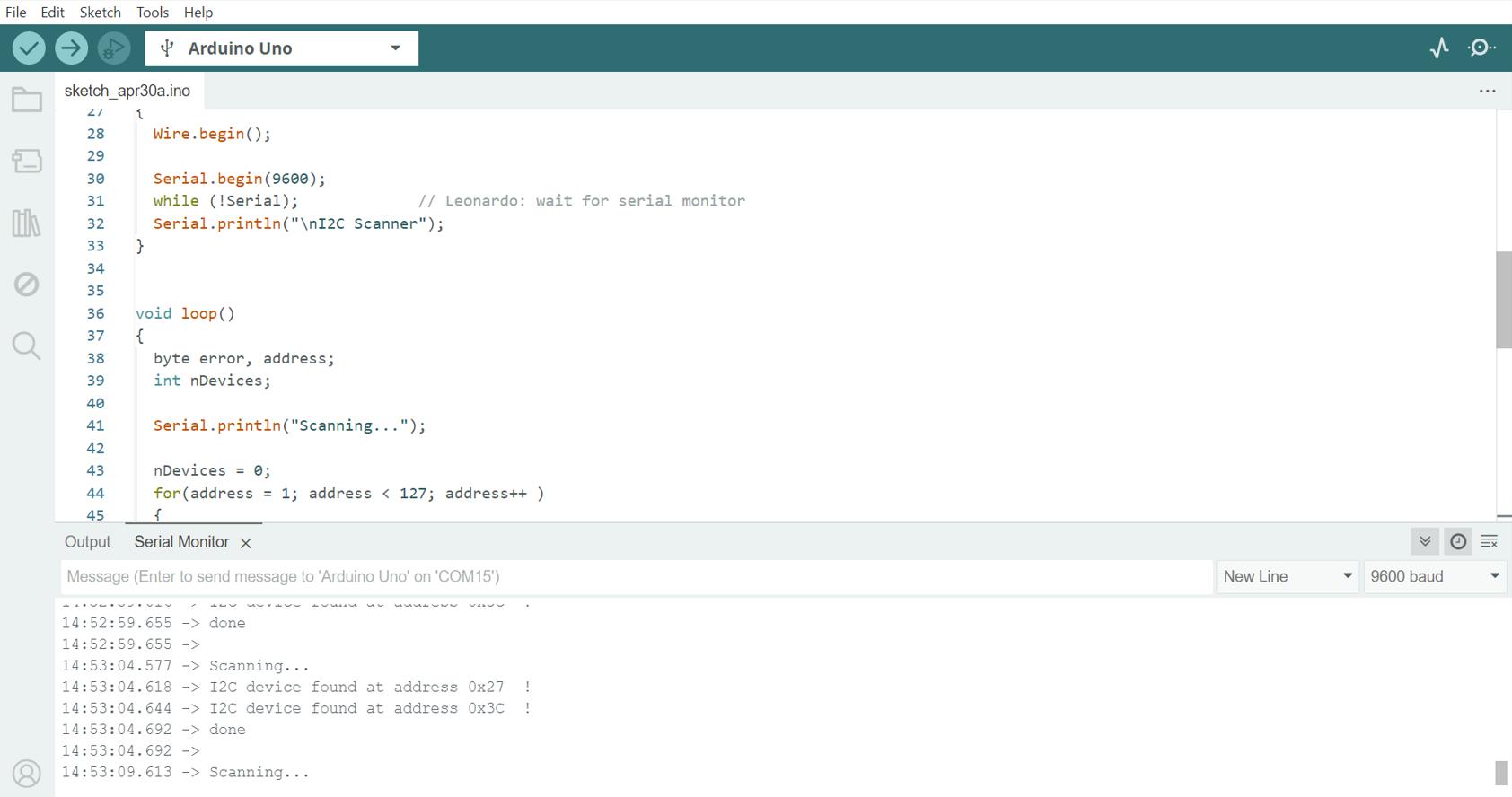
After connecting both of them to the same pins, run this code to scan the Address of each component:
I2C Scanner
This sketch tests the standard 7-bit addresses. Devices with higher bit address might not be seen properly.
After connecting both devices using the same pins, use this code to find the unique identifier of each component. I used a tutorial from Arduino's website, and the code below is what they provided.
    // The original author is not known.
    // Version 2, Juni 2012, Using Arduino 1.0.1
    //     Adapted to be as simple as possible by Arduino.cc user Krodal
    // Version 3, Feb 26  2013
    //    V3 by louarnold
    // Version 4, March 3, 2013, Using Arduino 1.0.3
    //    by Arduino.cc user Krodal.
    //    Changes by louarnold removed.
    //    Scanning addresses changed from 0...127 to 1...119,
    //    according to the i2c scanner by Nick Gammon
    //    https://www.gammon.com.au/forum/?id=10896
    // Version 5, March 28, 2013
    //    As version 4, but address scans now to 127.
    //    A sensor seems to use address 120.
    // Version 6, November 27, 2015.
    //    Added waiting for the Leonardo serial communication.
    //
    //
    // This sketch tests the standard 7-bit addresses
    // Devices with higher bit address might not be seen properly.
    //

    #include <Wire.h>

    void setup()
    {
      Wire.begin();

      Serial.begin(9600);
      while (!Serial);             // Leonardo: wait for serial monitor
      Serial.println("\nI2C Scanner");
    }

    void loop()
    {
      byte error, address;
      int nDevices;

      Serial.println("Scanning...");

      nDevices = 0;
      for(address = 1; address < 127; address++ )
      {
        // The i2c_scanner uses the return value of
        // the Write.endTransmisstion to see if
        // a device did acknowledge to the address.
        Wire.beginTransmission(address);
        error = Wire.endTransmission();

        if (error == 0)
        {
          Serial.print("I2C device found at address 0x");
          if (address<16)
            Serial.print("0");
          Serial.print(address,HEX);
          Serial.println("  !");

          nDevices++;
        }
        else if (error==4)
        {
          Serial.print("Unknown error at address 0x");
          if (address<16)
            Serial.print("0");
          Serial.println(address,HEX);
        }
      }
      if (nDevices == 0)
        Serial.println("No I2C devices found\n");
      else
        Serial.println("done\n");

      delay(5000);           // wait 5 seconds for next scan
    }
After running the code, open your serial monitor and this should show up:
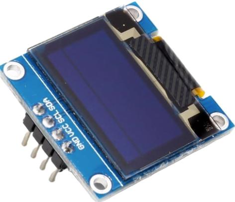
After figuring out where your OLED and LCD screens are connected, you can write a program for your Arduino to show messages on both screens at the same time. Just write some code to show one message on the OLED, then switch to the LCD to display another message. Add a pause between each message to make it look neat and coordinated. That way, you'll have both displays working together, showing whatever you want them to say.
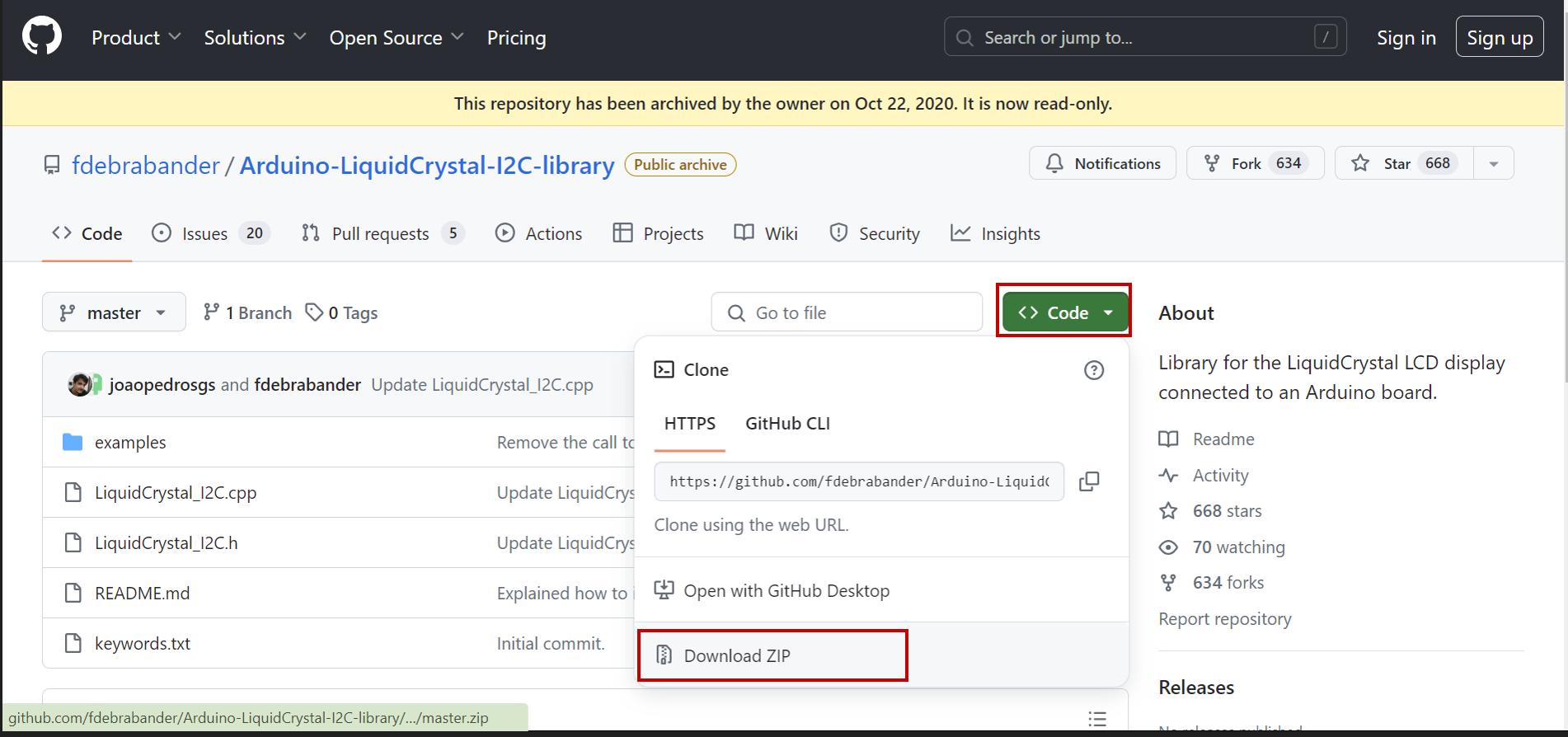
Since we will be programming a LCD I2C and an OLED , we will be needing the required libraries
To downloald the required LCD 12C library, please vist the Github link and download the .zip file.
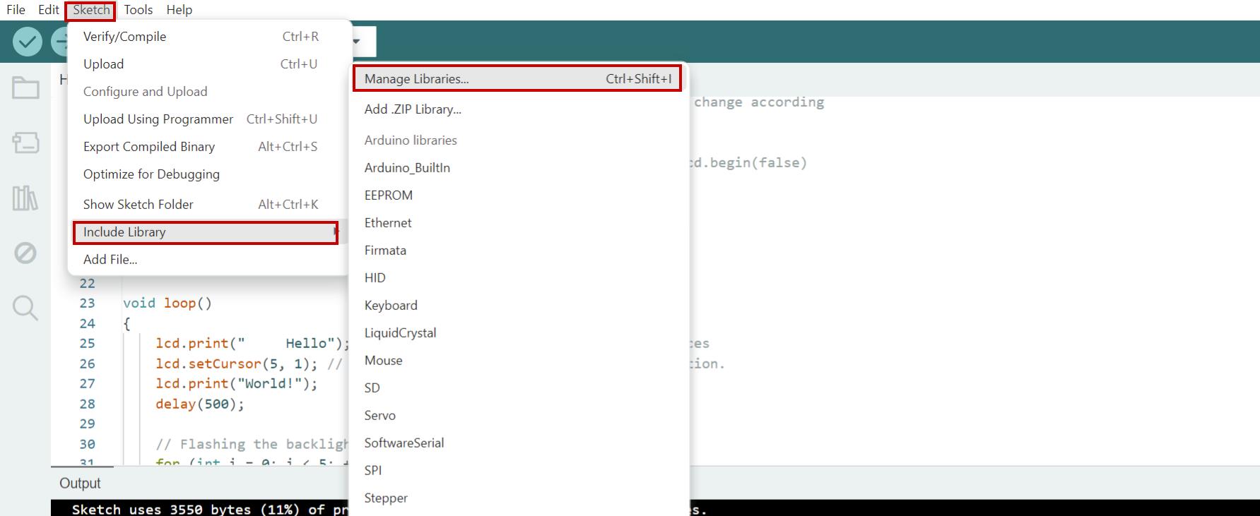
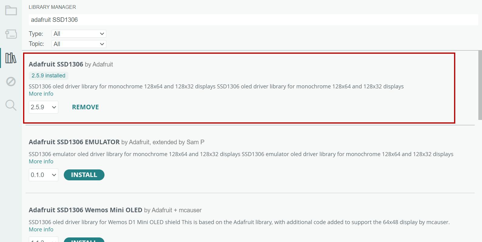
For the Adafruit_GFX.h and the Adafruit_SSD1306.h, go to sketches -> include Libraries -> Manage libraries -> Then search adafruit SSD1306.
Then upload the code below
I successfully merged the 'Hello World' example code from the LCD display and the 'Feathering' example code from the OLED display, with assistance from ChatGPT.
Below is the code that is chatgpt generated and the prompt I used is as follows:
        #include <Wire.h>
        #include <Adafruit_GFX.h>
        #include <Adafruit_SSD1306.h>
        #include <LiquidCrystal_I2C.h>

        #define OLED_ADDR 0x3C
        #define LCD_ADDR 0x27

        // Define OLED display
        Adafruit_SSD1306 display(OLED_ADDR);

        // Define LCD display
        LiquidCrystal_I2C lcd(LCD_ADDR, 20, 4); // Adjust based on your LCD size

        void setup() {
          Wire.begin();
          display.begin(SSD1306_SWITCHCAPVCC, OLED_ADDR);

          lcd.begin(); // Initialize LCD

          // Initialize displays
          display.clearDisplay();
          display.setTextSize(1);
          display.setTextColor(SSD1306_WHITE);
          display.setCursor(0,0);
          display.println("Hello OLED!");
          display.display();

          lcd.clear();
          lcd.setCursor(0, 0);
          lcd.print("Hello LCD!");
        }

        void loop() {
          // Display "Working" on both displays
          display.clearDisplay();
          display.setCursor(0,0);
          display.println("Hey Ashim?");
          display.display();

          lcd.clear();
          lcd.setCursor(0, 0);
          lcd.print("");

          delay(2000); // Delay for 2 seconds

          // Display "Testing OLED" on OLED display
          display.clearDisplay();
          display.setCursor(0,0);
          display.println("Testing OLED");
          display.display();

          // Clear LCD display
          lcd.clear();

          delay(2000); // Delay for 2 seconds

          // Display "Testing LCD" on LCD display
          lcd.setCursor(0, 0);
          lcd.print("Testing LCD");

          delay(2000); // Delay for 2 seconds

          // Display "Dawa" on OLED display
          display.clearDisplay();
          display.setCursor(0,0);
          display.println("Dawa");
          display.display();

          // Display "Seldon" on LCD display
          lcd.clear();
          lcd.setCursor(0, 0);
          lcd.print("Seldon");

          delay(2000); // Delay for 2 seconds

          // Display "is done" on OLED display
          display.clearDisplay();
          display.setCursor(0,0);
          display.println("is done with");
          display.display();

          delay(2000); // Delay for 2 seconds

          // Display "Networks and Communications Week!" on LCD display
          lcd.clear();
          lcd.setCursor(0, 0);
          lcd.print("Networks and ");
          lcd.setCursor(0, 1);
          lcd.print("Communications Week!");

          delay(2000); // Delay for 2 seconds
        }
Explaination of the Code
This example demonstrates using both an OLED and an LCD display with an Arduino.
Setup:
// Include necessary libraries and define addresses
#include <Wire.h>
#include <Adafruit_GFX.h>
#include <Adafruit_SSD1306.h>
#include <LiquidCrystal_I2C.h>
#define OLED_ADDR 0x3C
#define LCD_ADDR 0x27
// Define OLED and LCD objects
Adafruit_SSD1306 display(OLED_ADDR);
LiquidCrystal_I2C lcd(LCD_ADDR, 20, 4);
void setup() {
Wire.begin();
display.begin(SSD1306_SWITCHCAPVCC, OLED_ADDR);
lcd.begin();
// Initialize displays with text
display.clearDisplay();
display.setTextSize(1);
display.setTextColor(SSD1306_WHITE);
display.setCursor(0, 0);
display.println("Hello OLED!");
display.display();
lcd.clear();
lcd.setCursor(0, 0);
lcd.print("Hello LCD!");
}
Loop:
void loop() {
// Display "Working" on both displays
display.clearDisplay();
display.setCursor(0,0);
display.println("Hey Ashim?");
display.display();
lcd.clear();
lcd.setCursor(0, 0);
lcd.print("");
delay(2000); // Delay for 2 seconds
// Display "Testing OLED" on OLED display
display.clearDisplay();
display.setCursor(0,0);
display.println("Testing OLED");
display.display();
// Clear LCD display
lcd.clear();
delay(2000); // Delay for 2 seconds
// Display "Testing LCD" on LCD display
lcd.setCursor(0, 0);
lcd.print("Testing LCD");
delay(2000); // Delay for 2 seconds
// Display "Dawa" on OLED display
display.clearDisplay();
display.setCursor(0,0);
display.println("Dawa");
display.display();
// Display "Seldon" on LCD display
lcd.clear();
lcd.setCursor(0, 0);
lcd.print("Seldon");
delay(2000); // Delay for 2 seconds
// Display "is done" on OLED display
display.clearDisplay();
display.setCursor(0,0);
display.println("is done with");
display.display();
delay(2000); // Delay for 2 seconds
// Display "Networks and Communications Week!" on LCD display
lcd.clear();
lcd.setCursor(0, 0);
lcd.print("Networks and ");
lcd.setCursor(0, 1);
lcd.print("Communications Week!");
delay(2000); // Delay for 2 seconds
}
I was successfully able to program both the OLED and LCDI2C in the same pin to test wired connection.
Reflection
This week, I learned about how devices talk to each other. Inter-System Protocol and Intra-System Protocol are rules that help systems inside and between devices communicate smoothly. Communication Protocol sets the standards for this communication, making sure devices understand each other.
Nodes are like points in a network, each with its own address. Networks are groups of these nodes linked together. I experimented with Wired Communication, where I successfully made an OLED and LCD work together using I2C on the same pin. It showed me how devices can share resources efficiently.
I also explored Wireless Communication using the HC-05 Bluetooth Module, which offers flexibility but needs careful setup for range and interference. Bus Addressing helped me organize how devices talk without confusion.
One of my achievements was sending messages between two projects using TCP principles, ensuring data gets where it needs to reliably.
Overall, this week taught me essential skills in making devices communicate effectively, preparing me for future projects.
For this assignment, I used the board I redesigned during week 9 and was initially designed in week 8