Assignment

  • Group Assignment: measure the power consumption of an output device
  • Document your work on the group work page and reflect what you learned on your individual page
  • Individual Assignment: add an output device to a microcontroller board you've designed, and program it to do something
  • All the important links are Here

    Learning outcomes

  • Demonstrate workflows used in controlling an output device(s) with MCU board you have designed.
  • Group Assignment

    For further information, please check our Group Assignment

  • measure the power consumption of an output device
  • Measuring power consumption is a crucial aspect of assessing the energy efficiency and performance of electrical or electronic devices. Power consumption refers to the rate at which energy is used by a device and is typically measured in watts (W) or milliwatts (mW).

    To measure power consumption, you need a power meter or wattmeter, which is a device that can measure electrical power. The basic idea is to measure the current (in amperes, A) flowing through a device and the voltage (in volts, V) across it. With these measurements, you can calculate power using the formula:
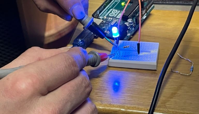
    Power (P) = Voltage (V) × Current (I)

    For our group assignment this week, we measured the power consumption of a LED.

    Note: We must always measure in series, that is, the circuit will be closed through the multimeter, so we must connect it correctly and always on a high scale or where we have the protection fuse (normally 10A).

    Equipment Needed:

    • Multimeter with an Ammeter function
    • Power source (such as a battery or power supply)
    • LED setup (LEDs, resistors, and connecting wires)

    Steps to Measure Power Consumption:

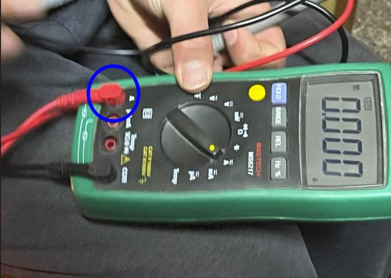
    1. Turn the multimeter dial to the Ammeter mode.
    2. Your Image Description
    3. Check the current from the power source without the LED or resistors connected.
    4. Your Image Description
    5. Connect the LED setup as follows:
      • Connect the positive terminal of the power source to the anode (+) of the LED.
      • Connect the cathode (-) of the LED to the positive (red) probe of the multimeter.
      • Connect the negative (black) probe of the multimeter to the negative terminal of the power source, completing the circuit through the multimeter.
      • Your Image Description
    6. Turn on the power source and allow the LED to illuminate fully.
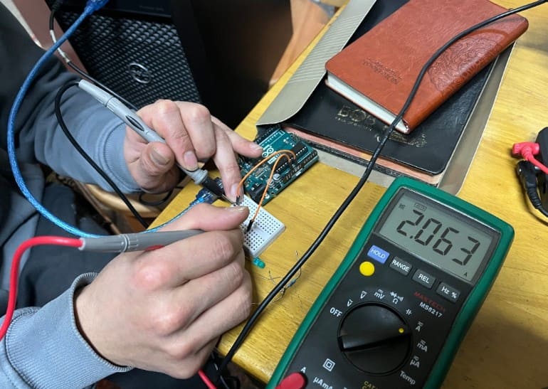
    7. Observe and record the current reading on the multimeter. This reading represents the operating current of the LED.
    8. Calculate Power Consumption:
      P = V * I
      Where:
      • P is power consumption in watts (W) or milliwatts (mW).
      • V is the voltage across the LED setup.
      • I is the current measured in amperes (A).

    Example Calculation:

    If the voltage across the LED is 3V and the measured current is 10mA (0.01A), then:

    P = 3V * 0.01A = 0.03W or 30mW

    Optional: Repeat and Average

    For more accurate results, you can repeat the measurement process multiple times and calculate the average current and power consumption.

    Individual Assignment

  • add an output device to a microcontroller board you've designed, and program it to do something
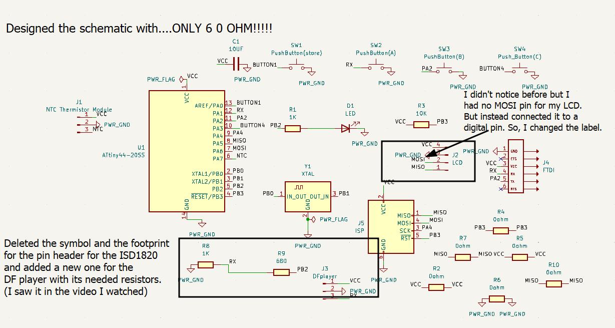
  • Firstly I satrted the week with redesigning my week 8 Electronics design week's board with lesser 0ohms.One because, it had too many 0 ohms and I didnt like it and secondly because it is no longer functionable after falling off a display shelf.And I successfully did with just 6 0 ohms this time!

    Your Image Description

    But happily a board with lesser ohms:)

    Image 1
    Image 2

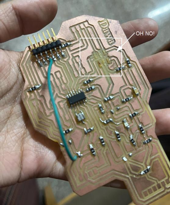
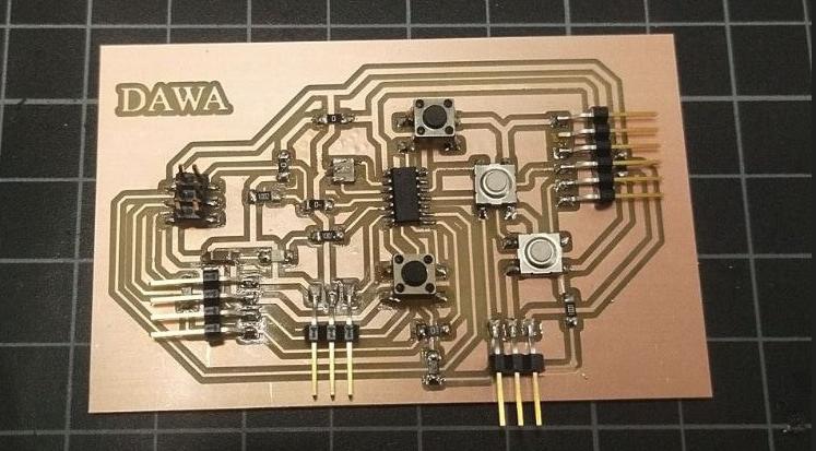
    I fabricated it and finished soldering!

    Your Image Description

    I tested the board to see if it was still working, I uploaded the button code

    But for some weird reason, without even touching the buttons the led was lighting up when it sensed you were near.

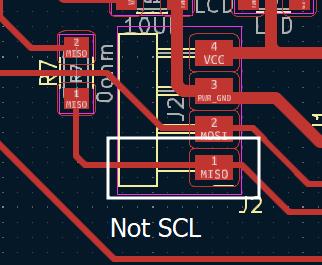
    but unfortunately when I was connecting the LCD to my board, I noticed I had no SCL pin my connector. And also when I was testing all the buttons, one of the buttons didn't work. So, I had to redesign it again.

    No worries, I will get better each time!

    Image 1
    Image 2

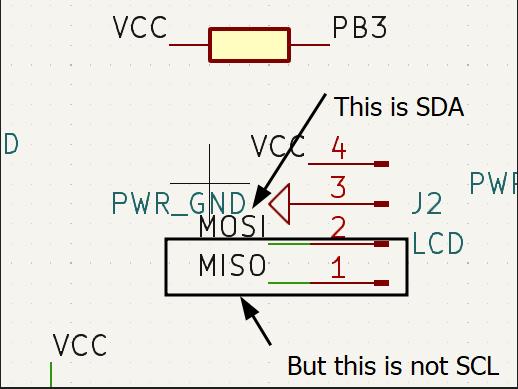
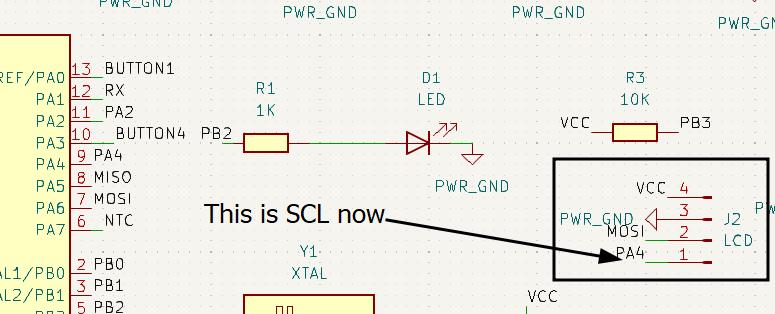
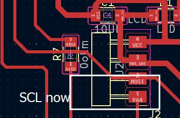
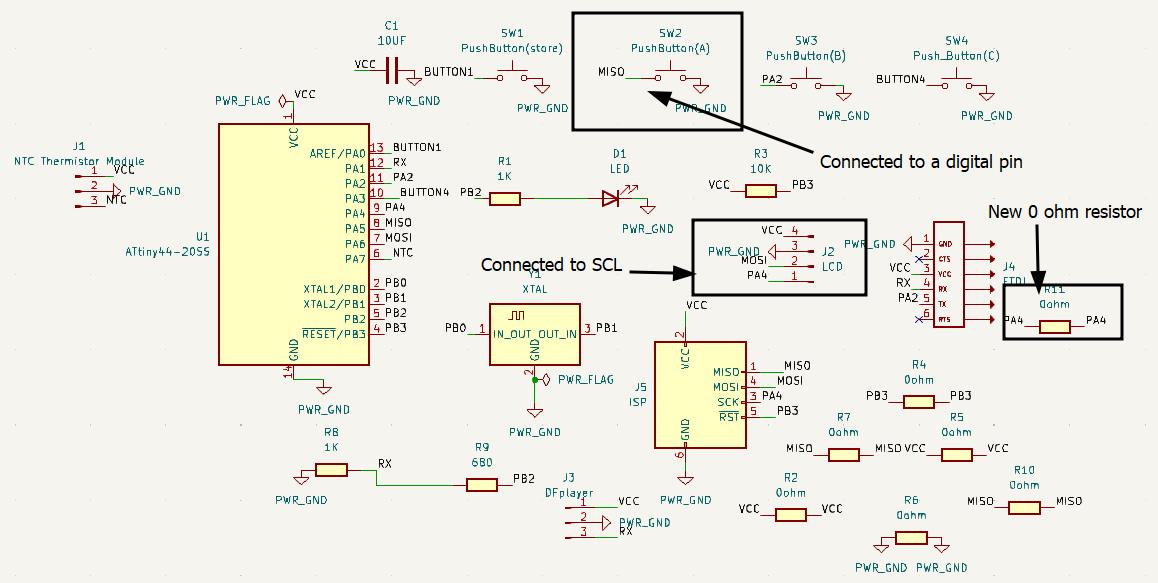
    I checked the ATtiny44 pinout again, and I found out that pin PA4 is SCL, so I changed it.

    Image 1
    Image 2

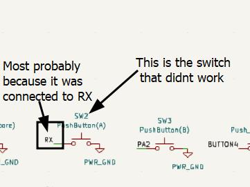
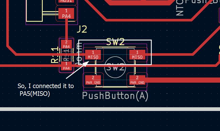
    Since one of the switch was not working I changed it too. I connected the button in RX which was not recommended.The RX pin is designed for receiving serial data, not for reading button presses. It's optimized for this specific task and may not work reliably for other purposes like digital input from a button. Using it for such tasks can lead to unpredictable behavior and isn't recommended. It's better to use other available pins specifically designed for digital input tasks like reading button presses.

    Image 1
    Image 2

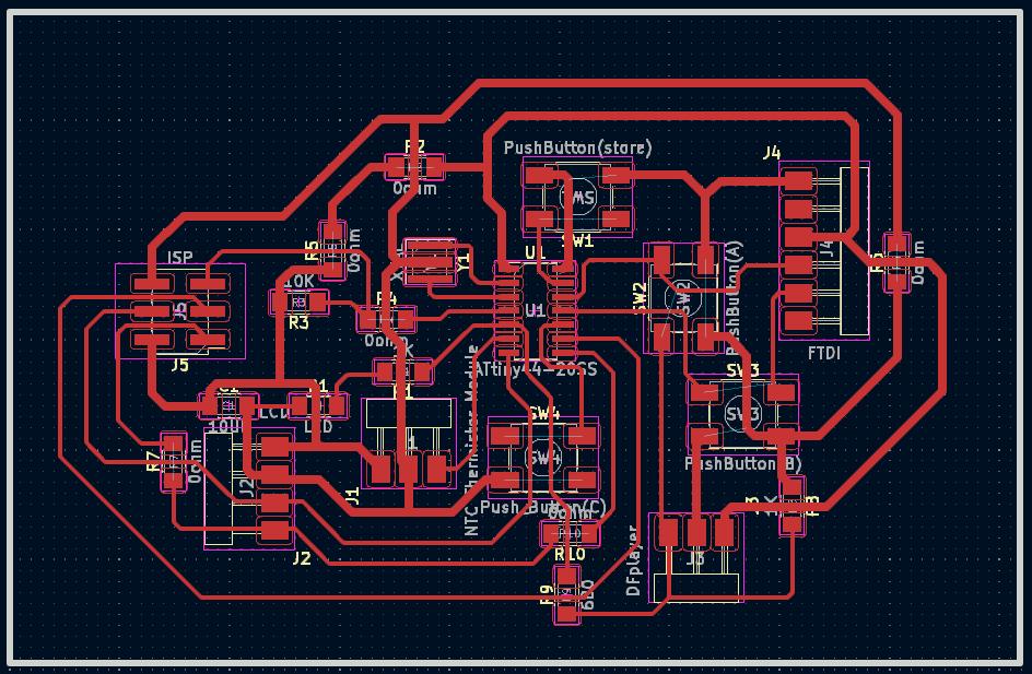
    Now, the overall schematic and PCB design with the recent changes made

    Image 1
    Image 2

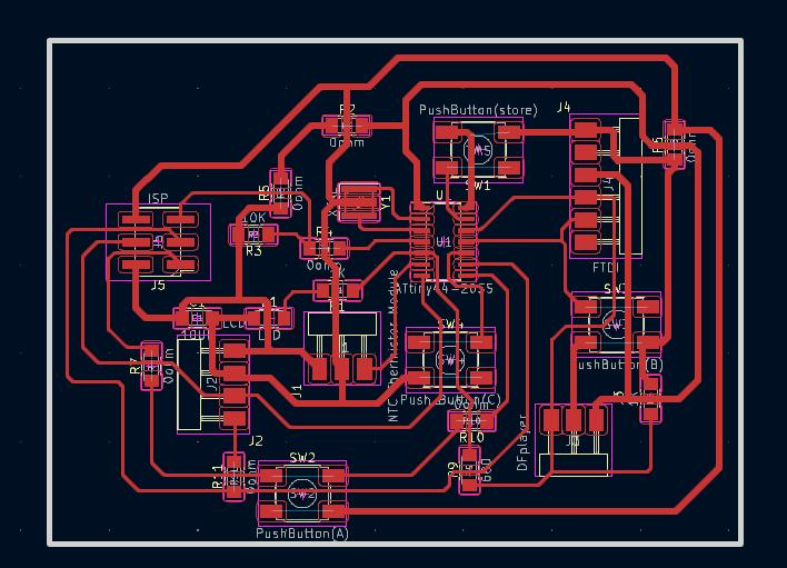
    Printed the new board

    Your Image Description

    Comparing the boards I printed this week

    Your Image Description

    Now the main assignment

    Programming a output device

    Before starting the assignment, I decided to ask chatgpt to give me definitions on what voltage and curret are. And also the definitions of the components I use so that I could understand better.

    Thank you Chatgpt for helping me understand and giving me simple definitions.

    Voltage and Current

    Voltage: Voltage is the electrical force or potential difference that pushes electric charges (electrons) through a circuit. It's measured in volts (V). Think of it like the "push" or pressure in a water pipe that makes water flow. Higher voltage means more force pushing the electrons.

    Current: Current is the rate of flow of electric charge (electrons) through a conductor in a circuit. It's measured in amperes (A), often called amps. Current tells us how many electrons are flowing past a point in the circuit per second. You can compare it to the amount of water flowing through a pipe per second.

    In summary, voltage is the electrical pressure that pushes electrons, while current is the actual flow of electrons through a conductor. Together, they determine how electricity behaves in a circuit.

    LCD I2C display

    What is a LCD?

    An LCD (Liquid Crystal Display) is a flat panel display that uses liquid crystals to create images or text.An LCD display used in projects, such as those with Arduino or Raspberry Pi, typically refers to a small screen module that integrates liquid crystal technology for displaying text, numbers, or graphics. These displays come in various sizes and can be controlled via microcontroller platforms using specific libraries and protocols like I2C or SPI.

    Thank you Chatgpt for helping me understand and giving me simple definitions.

    Your Image Description

    What is a I2C module?

    An I2C module is like a translator that helps electronic parts talk to each other using a special language called I2C. It's like a connector that allows different devices to communicate smoothly and share information.

    Thank you Chatgpt for helping me understand and giving me simple definitions.

    Your Image Description

    LCD I2C
    Your Image Description

    To work with the LCD I2C, I needed to get an additional library because the standard Arduino IDE library doesn't support LCDs with I2C modules. It's like getting an extra tool to make sure the LCD and the I2C module can understand each other and work together properly.

    For the additional library, you can download it from here Downloading the additional library Download the .zip file that the link above leads you to.
    Image 1
    Image 2
    Image 1
    Image 2
    Image 1
    Image 2

    Arduino Example code, LCD I2C

    
    /*
    *	Hello_World.ino
    *
    *	Author: Frank Häfele
    *	Date:	01.12.2023
    *
    *	Object: Print Hello World on LCD Display
    */
    
    #include 
    
    
    LCD_I2C lcd(0x27, 16, 2); // Default address of most PCF8574 modules, change according
    
    void setup() {
        // If you are using more I2C devices using the Wire library use lcd.begin(false)
        // this stop the library(LCD-I2C) from calling Wire.begin()
        lcd.begin();
        lcd.display();
        lcd.backlight();
    }
    
    void loop()
    {
        lcd.print("     Hello"); // You can make spaces using well... spaces
        lcd.setCursor(5, 1); // Or setting the cursor in the desired position.
        lcd.print("World!");
        delay(500);
    
        // Flashing the backlight
        for (int i = 0; i < 5; ++i)
        {
            lcd.backlight();
            delay(50);
            lcd.backlightOff();
            delay(50);
        }
    
        lcd.backlight();
        lcd.clear();
        delay(500);
    }


    Since I am a beginner in using the LCD I2C I didnt understand the whole code. So I asked Chatgpt to explain it to me.

    Explanation of Arduino Code: Hello World on LCD I2C

    Here’s a breakdown of the Arduino code I used to display "Hello World!" on an LCD screen:

    Setup

    The code included the necessary library to communicate with the LCD using #include <LCD-I2C.h>.

    The line LCD_I2C lcd(0x27, 16, 2); initializes the LCD object with the address and size of the display.

    In the setup() function:

    • lcd.begin(); initializes the LCD.
    • lcd.display(); turns on the LCD display.
    • lcd.backlight(); lights up the LCD backlight.

    Loop

    The loop() function runs continuously:

    • lcd.print(" Hello"); prints "Hello" with leading spaces for formatting.
    • lcd.setCursor(5, 1); sets the cursor at column 5, row 1.
    • lcd.print("World!"); prints "World!" starting from the set cursor position.
    • delay(500); pauses execution for half a second.
    • A loop flashes the backlight five times for visual effect.
    • lcd.clear(); clears the LCD screen.
    • delay(500); pauses execution for another half second before repeating.
    
            lcd.print("     Hello");
            lcd.setCursor(5, 1);
            lcd.print("World!");
            delay(500);
                

    lcd.print(" Hello"); prints "Hello" with leading spaces for formatting. This line demonstrates how to use spaces to align text on the LCD display.

    lcd.setCursor(5, 1); sets the cursor at column 5, row 1 on the LCD display. This function allows you to position where the next text or character will be printed.

    lcd.print("World!"); prints "World!" starting from the cursor position set by lcd.setCursor(5, 1);. This shows how to print text at a specific location on the LCD screen.

    delay(500); pauses execution for half a second. It adds a delay before the LCD screen is cleared and the loop repeats.

    Conclusion

    This code continuously displays "Hello World!" on the LCD, with a flashing backlight effect every half-second. It's a basic example of using an Arduino with an LCD screen.

    It worked!

    Next, I just changed the text

    Files

    Board