Networking and Communications
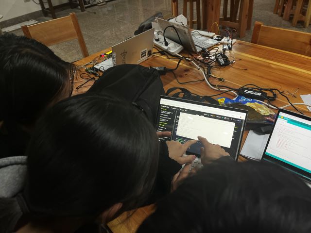
Group assignment:
- Send a message between two projects
- Document your work to the group work page and reflect on your individual page what you learned
Individual assignment:
- Design, build and connect wired or wireless node(s) with network or bus addresses and a local interface
Learning outcomes
- Demonstrate workflows used in network design
- Implement and interpret networking protocols and/or communication protocols
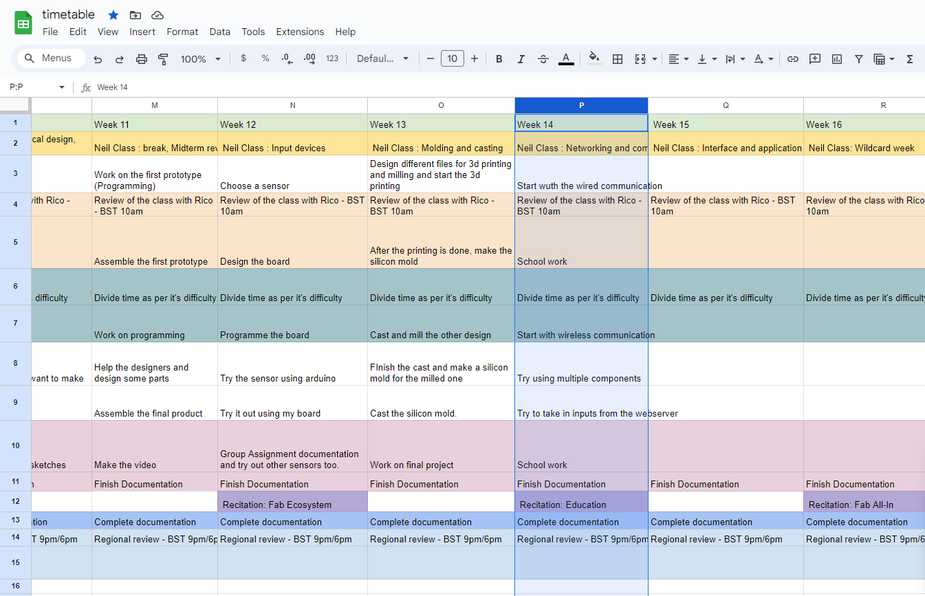
As usual here is my timetable:
Group Assignment
Conclusion:
And with that, we are finally done with this weeks group assignment. I must say, we learned a lot with this weeks assignment we did. Planning, integration and then finally testing of our codes. How if planned properly, each and everything can go smoothly and as you want. But it is also important to consider how crucial making mistakes are. But yeah, for this week this is it.
Click here to view the group assignment.
Individual Assignment
Protocol for Communication.
Communication protocols are defined as the correct definitions of digital message formats and standards. These protocols’ primary purpose is to transfer messages between different computer systems. They are important because they reliably send and receive messages in telecommunications networks. These protocols deal with authentication, signaling, and error detection and repair.
What is the purpose of using several processors?·
- Location: Manage various parts in other places
- Parallelism: Several threads can run concurrently on a desktop computer. The job is distributed across the processors. system of processors as opposed to a single large one.
- Modularity: Divide a large system into numerous smaller ones. For example, one person can operate the motor alone, handle the display alone, or converse with the container alone. aids in the system’s development and debugging process individually before coming together.
- Interference: This is ideal for it because it can require a high current drive for a motor and a low noise sensor.
Wired communication
Communication systems rely on mediums through which devices exchange data. Wired communication utilizes physical cables for data transmission, with additional equipment like switches or repeaters used to enhance signal flow over varying distances. This method is highly reliable due to minimal environmental interference.

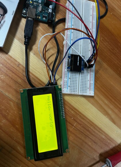
For the wired communication, I decided to control an oled and a 20x4 i2c lcd through the same pins; SDA and SCL which will follow the Inter-Integrated Circuit protocol.
I2C (Inter-Integrated Circuit)
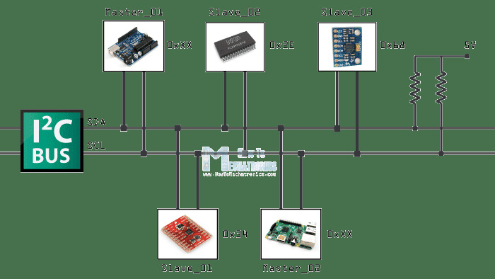
I2C (Inter-Integrated Circuit) is a communication protocol used in electronics to enable data exchange between integrated circuits (ICs) or microcontrollers. It utilizes two wires for communication: SDA (Serial Data Line) and SCL (Serial Clock Line). The SCL line carries a clock signal that synchronizes data transfer, while the SDA line carries the actual data. Each device on the bus has a unique address, allowing multiple devices to communicate with each other without conflicts. I2C facilitates serial communication with relatively low hardware overhead, making it suitable for applications where multiple devices need to communicate over short distances, such as in sensors, displays, and memory modules.
SO firstly, I will be using an arduino board to test the wired communication and then try it out using my own board which I printed during Electronics Design week (AKA week 8). Now let’s begin!!
Firstly, start off by connecting the oled and the lcd to the arduino like this:
After connecting both of them to the same pins, run this code to scan the Address of each component. I followed the tutorial from this Arduino link and the code below is also from the link.
//    The original author is not know.
// Version 2, Juni 2012, Using Arduino 1.0.1
//     Adapted to be as simple as possible by Arduino.cc user Krodal
// Version 3, Feb 26  2013
//    V3 by louarnold
// Version 4, March 3, 2013, Using Arduino 1.0.3
//    by Arduino.cc user Krodal.
//    Changes by louarnold removed.
//    Scanning addresses changed from 0...127 to 1...119,
//    according to the i2c scanner by Nick Gammon
//    https://www.gammon.com.au/forum/?id=10896
// Version 5, March 28, 2013
//    As version 4, but address scans now to 127.
//    A sensor seems to use address 120.
// Version 6, November 27, 2015.
//    Added waiting for the Leonardo serial communication.
//
//
// This sketch tests the standard 7-bit addresses
// Devices with higher bit address might not be seen properly.
//

#include <Wire.h>


void setup()
{
  Wire.begin();

  Serial.begin(9600);
  while (!Serial);             // Leonardo: wait for serial monitor
  Serial.println("\nI2C Scanner");
}


void loop()
{
  byte error, address;
  int nDevices;

  Serial.println("Scanning...");

  nDevices = 0;
  for(address = 1; address < 127; address++ )
  {
    // The i2c_scanner uses the return value of
    // the Write.endTransmisstion to see if
    // a device did acknowledge to the address.
    Wire.beginTransmission(address);
    error = Wire.endTransmission();

    if (error == 0)
    {
      Serial.print("I2C device found at address 0x");
      if (address<16)
        Serial.print("0");
      Serial.print(address,HEX);
      Serial.println("  !");

      nDevices++;
    }
    else if (error==4)
    {
      Serial.print("Unknown error at address 0x");
      if (address<16)
        Serial.print("0");
      Serial.println(address,HEX);
    }
  }
  if (nDevices == 0)
    Serial.println("No I2C devices found\n");
  else
    Serial.println("done\n");

  delay(5000);           // wait 5 seconds for next scan
}
After running the code, open your serial monitor and this should show up:

After getting the address for each component, you can now code as per your likings. SO I will be programming on making both my oled and lcd display messages at the same time with some delay in between.
Since we are using 12c lcd and an oled, we have to download these libraries:
LiquidCrystal_I2C.h
Adafruit_GFX.h
Adafruit_SSD1306.h
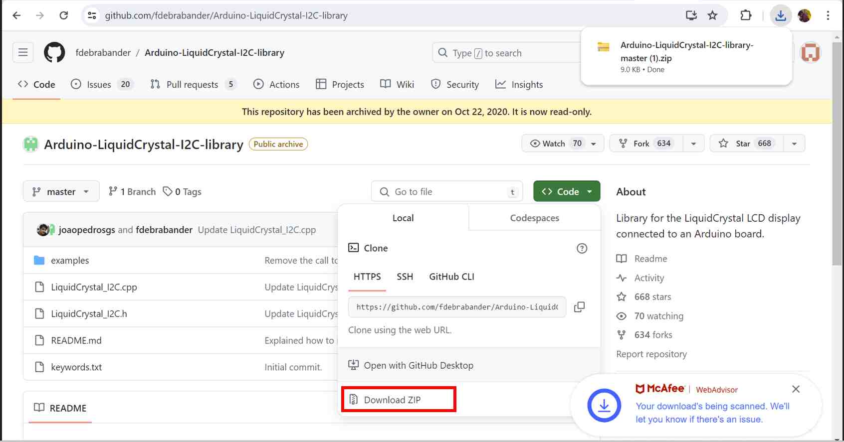
To download the LiquidCrystal_I2C.h library, go to this github link and download the zip file like this:
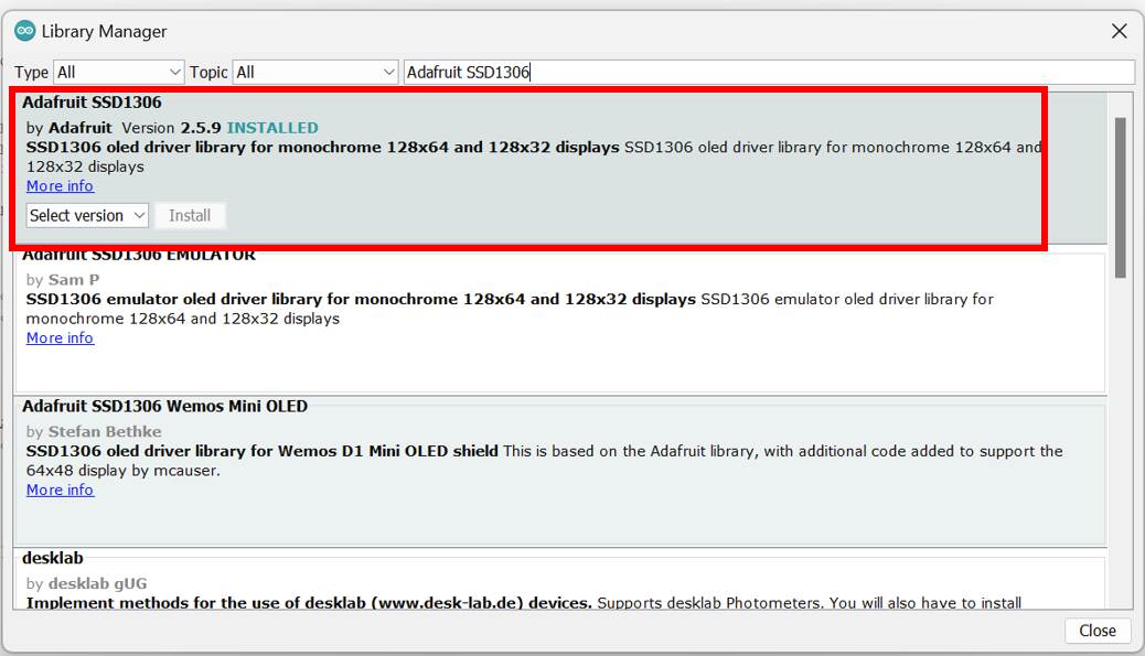
For the Adafruit_GFX.h and the Adafruit_SSD1306.h, go to sketches -> include Libraries -> Manage libraries -> Then search adafruit SSD1306 and remember to download the whole package like this:

So here is the code:
#include <Wire.h>
#include <LiquidCrystal_I2C.h>
#include <Adafruit_GFX.h>
#include <Adafruit_SSD1306.h>

// LCD settings
#define LCD_ADDRESS 0x27
#define LCD_COLS 20
#define LCD_ROWS 4
LiquidCrystal_I2C lcd(LCD_ADDRESS, LCD_COLS, LCD_ROWS);

// OLED settings
#define SCREEN_WIDTH 128 // OLED display width, in pixels
#define SCREEN_HEIGHT 64 // OLED display height, in pixels
#define OLED_RESET     -1 // Reset pin # (or -1 if sharing Arduino reset pin)
#define OLED_ADDRESS 0x3C
Adafruit_SSD1306 display(SCREEN_WIDTH, SCREEN_HEIGHT, &Wire, OLED_RESET);

void setup() {
  // Initialize the LCD
  lcd.backlight();
  lcd.setCursor(0, 0);
  lcd.print("Hello, LCD!");

  // Initialize the OLED
  if (!display.begin(SSD1306_SWITCHCAPVCC, OLED_ADDRESS)) {
    for (;;); // Don't proceed, loop forever
  }
  display.clearDisplay();
  display.setTextSize(1);             // Normal 1:1 pixel scale
  display.setTextColor(SSD1306_WHITE); // Draw white text
  display.setCursor(0, 0);
  display.println("Hello, OLED!");
  display.display();
}

void loop() {
  // Here, you can add code to update the displays or perform other tasks.
  // For demonstration, let's rotate text on both displays every 2 seconds.

  // Update LCD
  lcd.clear();
  lcd.setCursor(0, 1); // Move to the second line
  lcd.print("Refreshing...");
  delay(2000); // Wait for 2000 milliseconds

  // Update OLED
  display.clearDisplay();
  display.setCursor(0, 10); // Move down a bit
  display.println("Hi there!!");
  display.display();
  delay(2000); // Wait for 2000 milliseconds

  // Show another message
  lcd.clear();
  lcd.print("Damzang ROcks!!");
  display.clearDisplay();
  display.setCursor(0, 20);
  display.println("Fab academy!");
  display.display();
  delay(2000);
}
For this code, I combined the example codes fro Liquid cyrstal aka lcd and the oled, namely the ‘Hello World’ code fro lcd and the ‘Oled Festhering’ code for the oled. With the help of ChatGPT, I was able to successfully combine the 2 codes as per my requirement!
Here is how it looks after the code is uploaded:
Now let’s try it on my Xiao esp32 c3 board. SO we have to upload the same code and since we already downloaded the libraries, we just need to change the ‘board’ and select the correct port!
Wireless communication
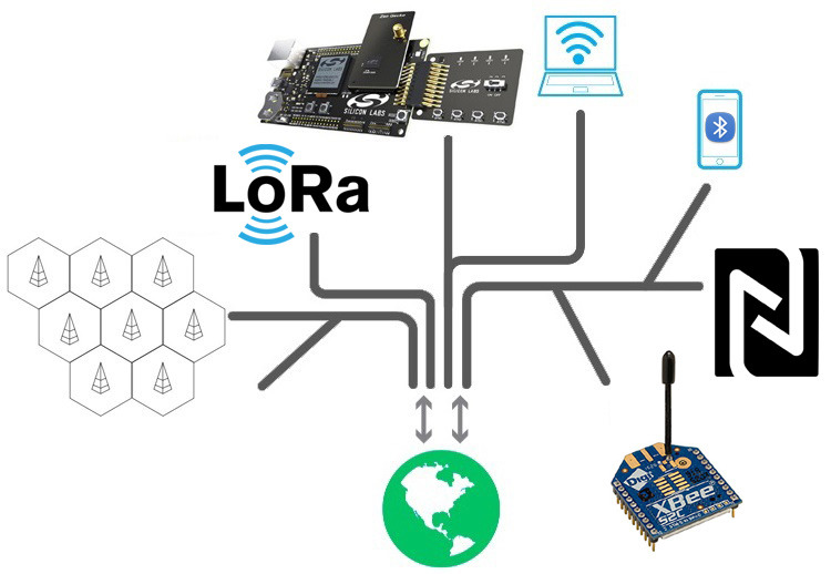
Conversely, wireless communication employs the air as the medium, with performance largely dictated by the communication protocol used. Short-range protocols like Wi-Fi and Bluetooth offer limited coverage, while long-range protocols such as LoRa, GSM, FM, and AM enable broader communication spans. The choice of protocol directly impacts communication range and efficiency.
So for the wireless communication, I will be hosting a web server through my xiao esp 32c3. SO to host wireless communication using wifi, I followed this toturialto get started. SO firstly, we have to connect WiFi/ Bluetooth antenna to the IPEX connector on the board. like this:

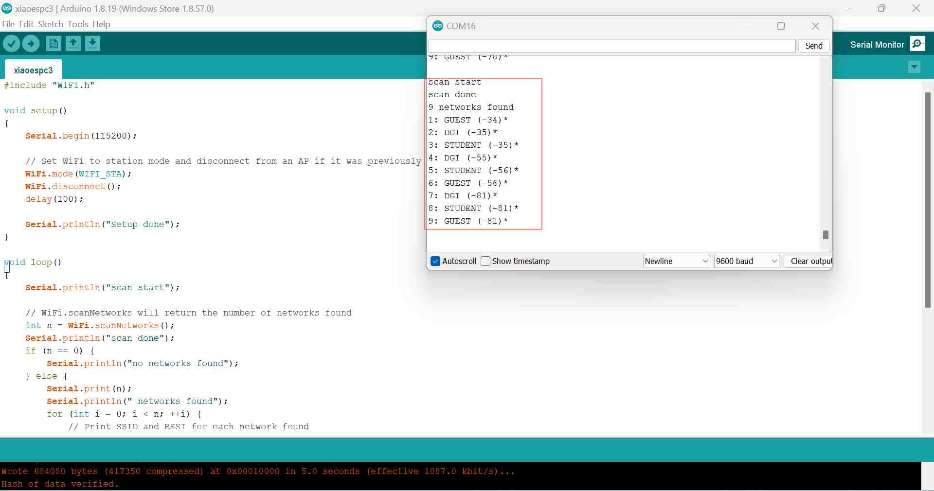
After that, run this code (which I got from the link i mentioned above) to check the available networks nearby.
#include "WiFi.h"

void setup()
{
    Serial.begin(115200);

    // Set WiFi to station mode and disconnect from an AP if it was previously connected
    WiFi.mode(WIFI_STA);
    WiFi.disconnect();
    delay(100);

    Serial.println("Setup done");
}

void loop()
{
    Serial.println("scan start");

    // WiFi.scanNetworks will return the number of networks found
    int n = WiFi.scanNetworks();
    Serial.println("scan done");
    if (n == 0) {
        Serial.println("no networks found");
    } else {
        Serial.print(n);
        Serial.println(" networks found");
        for (int i = 0; i < n; ++i) {
            // Print SSID and RSSI for each network found
            Serial.print(i + 1);
            Serial.print(": ");
            Serial.print(WiFi.SSID(i));
            Serial.print(" (");
            Serial.print(WiFi.RSSI(i));
            Serial.print(")");
            Serial.println((WiFi.encryptionType(i) == WIFI_AUTH_OPEN)?" ":"*");
            delay(10);
        }
    }
    Serial.println("");

    // Wait a bit before scanning again
    delay(5000);
}
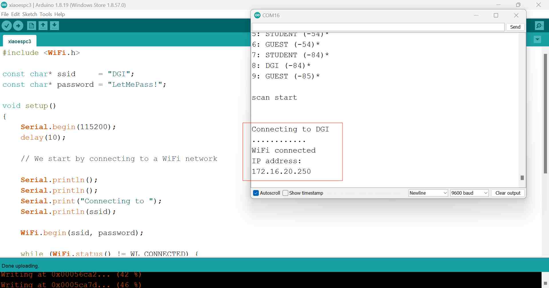
After uploading the code, this is what should show up in your serial monitor:
After that, select the network you want to work with and upload this code to get the ip address:
This code is also from the link I mentioned above!
#include <WiFi.h>

const char* ssid     = "yourssid";
const char* password = "your-password";

void setup()
{
    Serial.begin(115200);
    delay(10);

    // We start by connecting to a WiFi network

    Serial.println();
    Serial.println();
    Serial.print("Connecting to ");
    Serial.println(ssid);

    WiFi.begin(ssid, password);

    while (WiFi.status() != WL_CONNECTED) {
        delay(500);
        Serial.print(".");
    }

    Serial.println("");
    Serial.println("WiFi connected");
    Serial.println("IP address: ");
    Serial.println(WiFi.localIP());
}
void loop()
{
  }
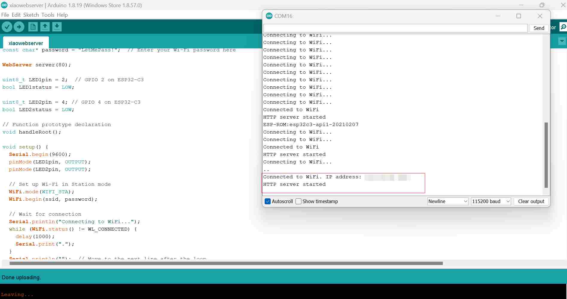
This is how your serial monitor should look like afer uploading the code:
After you have gotten your ip address you now know how to connect to your network, let’s get started by controlling leds through the webserver using this code:
#include <WiFi.h>
#include <WebServer.h>

/* Put your SSID & Password */
const char* ssid = "dummy-ssid";  // Enter your SSID here
const char* password = "your ssid password";  // Enter your Wi-Fi password here

WebServer server(80);

uint8_t LED1pin = 2;  // GPIO 2 on ESP32-C3
bool LED1status = LOW;

uint8_t LED2pin = 4; // GPIO 4 on ESP32-C3
bool LED2status = LOW;

// Function prototype declaration
void handleRoot();

void setup() {
  Serial.begin(9600);
  pinMode(LED1pin, OUTPUT);
  pinMode(LED2pin, OUTPUT);

  // Set up Wi-Fi in Station mode
  WiFi.mode(WIFI_STA);
  WiFi.begin(ssid, password);

  // Wait for connection
  Serial.println("Connecting to WiFi...");
  while (WiFi.status() != WL_CONNECTED) {
    delay(1000);
    Serial.print(".");
  }
  Serial.println("");  // Move to the next line after the loop

  // Print ESP32-C3's IP address
  Serial.print("Connected to WiFi. IP address: ");
  Serial.println(WiFi.localIP());

  // Register handlers after defining handleRoot
  server.on("/", HTTP_GET, handleRoot);
  server.on("/led1on", HTTP_GET, []() {
    LED1status = HIGH;
    server.send(200, "text/html", SendHTML(LED1status, LED2status));
  });
  server.on("/led1off", HTTP_GET, []() {
    LED1status = LOW;
    server.send(200, "text/html", SendHTML(LED1status, LED2status));
  });
  server.on("/led2on", HTTP_GET, []() {
    LED2status = HIGH;
    server.send(200, "text/html", SendHTML(LED1status, LED2status));
  });
  server.on("/led2off", HTTP_GET, []() {
    LED2status = LOW;
    server.send(200, "text/html", SendHTML(LED1status, LED2status));
  });

  server.begin();
  Serial.println("HTTP server started");
}

void loop() {
  server.handleClient();
  digitalWrite(LED1pin, LED1status);
  digitalWrite(LED2pin, LED2status);
}


String SendHTML(uint8_t led1stat, uint8_t led2stat) {
  String ptr = "<!DOCTYPE html> <html>\n";
  ptr += "<head><meta name=\"viewport\" content=\"width=device-width, initial-scale=1.0, user-scalable=no\">\n";
  ptr += "<title>LED Control</title>\n";
  ptr += "<style>html { font-family: Helvetica; display: inline-block; margin: 0px auto; text-align: center;}\n";
  ptr += "body{margin-top: 50px;} h1 {color: #444444;margin: 50px auto 30px;} h3 {color: #444444;margin-bottom: 50px;}\n";
  ptr += ".button {display: block;width: 80px;background-color: #3498db;border: none;color: white;padding: 13px 30px;text-decoration: none;font-size: 25px;margin: 0px auto 35px;cursor: pointer;border-radius: 4px;}\n";
  ptr += ".button-on {background-color: #3498db;}\n";
  ptr += ".button-on:active {background-color: #2980b9;}\n";
  ptr += ".button-off {background-color: #34495e;}\n";
  ptr += ".button-off:active {background-color: #2c3e50;}\n";
  ptr += "p {font-size: 14px;color: #888;margin-bottom: 10px;}\n";
  ptr += "</style>\n";
  ptr += "</head>\n";
  ptr += "<body>\n";
  ptr += "<h1>ESP32-C3 Web Server</h1>\n";
  ptr += "<h3>Using Station(AP) Mode</h3>\n";
  ptr += "<p>LED1 Status: ";
  if (led1stat) {
    ptr += "ON</p><a class=\"button button-off\" href=\"/led1off\">OFF</a>\n";
  } else {
    ptr += "OFF</p><a class=\"button button-on\" href=\"/led1on\">ON</a>\n";
  }
  ptr += "<p>LED2 Status: ";
  if (led2stat) {
    ptr += "ON</p><a class=\"button button-off\" href=\"/led2off\">OFF</a>\n";
  } else {
    ptr += "OFF</p><a class=\"button button-on\" href=\"/led2on\">ON</a>\n";
  }
  ptr += "</body>\n";
  ptr += "</html>\n";
  return ptr;
}

// Definition of handleRoot function
void handleRoot() {
  server.send(200, "text/html", SendHTML(LED1status, LED2status));
}
For this code, I used the blink led code and integrated it such that I can control it through the webserver. I also used simple HTML for the webserver. This was all possible due to correct prompting to AI, specifically ChatGPT.(SO I give the credits to AI!!)
SO here is a short explanation of the code:
The setup() function initializes the Arduino environment by configuring serial communication, setting pin modes for LED control, connecting to Wi-Fi, and starting the web server. It continuously checks for Wi-Fi connection until successful, then prints the ESP32-C3’s IP address. Routes for controlling each LED are defined here, linking to functions to turn them on or off. Finally, the server begins operation, and a message indicates its start.
In the loop() function, the server continually handles incoming client requests while simultaneously updating the LED states based on the variables LED1status and LED2status. This ensures that the LEDs respond to control commands from the web interface in real-time. The loop essentially maintains the server’s functionality and updates the LEDs accordingly.
SO here is how the serial monitor and the webpage looked like:
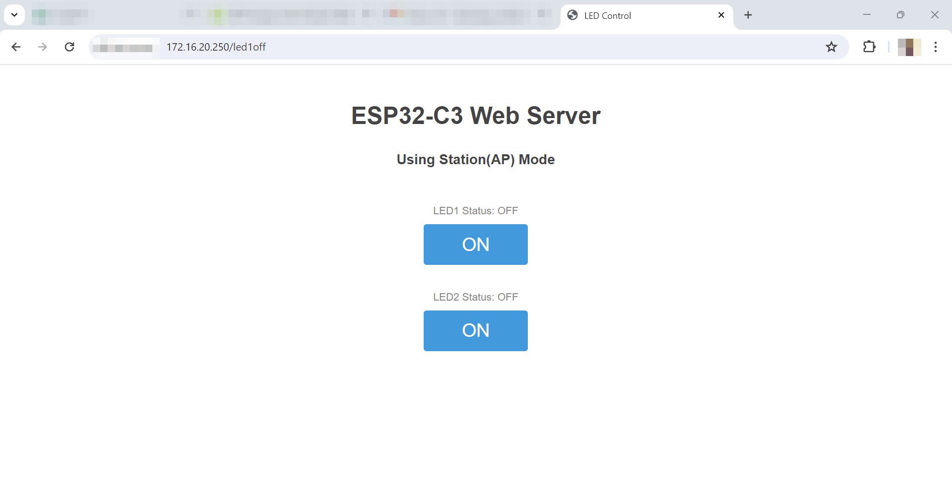
And here is a video showing how it turned out!
Since I was able to control a led, I moved on to controlling an oled and for this also I used the ‘oled feathering’ code and replaced it intead of the led code. (For this, I coded it myself and luckily it worked!):
#include <Wire.h>
#include <Adafruit_GFX.h>
#include <Adafruit_SSD1306.h>
#include <WiFi.h>
#include <WebServer.h>

/* Put your SSID & Password */
const char* ssid = "dummy-ssid";  // Enter your SSID here
const char* password = "dummy-password";  // Enter your Wi-Fi password here

WebServer server(80);

#define SCREEN_WIDTH 128 // OLED display width, in pixels
#define SCREEN_HEIGHT 64 // OLED display height, in pixels
#define OLED_RESET    -1 // Reset pin # (or -1 if sharing Arduino reset pin)
Adafruit_SSD1306 display(SCREEN_WIDTH, SCREEN_HEIGHT, &Wire, OLED_RESET);


void handleRoot();
void handleDisplayMessage();

void setup() {
  Serial.begin(115200);


  // Set up Wi-Fi in Station mode
  WiFi.mode(WIFI_STA);
  WiFi.begin(ssid, password);
  Serial.println("Connecting to WiFi...");
  while (WiFi.status() != WL_CONNECTED) {
    delay(1000);
    Serial.print(".");
  }
  Serial.println("");  // Print new line after successful connection
  Serial.print("IP Address: ");
  Serial.println(WiFi.localIP()); // Print IP address to Serial Monitor
  Serial.println("Connected to WiFi");

  // Register handlers
  server.on("/", HTTP_GET, handleRoot);
  server.on("/displaymessage", HTTP_GET, handleDisplayMessage);

  server.begin();
  Serial.println("HTTP server started");

  // Initialize OLED display
  if(!display.begin(SSD1306_SWITCHCAPVCC, 0x3C)) {
    Serial.println(F("SSD1306 allocation failed"));
    for(;;);
  }
  display.display();
  delay(2000); // Pause for 2 seconds
  display.clearDisplay();
}

void loop() {
  server.handleClient();
}

String SendHTML() {
  String ptr = "<!DOCTYPE html> <html>\n";
  ptr += "<head><meta name=\"viewport\" content=\"width=device-width, initial-scale=1.0, user-scalable=no\">\n";
  ptr += "<title>ESP32-C3 Web Server</title>\n";
  ptr += "<style>html { font-family: Helvetica; display: inline-block; margin: 0px auto; text-align: center;}\n";
  ptr += "body{margin-top: 50px;} h1 {color: #444444;margin: 50px auto 30px;} h3 {color: #444444;margin-bottom: 50px;}\n";
  ptr += "</style>\n";
  ptr += "</head>\n";
  ptr += "<body>\n";
  ptr += "<h1>ESP32-C3 Web Server</h1>\n";
  ptr += "<h3>Using Station(AP) Mode</h3>\n";
  ptr += "<p><a href=\"/displaymessage\">Display Message on OLED</a></p>\n";
  ptr += "</body>\n";
  ptr += "</html>\n";
  return ptr;
}

// Definition of handleRoot function
void handleRoot() {
  server.send(200, "text/html", SendHTML());
}

void handleDisplayMessage() {
  if (server.method() == HTTP_GET) {

    // Display message on OLED
    display.clearDisplay();
    display.setTextSize(1);
    display.setTextColor(SSD1306_WHITE);
    display.setCursor(0,0);
    display.println("Message from Web Server!");
    display.display();
    delay(5000); // Display the message for 5 seconds
    display.clearDisplay();

    // Send response to client
    server.send(200, "text/html", SendHTML());
  }
}
Here is a video of the oled display:
Now let’s raise our bar a bit and control an oled and the leds together. SO i ran the code below which I basically just added the led code again and made it such that the message and the led would be displayed/ blink at the same time:
#include <Wire.h>
#include <Adafruit_GFX.h>
#include <Adafruit_SSD1306.h>
#include <WiFi.h>
#include <WebServer.h>

/* Put your SSID & Password */
const char* ssid = "dummy-ssid";  // Enter your SSID here
const char* password = "dummy-password";  // Enter your Wi-Fi password here

WebServer server(80);

#define SCREEN_WIDTH 128 // OLED display width, in pixels
#define SCREEN_HEIGHT 64 // OLED display height, in pixels
#define OLED_RESET    -1 // Reset pin # (or -1 if sharing Arduino reset pin)
Adafruit_SSD1306 display(SCREEN_WIDTH, SCREEN_HEIGHT, &Wire, OLED_RESET);

// LED pins
const uint8_t LED1pin = 2;  // GPIO 2 on ESP32-C3
const uint8_t LED2pin = 4;  // GPIO 4 on ESP32-C3

void handleRoot();
void handleDisplayMessage();

void setup() {
  Serial.begin(115200);

  pinMode(LED1pin, OUTPUT);
  pinMode(LED2pin, OUTPUT);

  // Set up Wi-Fi in Station mode
  WiFi.mode(WIFI_STA);
  WiFi.begin(ssid, password);
  Serial.println("Connecting to WiFi...");
  while (WiFi.status() != WL_CONNECTED) {
    delay(1000);
    Serial.print(".");
  }
  Serial.println("");  // Print new line after successful connection
  Serial.print("IP Address: ");
  Serial.println(WiFi.localIP()); // Print IP address to Serial Monitor
  Serial.println("Connected to WiFi");

  // Register handlers
  server.on("/", HTTP_GET, handleRoot);
  server.on("/displaymessage", HTTP_GET, handleDisplayMessage);

  server.begin();
  Serial.println("HTTP server started");

  // Initialize OLED display
  if(!display.begin(SSD1306_SWITCHCAPVCC, 0x3C)) {
    Serial.println(F("SSD1306 allocation failed"));
    for(;;);
  }
  display.display();
  delay(2000); // Pause for 2 seconds
  display.clearDisplay();
}

void loop() {
  server.handleClient();
}

String SendHTML() {
  String ptr = "<!DOCTYPE html> <html>\n";
  ptr += "<head><meta name=\"viewport\" content=\"width=device-width, initial-scale=1.0, user-scalable=no\">\n";
  ptr += "<title>ESP32-C3 Web Server</title>\n";
  ptr += "<style>html { font-family: Helvetica; display: inline-block; margin: 0px auto; text-align: center;}\n";
  ptr += "body{margin-top: 50px;} h1 {color: #444444;margin: 50px auto 30px;} h3 {color: #444444;margin-bottom: 50px;}\n";
  ptr += "</style>\n";
  ptr += "</head>\n";
  ptr += "<body>\n";
  ptr += "<h1>ESP32-C3 Web Server</h1>\n";
  ptr += "<h3>Using Station(AP) Mode</h3>\n";
  ptr += "<p><a href=\"/displaymessage\">Display Message on OLED</a></p>\n";
  ptr += "</body>\n";
  ptr += "</html>\n";
  return ptr;
}

// Definition of handleRoot function
void handleRoot() {
  server.send(200, "text/html", SendHTML());
}

void handleDisplayMessage() {
  if (server.method() == HTTP_GET) {
    // Turn on the LEDs
    digitalWrite(LED1pin, HIGH);
    digitalWrite(LED2pin, HIGH);

    // Display message on OLED
    display.clearDisplay();
    display.setTextSize(1);
    display.setTextColor(SSD1306_WHITE);
    display.setCursor(0,0);
    display.println("Message from Web Server!");
    display.display();
    delay(5000); // Display the message for 5 seconds
    display.clearDisplay();

    // Send response to client
    server.send(200, "text/html", SendHTML());
  }
}
Here is a simple explanation of the above code:
setup(): Configures serial communication, sets pin modes for LEDs, connects to Wi-Fi, initializes the web server, and initializes the OLED display. It also sets up routes for handling root requests and requests to display a message on the OLED.
loop(): Continuously handles incoming client requests for the web server.
SendHTML(): Generates and returns an HTML page with a link to trigger displaying a message on the OLED.
handleRoot(): Handles requests to the root URL (“/”) by sending the HTML page generated by SendHTML().
handleDisplayMessage(): Handles requests to display a message on the OLED. It turns on the LEDs, displays the message on the OLED, waits for 5 seconds, clears the display, and then sends the HTML response generated by SendHTML() back to the client.
Now this is how the code turned out after uploading to my xiao esp 32 c3:
PS I had to press the navigation button multiple times(Not really but still) to turn the led on:(((s
NOW let’s try out something related to my Final Project whereby I will take in inputs from the webserver. SO for that, I followed this link which shows us how to take in data using esp8266. SO I edited the code according to my microcontroller. For now, I have been able to display the input I enter in the webpage on my serial monitor.
For this, I used ChatGPT for generating the code. (One major thing to keep in mind while generating codes from AI is giving correct and concise prompts!!) SO I want to give the credits to AI, specifically OpenAi ChatGPT.
Here is the code:
/*********

  Permission is hereby granted, free of charge, to any person obtaining a copy
  of this software and associated documentation files.

  The above copyright notice and this permission notice shall be included in all
  copies or substantial portions of the Software.
*********/

#include <Arduino.h>
#include <WiFi.h> // Use WiFi.h library for ESP32-C3
#include <AsyncTCP.h>
#include <ESPAsyncWebServer.h>

AsyncWebServer server(80);

// REPLACE WITH YOUR NETWORK CREDENTIALS
const char* ssid = "REPLACE_WITH_YOUR_SSID";
const char* password = "REPLACE_WITH_YOUR_PASSWORD";

const char* PARAM_INPUT_1 = "input1";
const char* PARAM_INPUT_2 = "input2";
const char* PARAM_INPUT_3 = "input3";

// HTML web page to handle 3 input fields (input1, input2, input3)
const char index_html[] PROGMEM = R"rawliteral(
<!DOCTYPE HTML><html><head>
  <title>ESP Input Form</title>
  <meta name="viewport" content="width=device-width, initial-scale=1">
  </head><body>
  <form action="/get">
    input1: <input type="text" name="input1">
    <input type="submit" value="Submit">
  </form><br>
  <form action="/get">
    input2: <input type="text" name="input2">
    <input type="submit" value="Submit">
  </form><br>
  <form action="/get">
    input3: <input type="text" name="input3">
    <input type="submit" value="Submit">
  </form>
</body></html>)rawliteral";

void notFound(AsyncWebServerRequest *request) {
  request->send(404, "text/plain", "Not found");
}

void setup() {
  Serial.begin(115200);
  WiFi.mode(WIFI_STA);
  WiFi.begin(ssid, password);
  if (WiFi.waitForConnectResult() != WL_CONNECTED) {
    Serial.println("WiFi Failed!");
    return;
  }
  Serial.println();
  Serial.print("IP Address: ");
  Serial.println(WiFi.localIP());

  // Send web page with input fields to client
  server.on("/", HTTP_GET, [](AsyncWebServerRequest *request){
    request->send_P(200, "text/html", index_html);
  });

  // Send a GET request to <ESP_IP>/get?input1=<inputMessage>
  server.on("/get", HTTP_GET, [] (AsyncWebServerRequest *request) {
    String inputMessage;
    String inputParam;
    // GET input1 value on <ESP_IP>/get?input1=<inputMessage>
    if (request->hasParam(PARAM_INPUT_1)) {
      inputMessage = request->getParam(PARAM_INPUT_1)->value();
      inputParam = PARAM_INPUT_1;
    }
    // GET input2 value on <ESP_IP>/get?input2=<inputMessage>
    else if (request->hasParam(PARAM_INPUT_2)) {
      inputMessage = request->getParam(PARAM_INPUT_2)->value();
      inputParam = PARAM_INPUT_2;
    }
    // GET input3 value on <ESP_IP>/get?input3=<inputMessage>
    else if (request->hasParam(PARAM_INPUT_3)) {
      inputMessage = request->getParam(PARAM_INPUT_3)->value();
      inputParam = PARAM_INPUT_3;
    }
    else {
      inputMessage = "No message sent";
      inputParam = "none";
    }
    Serial.println(inputMessage);
    request->send(200, "text/html", "HTTP GET request sent to your ESP on input field ("
                                     + inputParam + ") with value: " + inputMessage +
                                     "<br><a href=\"/\">Return to Home Page</a>");
  });
  server.onNotFound(notFound);
  server.begin();
}

void loop() {

}
Here’s a brief explanation of the main parts:
Network Setup: It connects to a Wi-Fi network using the provided SSID and password.
HTML Page: The index_html constant stores an HTML page with three input fields (input1, input2, input3) and submit buttons.
Request Handling: When a client accesses the root URL “/”, the server sends the HTML page to the client. When the server receives a GET request at “/get”, it extracts the value of the input parameter (input1, input2, or input3) from the URL query string. It then sends a response back to the client with the received input value and a link to return to the home page.
Error Handling: If the requested URL is not found, it returns a 404 error.
Loop: The loop function is empty since the server functionality is handled asynchronously.
And here is a video showing how it turned out!!!
Click here to view the vocabulary I leanr this week!
Reflection:
This week was a very fun week. I really enjoed going through the tutorials for the wired and wireless communications. And As for the group assignment, it was really fasinating to see 2 xiao esp32c3 communicating wirelessly. I was also able to learn a lot about giving the correct prompts to AI. I was also able to learn about the types of communication more precisely and working for the group assignment fostered our teamwork more!
So some of the issues I faced this week is mainly to do with the syntax of the code. So I was not able to upload some of my codes due to extra characters or missing spaces between the codes. I was only able to troubleshoot them by carefully going through each line and eventually everything worked out well!! SO this week has taught me alot about paying attention to DETAILS!
Files
THAT’S IT FOR THIS WEEK!!
HAVE A NICE DAY!!