Embedded Programming
Group assignment:
-
Browse through the datasheet for your microcontroller
-
Compare the performance and development workflows for other architectures
-
Document your work to the group work page and reflect on your individual page what you learned
Individual assignment:
-
Write a program for a microcontroller development board to interact (with local input &/or output devices) and communicate (with remote wired or wireless devices)
-
Extra credit: use different languages &/or development environments.
-
Extra credit: connect external components to the board
Learning Outcomes
- Implement programming protocols.
As usual my schedule:
Group Assignment
Since we already made the design rules for our SRM machine in week 4, we read through 3 different datasheets. Here are the datasheets and compared different boards as well and for more information view the group assginment here.
Comparing
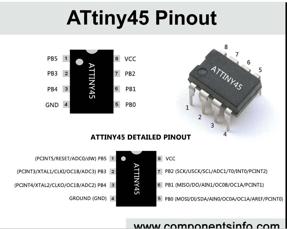
Attiny 45:
ATtiny45: Small AVR microcontroller with 4KB Flash, 6 I/O pins, low power, suitable for compact embedded projects, programmed using AVR-GCC.
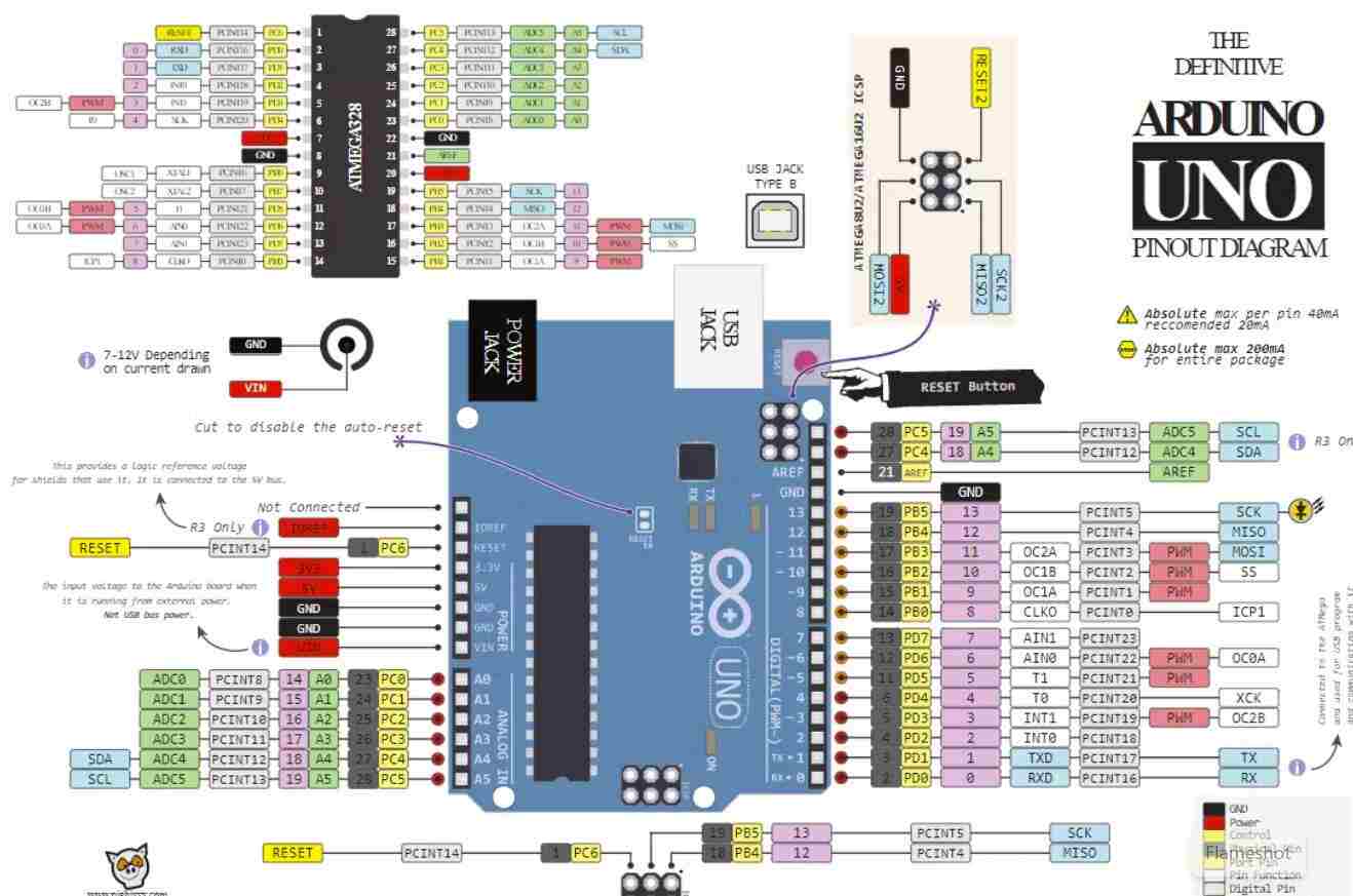
Arduino Uno :
Arduino UNO, featuring ATmega328P, offers 14 digital I/O pins (6 PWM), 6 analog inputs, 16MHz resonator, USB, power jack, ICSP header, and reset button—complete microcontroller support.
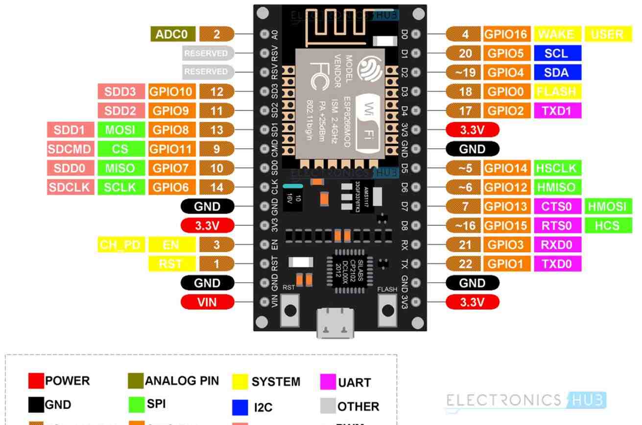
Esp 8266:
ESP8266EX excels in industrial settings with wide temperature range, integrated features, minimal external components, ensuring reliability, compactness, and robust performance.
I have programmed esp 8266 so check it out as you scroll down!!
As for the data sheet, view the group assignment here
THAT’S IT !!
Individual Assignment
Reading a Data sheet
Although, reading a data sheet was a group assignment, I read the data sheet for esp-32-wroom-32 here.
Here are some takeaways! :
MCU: Dual-core Tensilica Xtensa LX6 for efficiency.
Wireless: 802.11 b/g/n WiFi, integrated BLE for short-range.
Interfaces: GPIO, I2C, SPI, UART, ADC for sensors.
Memory: Flash for program/data, RAM for execution/storage.
Security: Secure Boot, hardware-accelerated cryptography.
Power: Low-power modes, deep sleep for ultra-low consumption.
Voltage: Wide range support.
Form Factor: Compact module.
Development: Espressif SDK, Arduino IDE compatibility.
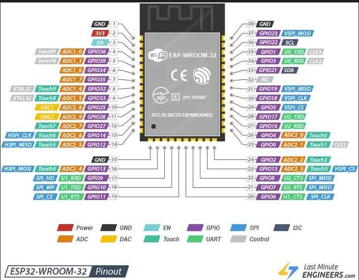
Here is the pinout for esp32 wroom-32
Programming
Final Project Board draft
I decided to try making my final project board this week itself only. So I used Kicad to make my board.
Earlier this week I made a sample circuit drawing for my FP:
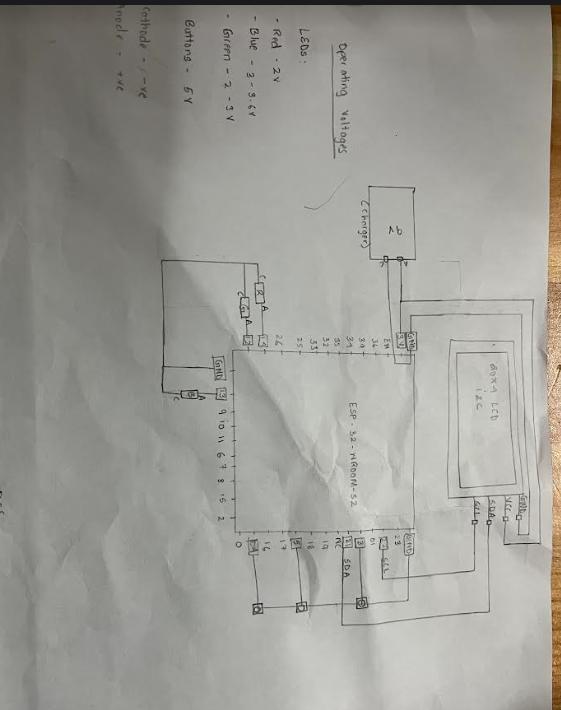
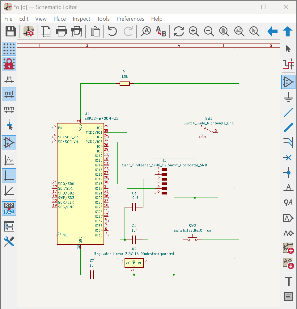
So here is how the 1st draft looked like:
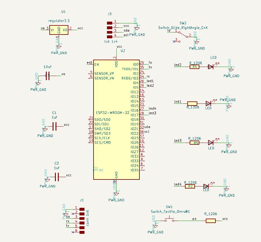
After receiving some feedbacks from my friends and instructors, this is how it looks:
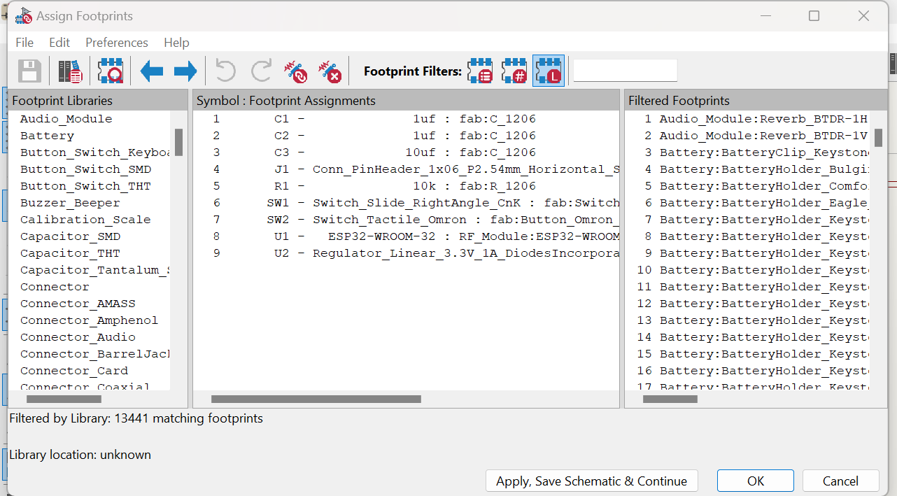
Don’t forget to assign footprints!!:
Connecting the components:

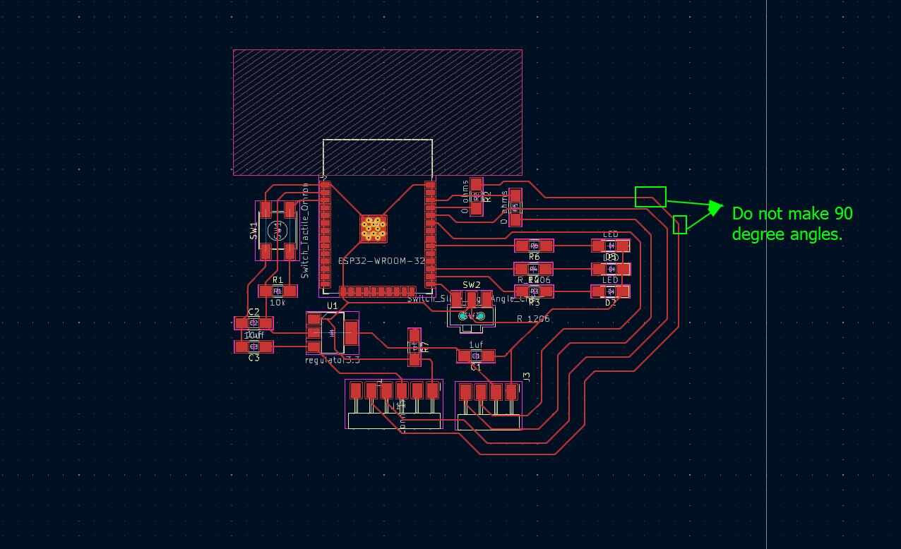
I wanted to add another button so I edited a bit:

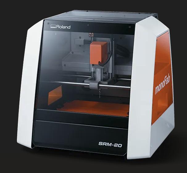
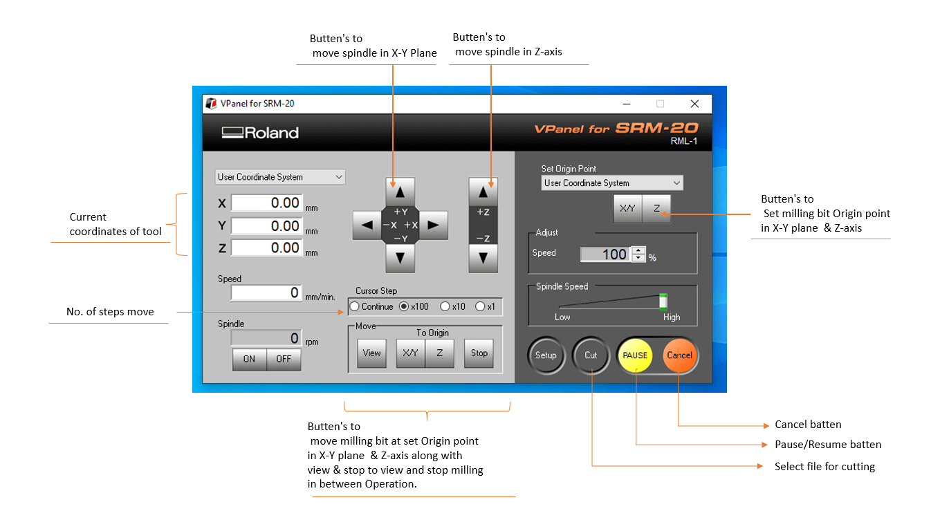
For miling, I am going to use Roland SRM 20 miling machine.
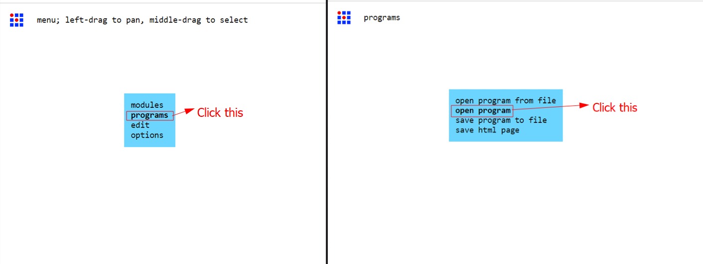
I am going to use Mods for converting the svg file to rml file like this:
In Mods right click -> Programs -> Open Program -> Roland (SRM-20 mill 2D PCB)-> Select png/svg

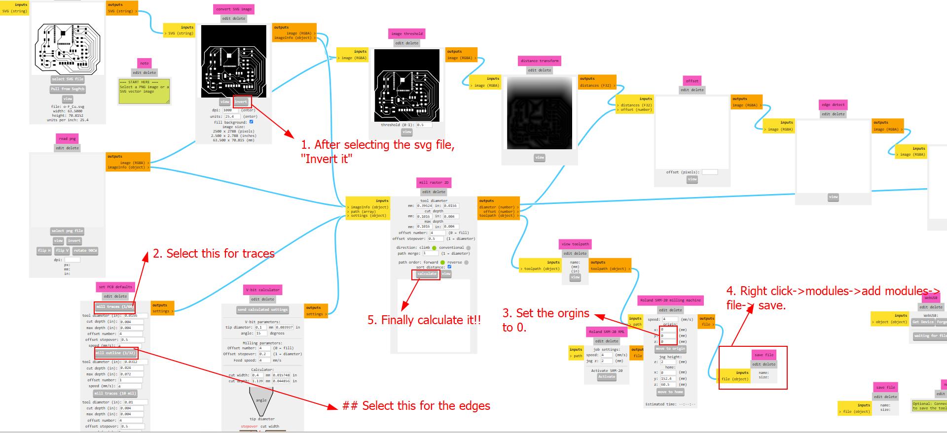
For making PCB Boards we have to set this setting:
Printing!

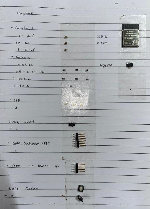
Here is the component list!
Soldering!!
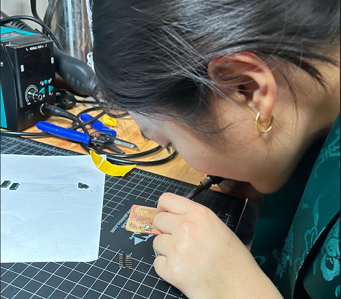
This is how it looks!

NOW LET’S TEST IT AND THEM PROGRAMME IT !
Firstly, download the esp 32 boards using this link:
https://raw.githubusercontent.com/espressif/arduino-esp32/gh-pages/package_esp32_index.json
Then include the esp 32 wroom 32 like this:

To test it, I used the blink code from arduino ide and this is how it turned out!

NOW, I used the button example to control 2 leds using a tactile push button like this:

Here is how it looks!
Quentorres
So I decided to programme my quentorres board from week 4. Due to limited time, I did the same thing with the quentorres board like my FP board.
To learn how to download and test the quentorres, view my week 4’s assignment here
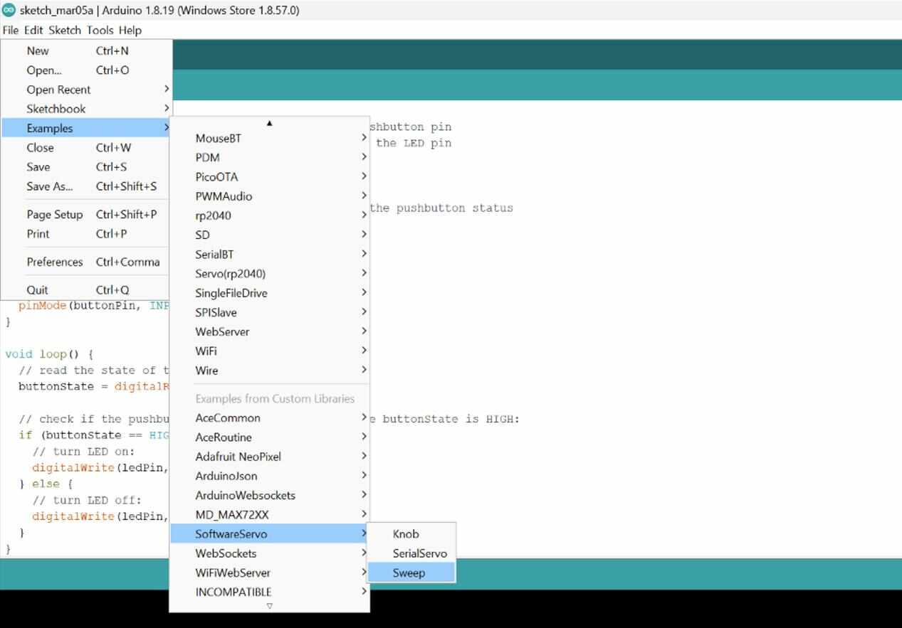
Now Select the button code from arduino ide like this:

Now code!

code:
const int buttonPin = 27;     // the number of the pushbutton pin
const int ledPin =  1;      // the number of the LED pin

// variables will change:
int buttonState = 0;         // variable for reading the pushbutton status

void setup() {
  // initialize the LED pin as an output:
  pinMode(ledPin, OUTPUT);
  // initialize the pushbutton pin as an input:
  pinMode(buttonPin, INPUT);
}

void loop() {
  // read the state of the pushbutton value:
  buttonState = digitalRead(buttonPin);

  // check if the pushbutton is pressed. If it is, the buttonState is HIGH:
  if (buttonState == HIGH) {
    // turn LED on:
    digitalWrite(ledPin, HIGH);
  } else {
    // turn LED off:
    digitalWrite(ledPin, LOW);
  }
}
Here is how it turned out!!
Esp8266
ESP8266: Wi-Fi module for IoT projects, low-cost, and easy to program, enabling wireless connectivity for smart devices and applications.
Web server
I have already programmed an esp8266 last time when I was learning how to host a web server. Here is how you do it in brief:
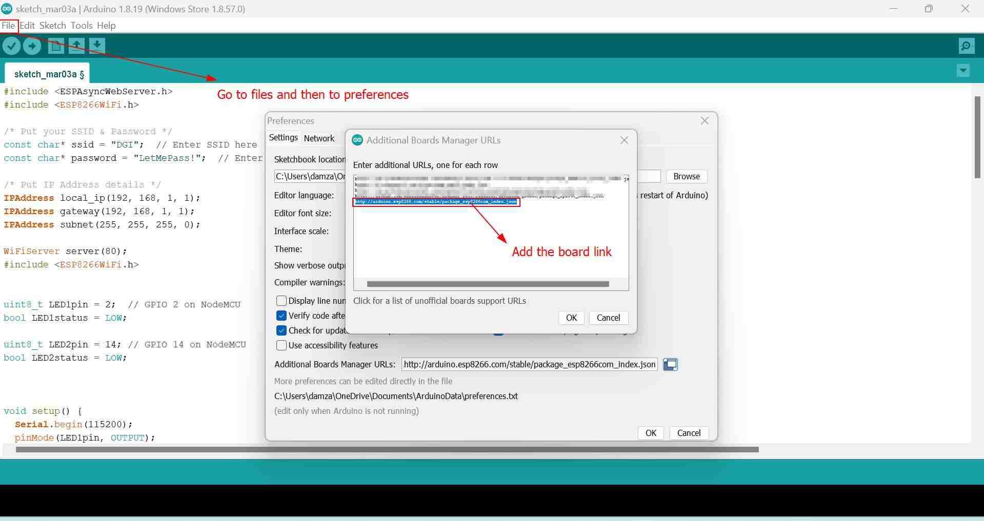
Firstly, you will need to add the boards:
http://arduino.esp8266.com/stable/package_esp8266com_index.json
Then download these libraries
Arduino Uno WiFi Dev Ed
Esp8266WiFi
asyncwebserver
Like this :
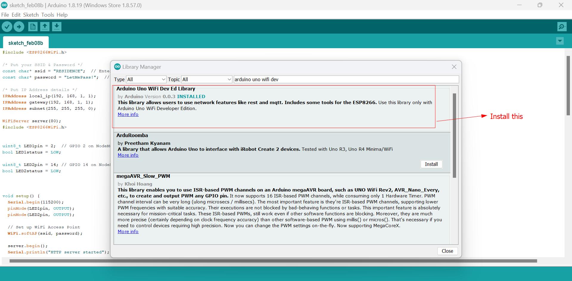
Don’t forget to add all the libraries!!
Now code!!

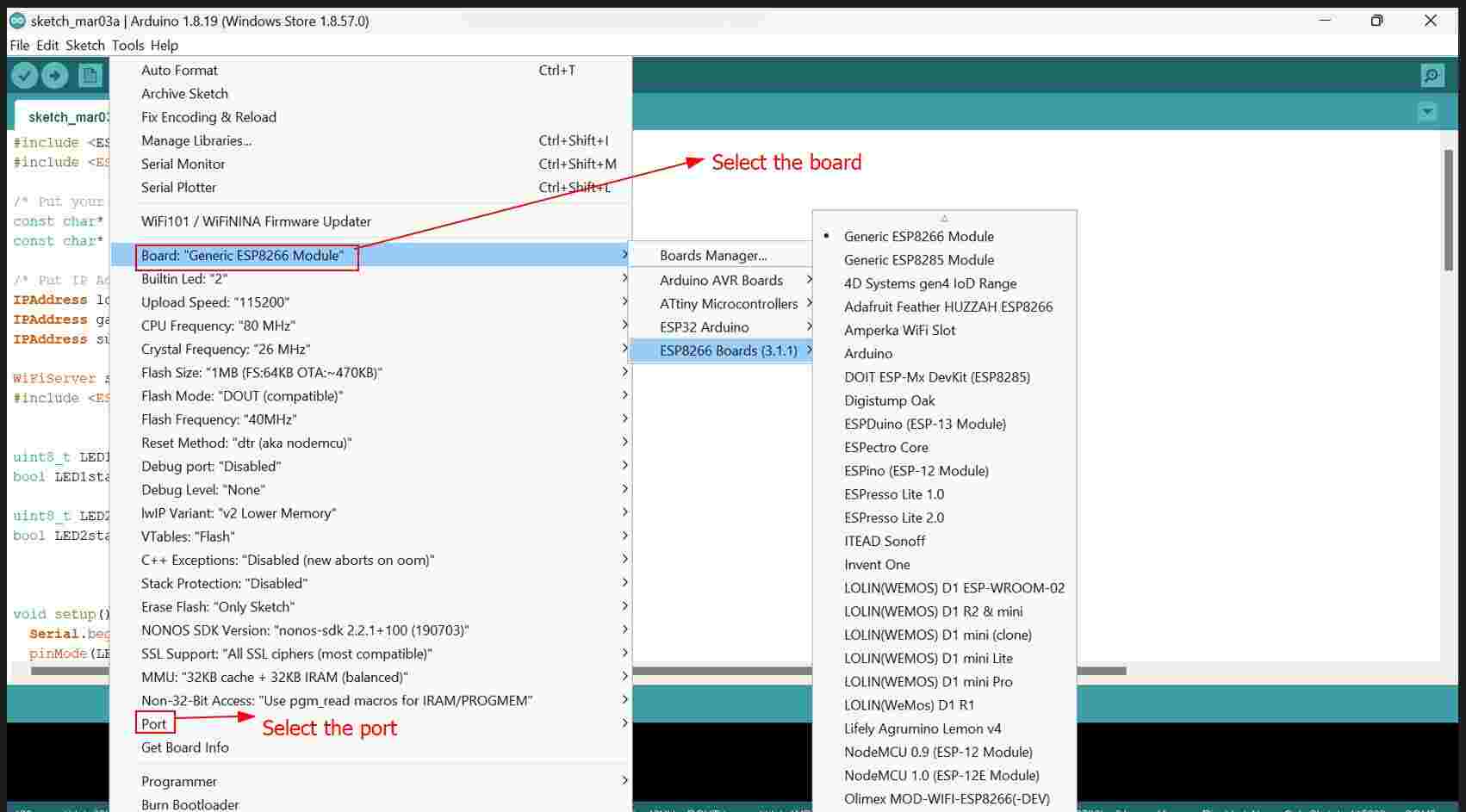
Before uploading, don’t forget to select the port and the boards
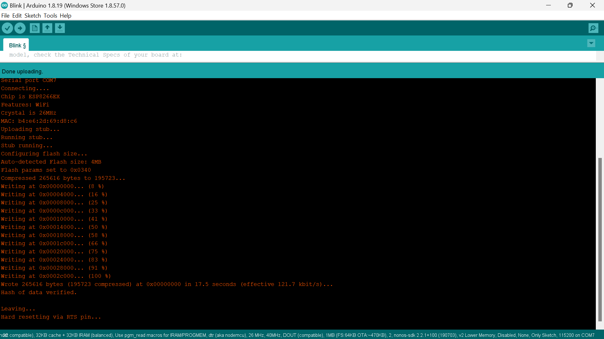
Uploading!
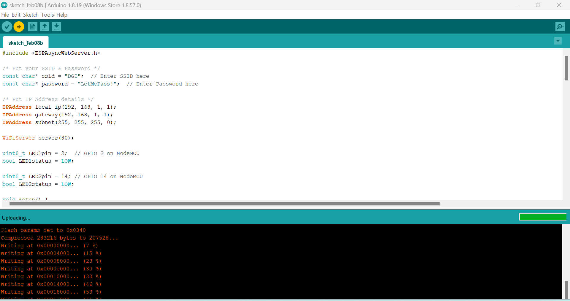
This is how it should look when you finish uploading the code:
Code:
#include <ESPAsyncWebServer.h>
#include <ESP8266WiFi.h>

/* Put your SSID & Password */
const char* ssid = "DGI";  // Enter SSID here
const char* password = "LetMePass!";  // Enter Password here

/* Put IP Address details */
IPAddress local_ip(192, 168, 1, 1);
IPAddress gateway(192, 168, 1, 1);
IPAddress subnet(255, 255, 255, 0);

WiFiServer server(80);
#include <ESP8266WiFi.h>


uint8_t LED1pin = 2;  // GPIO 2 on NodeMCU
bool LED1status = LOW;

uint8_t LED2pin = 14; // GPIO 14 on NodeMCU
bool LED2status = LOW;


void setup() {
  Serial.begin(115200);
  pinMode(LED1pin, OUTPUT);
  pinMode(LED2pin, OUTPUT);

  // Set up WiFi Access Point
  WiFi.softAP(ssid, password);

  server.begin();
  Serial.println("HTTP server started");
}

void loop() {
  WiFiClient client = server.available();  // Listen for incoming clients

  if (client) {
    Serial.println("New client connected");
    String currentLine = "";

    while (client.connected()) {
      if (client.available()) {
        char c = client.read();
        currentLine += c;

        if (c == '\n') {
          if (currentLine.length() == 0) {
            break;
          } else {
            if (currentLine.indexOf("GET /led1on") != -1) {
              LED1status = HIGH;
            } else if (currentLine.indexOf("GET /led1off") != -1) {
              LED1status = LOW;
            } else if (currentLine.indexOf("GET /led2on") != -1) {
              LED2status = HIGH;
            } else if (currentLine.indexOf("GET /led2off") != -1) {
              LED2status = LOW;
            }

            client.println("HTTP/1.1 200 OK");
            client.println("Content-type:text/html");
            client.println("Connection: close");
            client.println();

            client.println(SendHTML(LED1status, LED2status));

            break;
          }
          currentLine = "";
        }
      }
    }

    client.stop();
    Serial.println("Client disconnected");
  }

  digitalWrite(LED1pin, LED1status);
  digitalWrite(LED2pin, LED2status);
}

String SendHTML(uint8_t led1stat, uint8_t led2stat) {
  String ptr = "<!DOCTYPE html> <html>\n";
  ptr += "<head><meta name=\"viewport\" content=\"width=device-width, initial-scale=1.0, user-scalable=no\">\n";
  ptr += "<title>LED Control</title>\n";
  ptr += "<style>html { font-family: Helvetica; display: inline-block; margin: 0px auto; text-align: center;}\n";
  ptr += "body{margin-top: 50px;} h1 {color: #444444;margin: 50px auto 30px;} h3 {color: #444444;margin-bottom: 50px;}\n";
  ptr += ".button {display: block;width: 80px;background-color: #3498db;border: none;color: white;padding: 13px 30px;text-decoration: none;font-size: 25px;margin: 0px auto 35px;cursor: pointer;border-radius: 4px;}\n";
  ptr += ".button-on {background-color: #3498db;}\n";
  ptr += ".button-on:active {background-color: #2980b9;}\n";
  ptr += ".button-off {background-color: #34495e;}\n";
  ptr += ".button-off:active {background-color: #2c3e50;}\n";
  ptr += "p {font-size: 14px;color: #888;margin-bottom: 10px;}\n";
  ptr += "</style>\n";
  ptr += "</head>\n";
  ptr += "<body>\n";
  ptr += "<h1>ESP32 Web Server</h1>\n";
  ptr += "<h3>Using Access Point(AP) Mode</h3>\n";\" href=\"/led2off\">OFF</a>\n";
  } else {
    ptr += "<p>LED2 Status: OFF</p><a class=\"button button-on\" href=\"/led2on\">ON</a>\n";
  }

  ptr += "</body>\n";
  ptr += "</html>\n";
  return ptr;
}
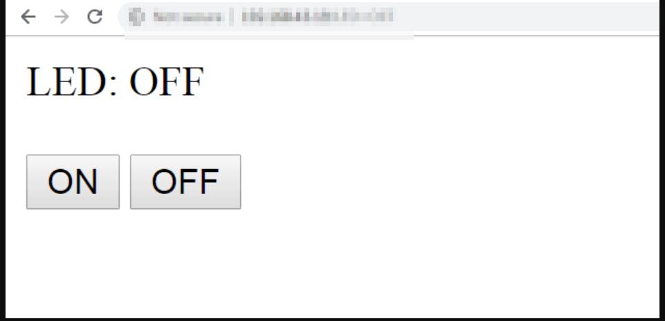
The web page should look something like this( PS: YOU CAN CHANGE THE LAYOUT AS YOU WISH JUST LIKE ME!!)
Blinking
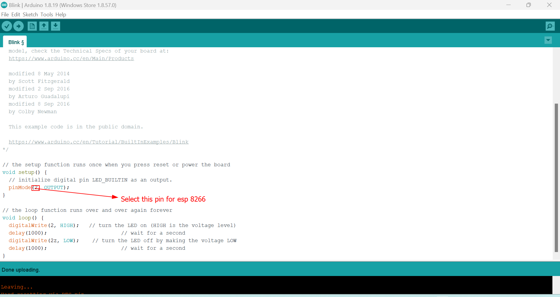
I used the blink example in arduino ide.
Like this:
Code:
void setup() {
  // initialize digital pin LED_BUILTIN as an output.
  pinMode(2, OUTPUT);
}

// the loop function runs over and over again forever
void loop() {
  digitalWrite(LED_BUILTIN, HIGH);   // turn the LED on (HIGH is the voltage level)
  delay(1000);                       // wait for a second
  digitalWrite(LED_BUILTIN, LOW);    // turn the LED off by making the voltage LOW
  delay(1000);                       // wait for a second
}
Here is the output!
Prefab board
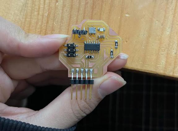
I programmed this during prefab and I was able to move a servo after several tries and after testing a lot of times… SO it was a really good start and I learnt a lot from it!
Here is the soldered board:
Using the example code from Arduino Ide :
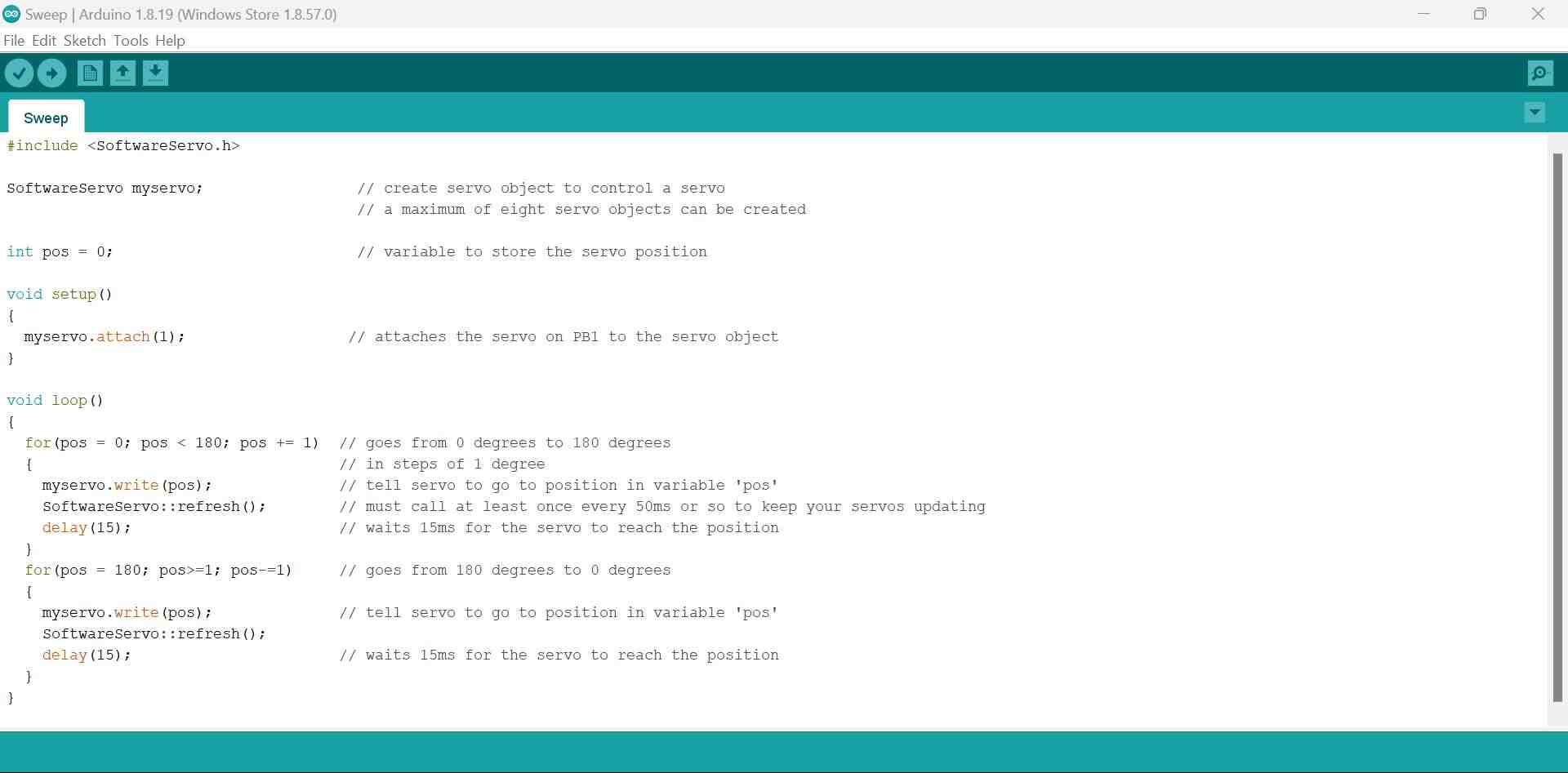
Code:
#include <SoftwareServo.h>

SoftwareServo myservo;                 // create servo object to control a servo
                                       // a maximum of eight servo objects can be created

int pos = 0;                           // variable to store the servo position

void setup()
{
  myservo.attach(1);                  // attaches the servo on PB1 to the servo object
}

void loop()
{
  for(pos = 0; pos < 180; pos += 1)  // goes from 0 degrees to 180 degrees
  {                                  // in steps of 1 degree
    myservo.write(pos);              // tell servo to go to position in variable 'pos'
    SoftwareServo::refresh();        // must call at least once every 50ms or so to keep your servos updating
    delay(15);                       // waits 15ms for the servo to reach the position
  }
  for(pos = 180; pos>=1; pos-=1)     // goes from 180 degrees to 0 degrees
  {
    myservo.write(pos);              // tell servo to go to position in variable 'pos'
    SoftwareServo::refresh();
    delay(15);                       // waits 15ms for the servo to reach the position
  }
}
OUTPUT!!
I documented this while I was trying out during prefab itself only!!
Compressions:
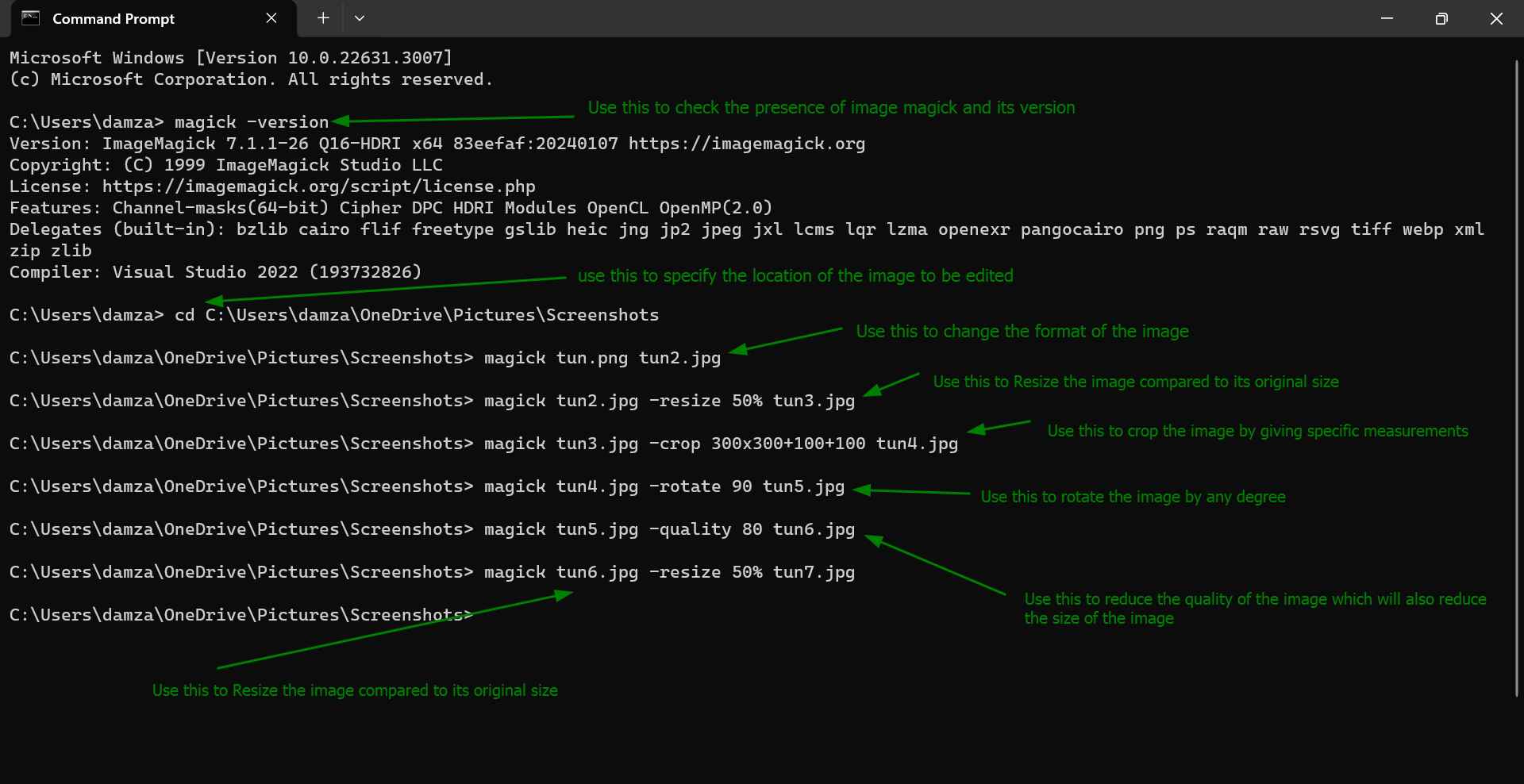
Imagemagick
I used image magick for image compression. Here are some commands I used for compression:
Ffmpeg
I used ffmpeg for video compression. Here are some commands I used:
- Basic Conversion:
Convert a video file to another format:
ffmpeg -i input.mp4 output.avi
- Changing Video Resolution:
Resize a video:
ffmpeg -i input.mp4 -vf scale=640:480 output.mp4
- Extracting Audio:
Extract audio from a video file:
ffmpeg -i input.mp4 -vn -c:a copy output.mp3
Files
THAT’S IT FOR THIS WEEK!!
HAVE A NICE DAY!!!