Output Devices
Group assignment:
-
Measure the power consumption of an output device.
-
Document your work on the group work page and reflect on your individual page what you learned.
Individual assignment:
- Add an output device to a microcontroller board you’ve designed and program it to do something.
Learning outcomes
Demonstrate workflows used in controlling an output device(s) with MCU board you have designed.
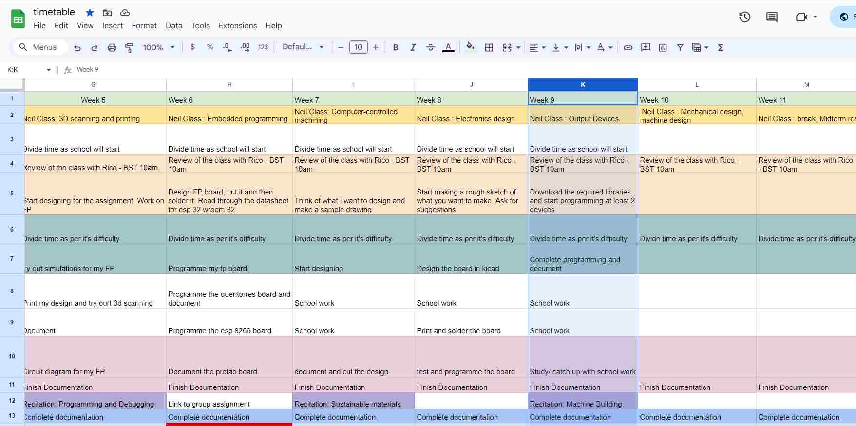
As usual here is my schedule:
Hero Shot

Group Assignment
Measuring power consumption of LED
Measuring power consumption is an important part of determining the energy efficiency and performance of electrical or electronic devices.
Power consumption is the rate at which energy is consumed by a device and is commonly measured in watts (W) or milliwatts (mW).
To measure power use, you’ll need a power meter, also known as a wattmeter. The basic concept is to measure the current (A) passing through a device and the voltage (V) across it. With these readings, you can determine power using the following formula:
Power (P) = Voltage (V) x Current (I).
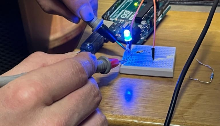
For our group work this week, we measured the power consumption of an LED.
Note : The circuit will be closed through the multimeter if we don’t connect it correctly and consistently on a high scale, or where the protection fuse is located (usually 10A). This means that we must constantly measure in series.
Tools Required:
-
Multimeter equipped with an ammeter
-
Source of power (like a battery or power supply)
-
LED configuration (resistors, wire connections, and LEDs)
Following the assembly of all the parts, we linked them in series, keeping the Arduino’s primary power supply attached to the CPU.
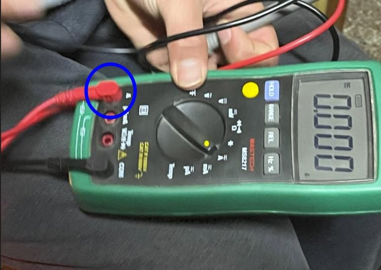
First we have to turn the multimeter dial to the Ammeter mode.
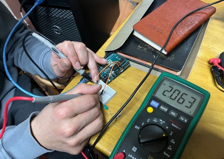
Next, we measured the CPU’s current without using any resistors or LEDs, and we found that it was about 2.063 A.
Next, we gave the LED a try:
-
Attach the power source’s positive connector to the LED’s anode (+).
-
Attach the LED’s cathode (-) to the multimeter’s positive (red) probe.
-
To complete the circuit through the multimeter, connect its negative (black) probe to the power source’s negative terminal.
-
After turning on the power supply, let the LED light up completely.
-
Take note of the multimeter’s current reading and record it. This is the LED’s operational current.
Compute the Power Usage:
The formula P = V * I, where V is the voltage and I is the current, can be used to determine the power usage if you know the voltage across the LED setup, which is typically 3V for many conventional LEDs.
P = 3V * 0.01A = 0.03W or 30mW, for instance, if the voltage across the LED is 3V and the measured current is 10mA (0.01A).
Repeat and Average:
Optional!!
You can compute the average current and power usage by repeating the measuring procedure several times for more precise results.
Click here to view the group assignment
Individual Assignment
So for this week, I have tried quite a few number of output devices. SO I will take you through what I have done this week!!!
But before proceeding to the programming part, let’s add the libraries!! And here is how you do it:
So for the devices I used, here is the list of required libraries:
- Adafruit SSD1306 (All packages)
- LiquidCrystal_I2C
- ESP32Servo
Adafruit SSD1306
SO firstly for the Adafruit SSD1306 library (which will be required to programme the OLED.) go to Sketches -> Include Libraries -> Manage Libraries -> Search “Adafruit SSD1306” or “oled” like this:

LiquidCrystal_I2C
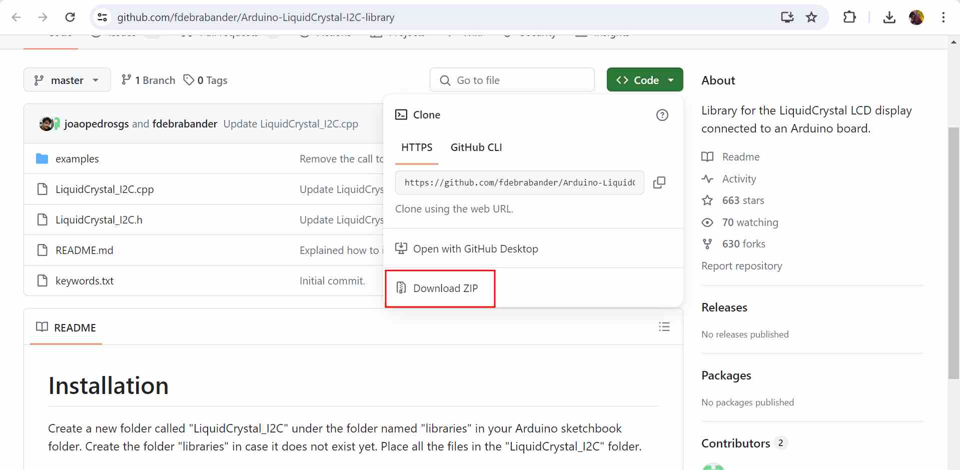
Now for the LiquidCrystal_I2C library, we will need to download a zip file from this link:
https://github.com/fdebrabander/Arduino-LiquidCrystal-I2C-library
Go to the link and do this to download the zip file:
After downloading the file, extract it and place in the libraries folder in Arduino folder:
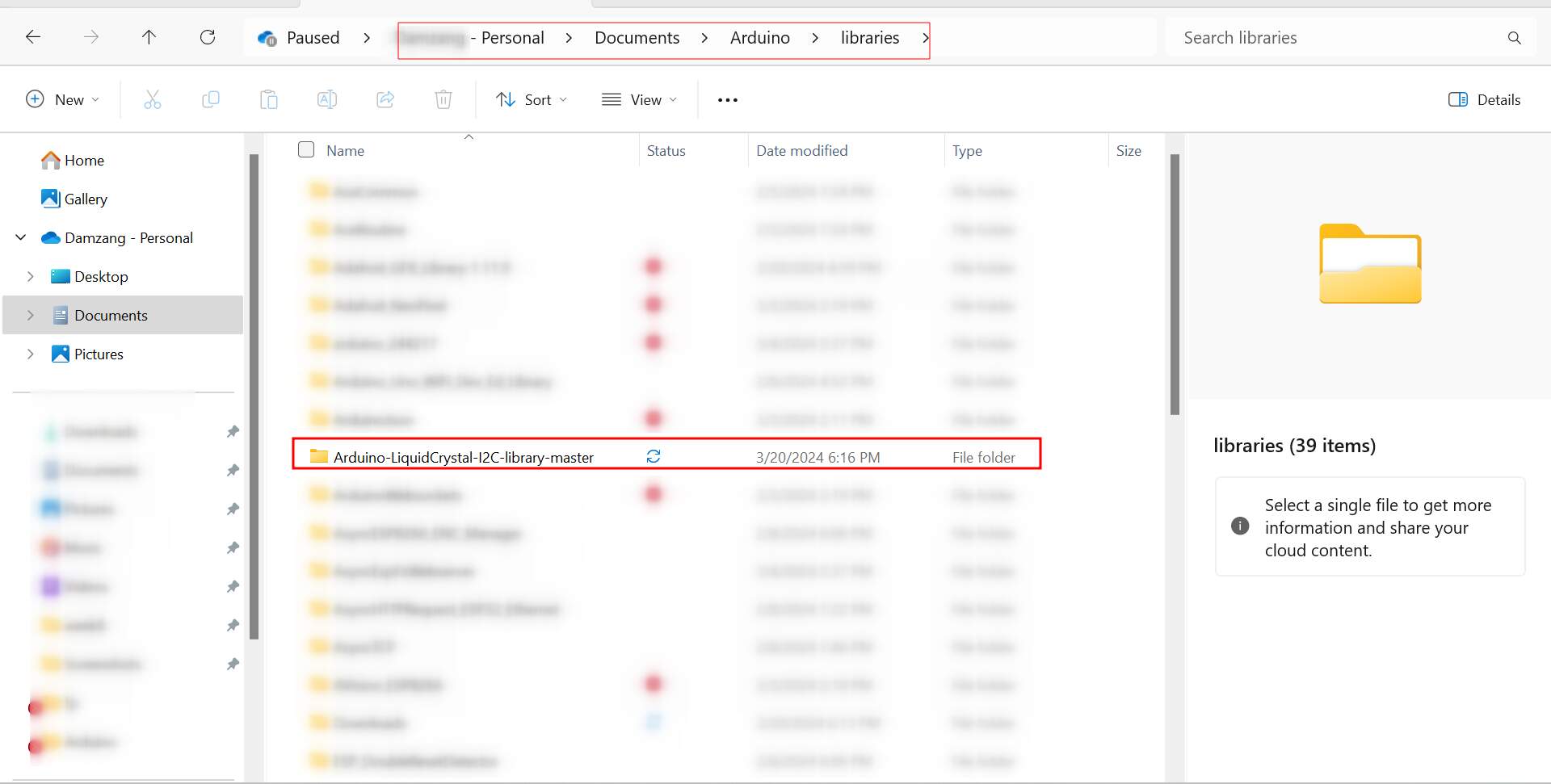
We don’t need to include the library soince it will be already included if we place it in the libraries folder.
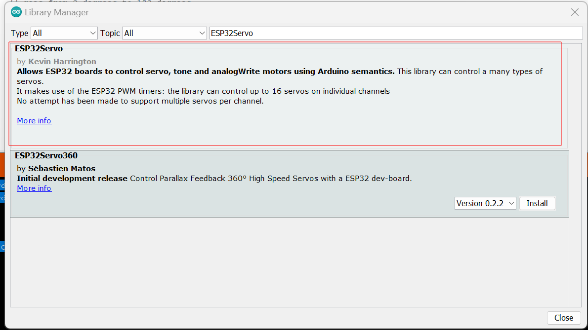
ESP32Servo
Now for the ESP32Servo, go to Sketches -> Include Libraries -> Manage Libraries -> Search “ESP32Servo” and install the latest version like this:
Board: For this week’s assignment, I will be using the board I fabricated during week 8. I will be using this PCB board for the assignments that follow!!
NOW LET’S PROGRAMME!! Let’s start with the servo.
Servo
Servo motor

Servo Motor: A motor that uses feedback control to precisely control its position, speed, and acceleration. Commonly used in robotics and automation.
Programming
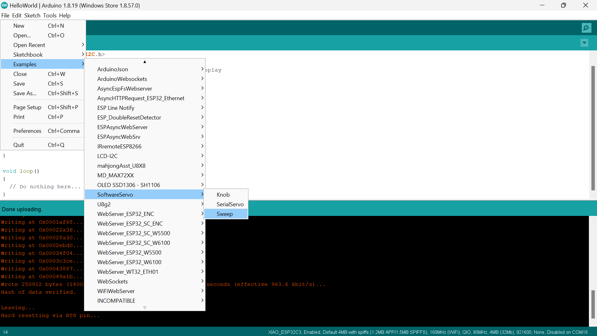
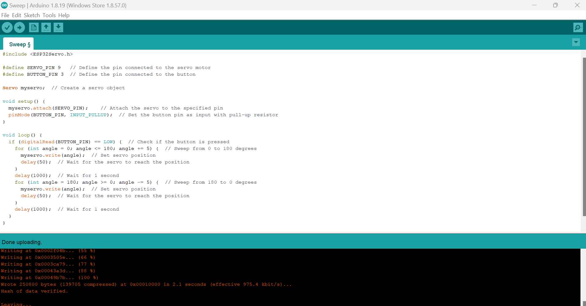
Firstly, I tried the sweep example code to test the servo and then controlled it using a push button. SO here is how you can do the sweep code:
Here is how it should look:
Then for the button and servo here is the code:
REMEMBER TO SELECT THE PORTS AND THE CORRECT BOARD!!!
As for the connection, make sure to connect the pins to VCC, GND and a Control Pin correctly.
Here is a video of how it turned out!!
DC Motor

DC Motor: A motor that runs on direct current (DC) electricity, converting electrical energy into mechanical rotation. Widely used in various applications such as fans, toys, and small appliances.
Since DC Motors only have 2 pins; VCC and GND, I turned it on simply by connecting it to the VCC and GND of my board. (We didn’t have drivers so I could not control it)
SO here is a video of how it looks:
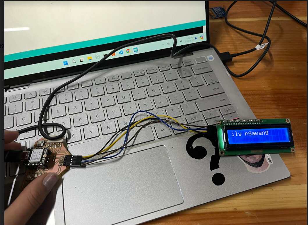
I2C 16x2 LCD
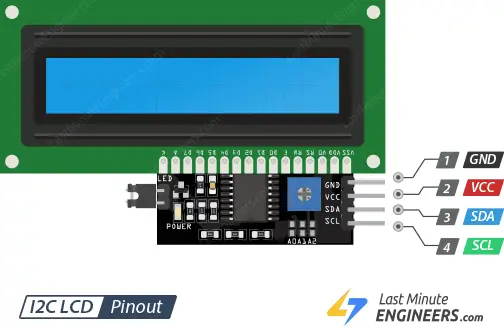
I2C 16x2 LCD is a Liquid Crystal Display with 16 characters per line, utilizing I2C communication protocol for data exchange.
Programming
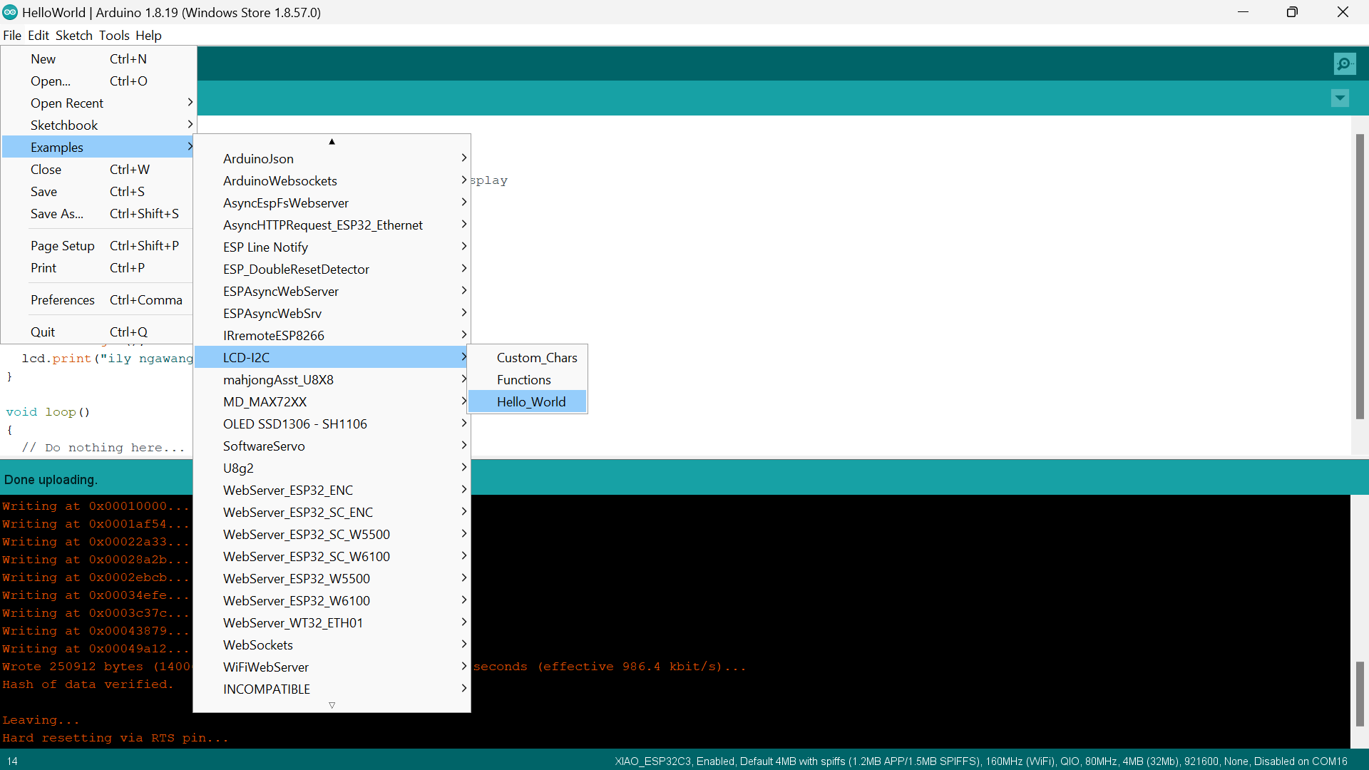
After adding the library, go to Files -> Examples -> LCD-I2C -> Hello_world, for testing the lcd like this:
After testing the lcd, I edited the characters that are to be displayed. Here is how the code looks:

Here is how it turned out!!
After that, I decided to move on to the OLED display:
Oled
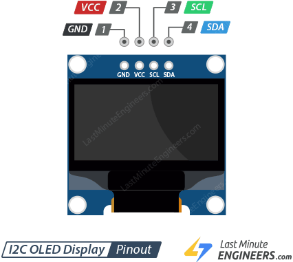
OLED (Organic Light Emitting Diode) is a display technology where organic compounds emit light when an electric current passes through them. OLED displays offer high contrast ratios, wide viewing angles, and are commonly found in smartphones, TVs, and wearable devices due to their thinness and energy efficiency compared to traditional LCDs.
Programming
Since we already downloaded the library, we can directly go to Files -> Examples -> Adafruit SSD1306 -> OLED_feathering for testing the oled like this:

Then, I used Chatgpt, to generate some fun codes for me!
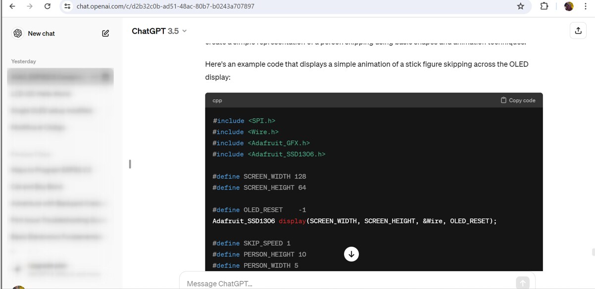
Here is how you can give precise prompts to the ai:

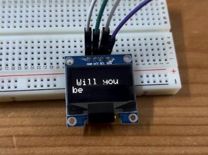
I tried multiple things with the oled and firstly I decided to display some random letters like this:
Here is how the explanation will look like :

After that, I decided to display scrolling humans and this is how it turned out:
I tried to modify the code but it didn’t really work that well, so I decided to make a obstacle game. At first, the I did not programme it to be controlled by the push button. After programming the display to be controlled by the 2 push buttons, I was able to play the game and it also displays the score!!!
Here is the code:
#include <SPI.h>
#include <Wire.h>
#include <Adafruit_GFX.h>
#include <Adafruit_SSD1306.h>

#define SCREEN_WIDTH 128
#define SCREEN_HEIGHT 64

#define OLED_RESET    -1
Adafruit_SSD1306 display(SCREEN_WIDTH, SCREEN_HEIGHT, &Wire, OLED_RESET);

#define PLAYER_WIDTH 10
#define PLAYER_HEIGHT 10
#define OBSTACLE_WIDTH 10
#define OBSTACLE_HEIGHT 10

#define PLAYER_SPEED 1
#define OBSTACLE_SPEED 1

#define BUTTON_PIN_LEFT 2   // Define the pin for the left button
#define BUTTON_PIN_RIGHT 3  // Define the pin for the right button

int playerX, playerY;
int obstacleX, obstacleY;
int score;

void setup() {
  randomSeed(analogRead(0)); // Initialize random seed
  pinMode(BUTTON_PIN_LEFT, INPUT_PULLUP);  // Set the button pin as input with internal pull-up resistor
  pinMode(BUTTON_PIN_RIGHT, INPUT_PULLUP); // Set the butto Q n pin as input with internal pull-up resistor

  if (!display.begin(SSD1306_SWITCHCAPVCC, 0x3C)) {
    Serial.println(F("SSD1306 allocation failed"));
    for (;;);
  }
  display.display();
  delay(2000);
  display.clearDisplay();

  playerX = (SCREEN_WIDTH - PLAYER_WIDTH) / 2;
  playerY = SCREEN_HEIGHT - PLAYER_HEIGHT;
  obstacleX = random(SCREEN_WIDTH - OBSTACLE_WIDTH);
  obstacleY = 0;
  score = 0;
}

void loop() {
  display.clearDisplay();

  // Move player
  movePlayer();

  // Move obstacle
  moveObstacle();

  // Check collision
  if (checkCollision()) {
    display.setTextSize(1);
    display.setTextColor(SSD1306_WHITE);
    display.setCursor(20, 20);
    display.println("Game Over!");
    display.setCursor(30, 40);
    display.print("Score: ");
    display.println(score);
    display.display();
    delay(5000); // Delay for 5 seconds before restarting the game
    resetGame();
  }

  // Increase score
  score++;

  // Draw player
  display.fillRect(playerX, playerY, PLAYER_WIDTH, PLAYER_HEIGHT, SSD1306_WHITE);

  // Draw obstacle
  display.fillRect(obstacleX, obstacleY, OBSTACLE_WIDTH, OBSTACLE_HEIGHT, SSD1306_WHITE);

  display.display();
  delay(50);
}

void movePlayer() {
  if (digitalRead(BUTTON_PIN_LEFT) == LOW && playerX > 0) {
    playerX -= PLAYER_SPEED;
  }
  if (digitalRead(BUTTON_PIN_RIGHT) == LOW && playerX < SCREEN_WIDTH - PLAYER_WIDTH) {
    playerX += PLAYER_SPEED;
  }
}

void moveObstacle() {
  obstacleY += OBSTACLE_SPEED;
  if (obstacleY > SCREEN_HEIGHT) {
    obstacleX = random(SCREEN_WIDTH - OBSTACLE_WIDTH);
    obstacleY = 0;
  }
}

bool checkCollision() {
  if (playerX + PLAYER_WIDTH >= obstacleX && playerX <= obstacleX + OBSTACLE_WIDTH &&
      playerY + PLAYER_HEIGHT >= obstacleY && playerY <= obstacleY + OBSTACLE_HEIGHT) {
    return true;
  }
  return false;
}

void resetGame() {
  playerX = (SCREEN_WIDTH - PLAYER_WIDTH) / 2;
  playerY = SCREEN_HEIGHT - PLAYER_HEIGHT;
  obstacleX = random(SCREEN_WIDTH - OBSTACLE_WIDTH);
  obstacleY = 0;
  score = 0;
}
Code Explanation:
SO firstly I started by including the ‘SPI.h’ and ‘Wire.h’ for SPI and I2C communication. ‘Adafruit_GFX.h’ and ‘Adafruit_SSD1306.h’ for OLED display control.
Then the ‘Adafruit_SSD1306 display(…, &Wire, OLED_RESET);’ initializes the OLED display using I2C protocol.
Then the button initialization using ‘button pinMwode(BUTTON_PIN_LEFT, INPUT_PULLUP);’ and ‘pinMode(BUTTON_PIN_RIGHT, INPUT_PULLUP);’ configure buttons with internal pull-up resistors.
Then the ‘display.begin(SSD1306_SWITCHCAPVCC, 0x3C);’ initializes the display with I2C address ‘0x3C.’
IN the main loop:
The ‘display.clearDisplay();’ and ‘display.display();’ clear and update the OLED display.
If a collusion is detected, it displays “Game Over” and resets the game.
The ‘digitalRead(BUTTON_PIN_LEFT)’ and ‘digitalRead(BUTTON_PIN_RIGHT)’ detect button presses to move the player.
Communication Protocols
I2C Protocol is used to communicate with the OLED display via the ‘Wire’ library and ‘display.begin()’ function.
Digital Read is used for reading button states with ‘digitalRead()’, which interfaces with the microcontroller’s GPIO pins.
I used ChatGPT for generating the code and the explanations and then for documenting, I rephrased the explanations according to my understanding!!
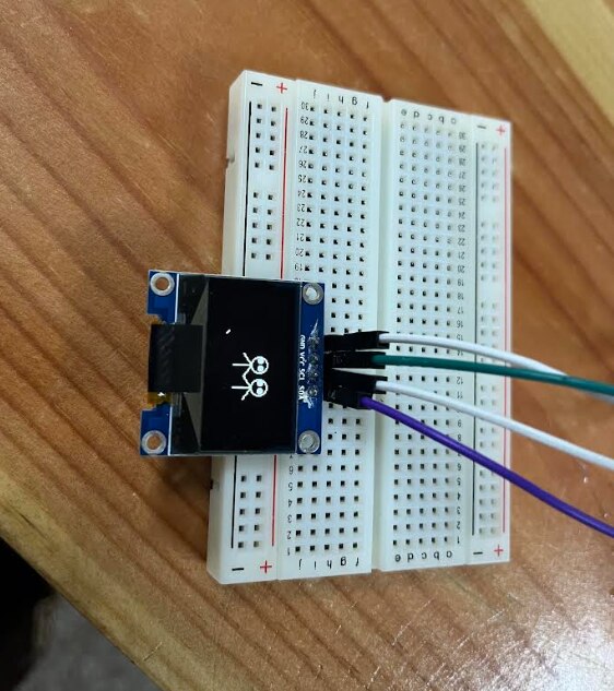
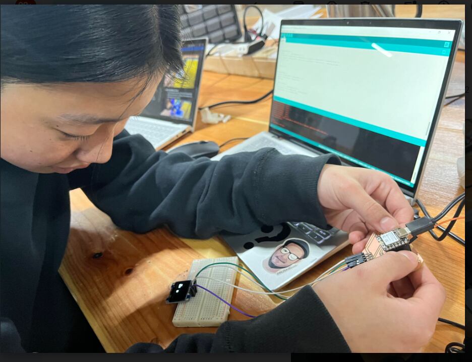
AND HERE IS THE OUTPUT!!!
NGAWANG TRYING OUT MY GAME!!!
Reflection
For this week, playing around with the code and being able to display something fun as well as interactive was really a new thing for me. I also leant a lot from the individual assignment and for the group assignment, I was able to learn a lot and one of the highlights would be learning how to use the multimeter. This week, I came across some issues with programming (mainly with wrong syntax and extra charcters), however I was able to troubleshoot them and get good outputs!
Files:
THAT’S IT FOR THIS WEEK!!
HAVE A NICE DAY