Week 8: Electronics Design
-
Group assignment:
-
Use the test equipment in your lab to observe the operation of a microcontroller circuit board (as a minimum, you should demonstrate the use of a multimeter and oscilloscope)
-
Document your work on the group work page and reflect what you learned on your individual page
-
-
Individual assignment:
-
Use an EDA tool to design a development board to interact and communicate with an embedded microcontroller
-
Navigation
- Preparation for the week
- Starting with Eagle
- How to Import an external Library into Eagle:
- Connecting an SPI device to a SEED XIAO RP2040
- Making the Schematic in Eagle
- PCB DESIGN
- Problems and Tribulations
- Machining and Soldering
- Programming
- Groupal Assignment
Preparation for the week:
The first step that I followed was to check into the inventory of the Fab Lab here in CiDi to see what kind of components were available for us to use.
Series where I realized that there were many of the things that I wanted to use that were not available in our lab so I had to see how to get them from other sources.
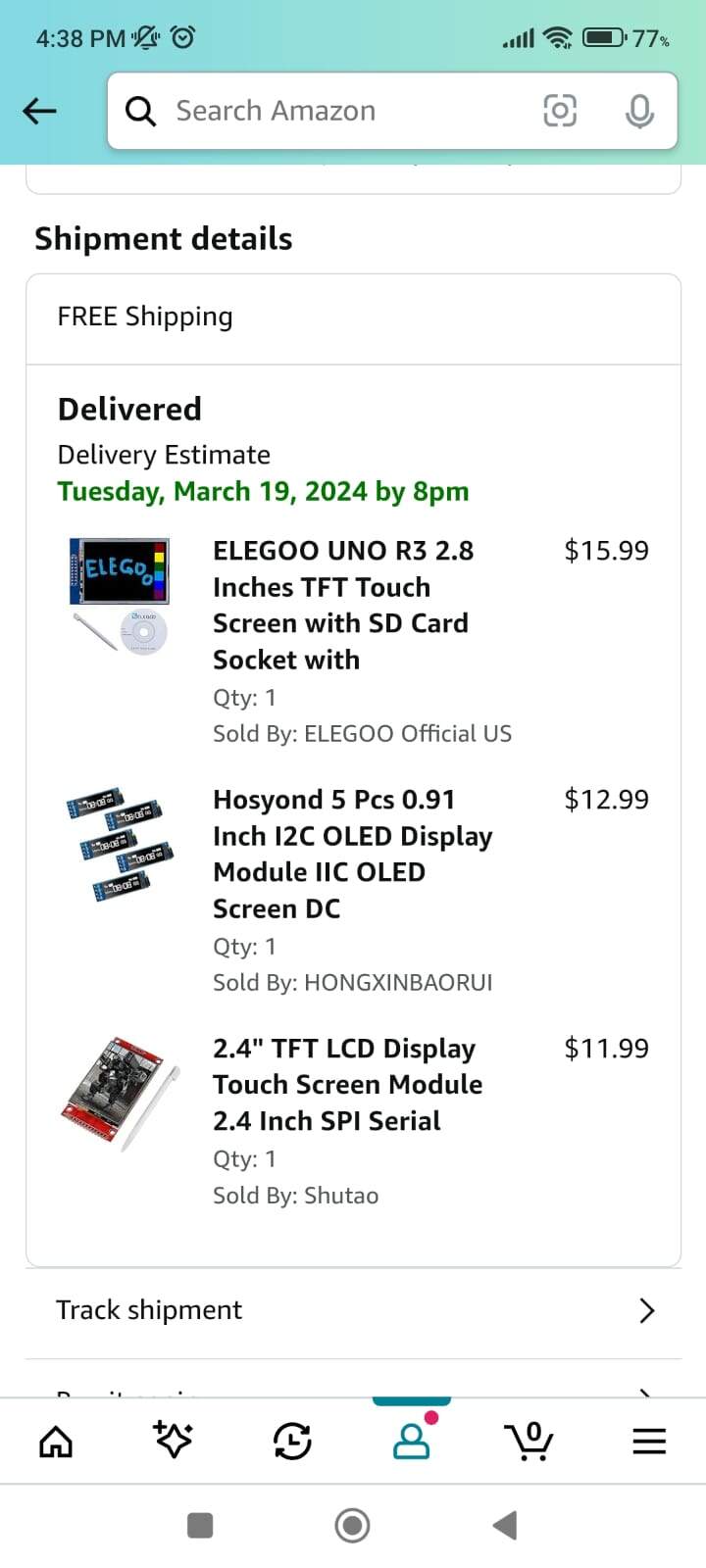
My plan was to use the ili9341 TFT display cuz I think it's going to help me with my final project by being that visual interface for my Bluebo. I finally decided to buy it from Amazon and just wait for it to arrive here. This is sadly a process that usually takes like a week or two so I knew that I was going to have other things done before this happened. I ordered some stuff from Amazon that wasn't readily available here in my country. The Raspberry Pi Pico (I will probably use this as my main microcontroller in the final project if possible), 2 different TFT screens with touch sensors and some OLEDs to test. You can see that order here. Like you can see, the date says March 19th, but that is for the Miami mailbox. The courier for it to get here usually takes another 5 days or so.

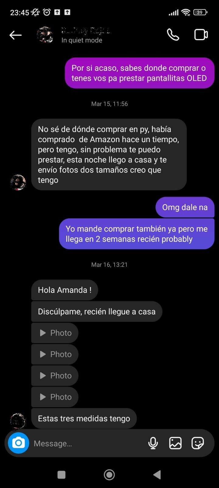
I had to start with something at least, so I went to friends around the community here in Paraguay to see if anyone had at least an OLED display to start testing some of it on this week. I know it's not the same but it does work a little like a TFT display does as well. Through Instagram I was able to contact someone that had some TFT displays available and was kind enough to lend them to me until I got mine that I ordered from Amazon.

Starting with Eagle
After that conundrum was solved, I went in and started to try to use Eagle, this is a program that I was a little familiar with cuz I used it before and I also know a little bit about how EDA works because of my background in electronics and I've been using Proteus before. This has been a while ago so I had to refresh my memory about all of the process and see if there were changes in the software that I was used to using.
I decided to try and create something like the Fab Xiao platform because it was recommended to us to start from there. I didn't want to just copy it tho, but build it with the changes that I needed for my personal use. So by grabbing some of the things of the model like the schematic and the library of the Xiao, and then I started to design my own board in Eagle.
Another thing I did before starting to design more in detail was installing the Fab library into my Eagle.
How to Import an external Library into Eagle:
-
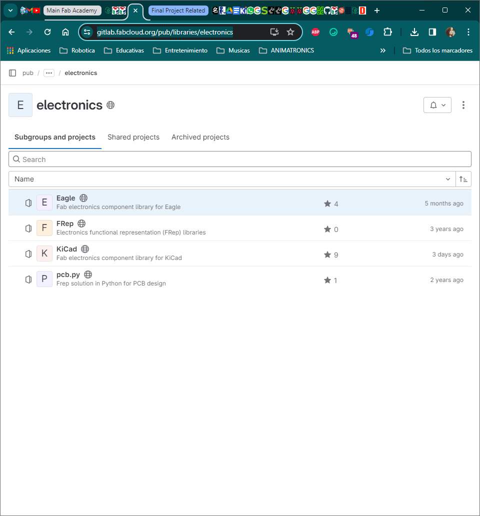
Downloading the library of the Fab Academy> https://gitlab.fabcloud.org/pub/libraries/electronics
-
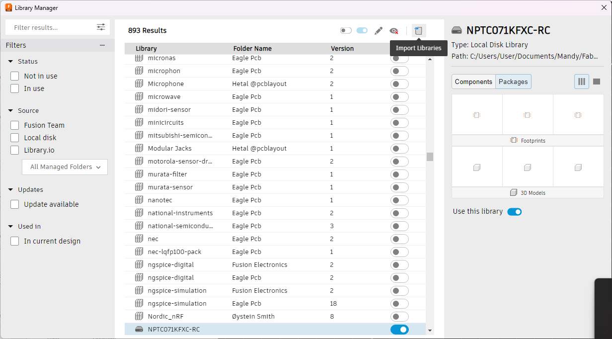
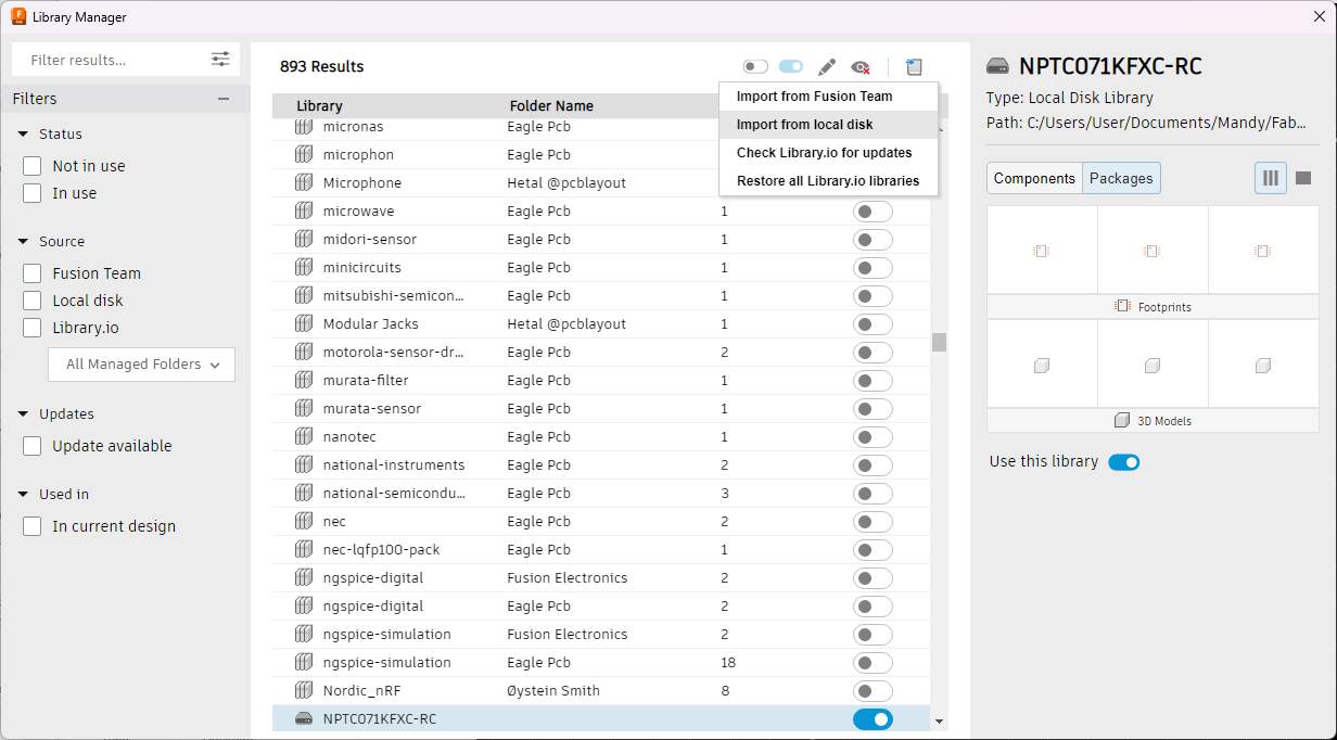
Opening Eagle, and going into the Library Manager
-
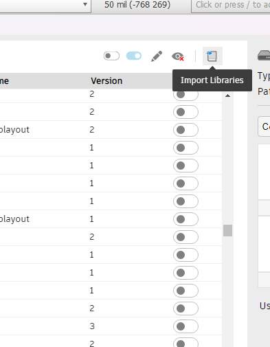
Going to the icon of import library and import from local disk
-
Selecting the library in your explorer

-
Search for the library in the manager, and make sure to turn it on so you can see it in your work area.

-
And done.
This is the same process that needs to be followed for any external library of components that are not really inside the Eagle software already.
Connecting an SPI device to a SEED XIAO RP2040
I started to research a little bit how to connect an SPI display (like the ILI8341 is) into the RP2040. I don't really like how the SEEED XIAO is built for these kinds of things because it is quite small in every sense and most of the pins that are available for use are used in this display only. I tried to go around it and I made a little table using information that I found in this pagethat was used with a Raspberry Pi Pico and crossed it over with what I needed in the Xiao rp2040.
|
ili9341 TFT Display Pin |
Raspberry Pi Pico |
SEED XIAO RP2040 |
|
VCC |
3.3V |
3.3V |
|
GND |
GND |
GND |
|
CS |
GP17 (SPI0 CSn) |
GP1 (CSn) |
|
RESET |
GP7 (SPI0 TX) |
GP6 (SCL/IIC) |
|
DC/RS |
GP6 (SPI0 SCK) |
GP7 (tx) |
|
SDI(MOSI) |
GP15 (SPI1 TX) |
GP3 (MOSI) |
|
SCK |
GP14 (SPI1 SCK) |
GP8 (SCK) |
|
LED |
3.3V |
5V |
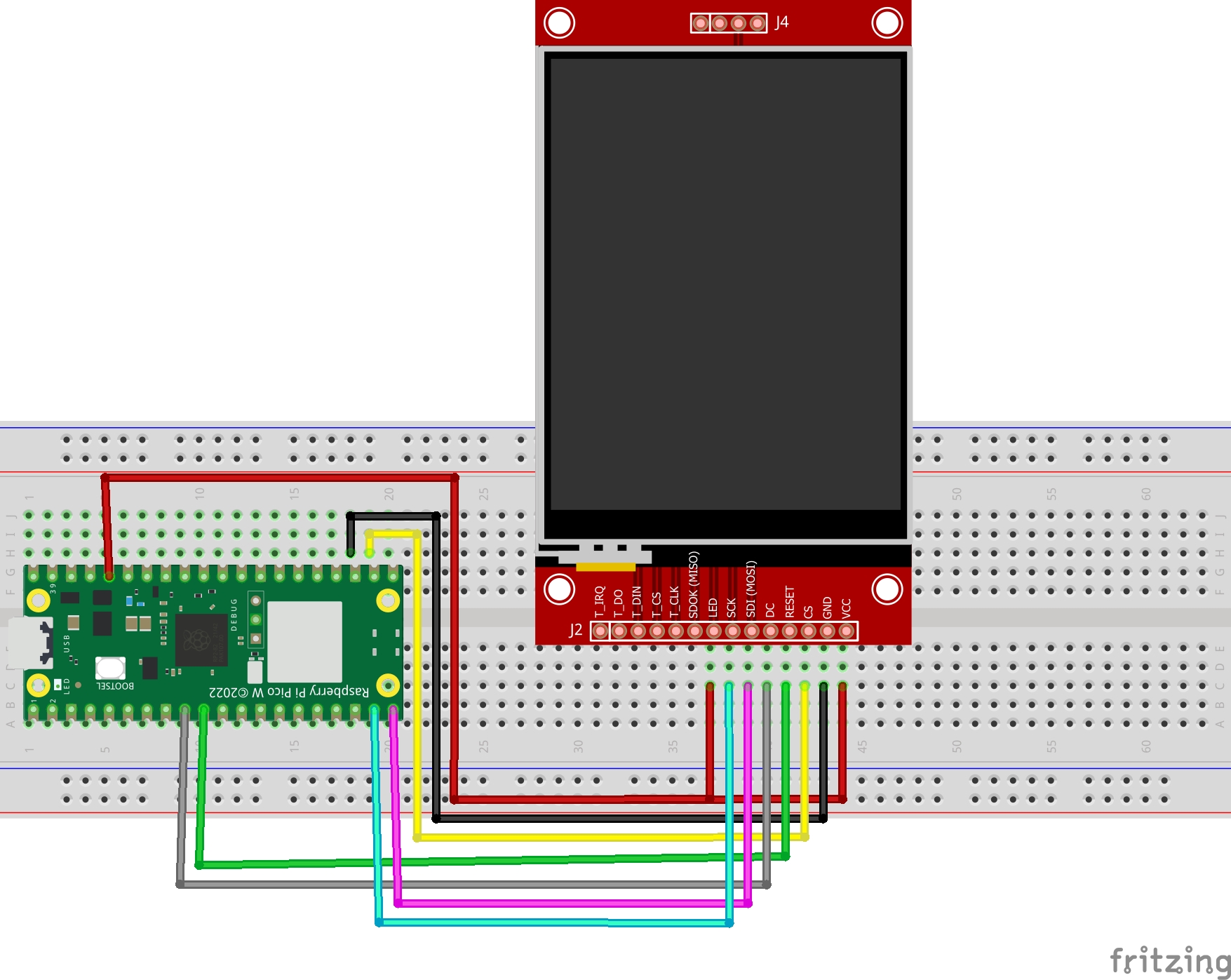
Later I also found another page that showed someone using a library already and having some issues, but that had a little schematic of how he connected the TFT display with their Xiao. I also found that super helpful in my designing.

Making the Schematic in Eagle
Regarding the schematic design I followed a little tutorial that I found in Spanish that helped me understand a bit how to connect some stuff and how to use the auto router in the PCB as well. Only thing with the tools the tutorial showed is that it was a 2 layers pcb, and mine is only one layer.
The changes that I made to my design where pretty straightforward. I basically added four modules for external connections.
-
One of them is an SPI connection that will allow me to connect my ili 9341 display and if needed some other SPI devices as well, this is prepared for that.
-
An i2c bus, ready for any components that will work using i2c communication, minor changes to the Fab Xiao where the positioning of the pins, for convenience when routing.
-
There are also two other modules, that will allow me to connect devices that need a 5V VCC, a connection to Ground and a Signal bus. There are four pairs like these in total that work like the All purpose pins that were in the Fab Xiao already, only that I added a Vcc bus as well (this was because I had the servos in my mind already).
I also left the LED and the button where they were to test the board if needed and also to test the LED as an output.
Here is how it ended up looking

> PCB DESIGN
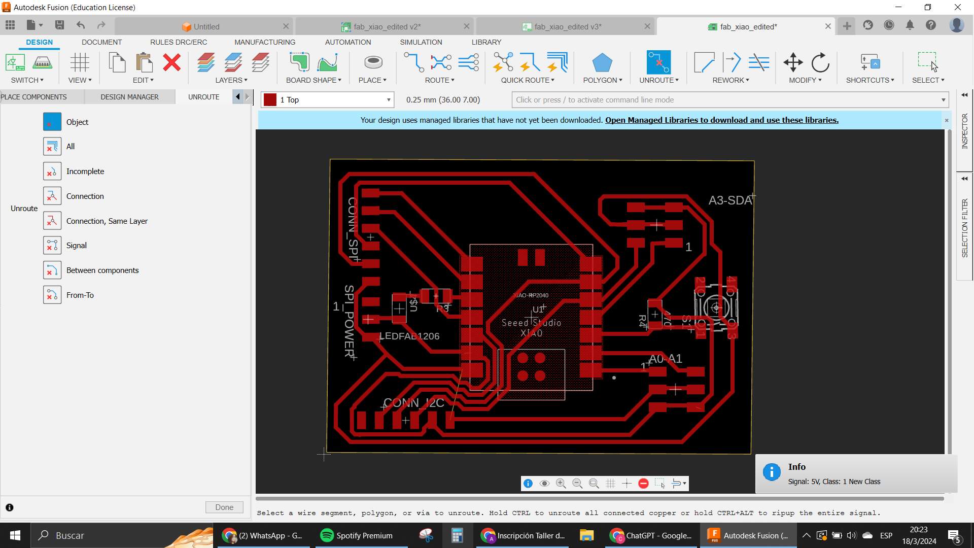
When I felt a little comfortable with my design in the schematic I went into the PCB part of Eagle to start seeing how to create the board in physical form. My first thought was to create a smaller board where all my components will fit and start putting them in places where I felt will be the closest to the pins they needed to be connected to.
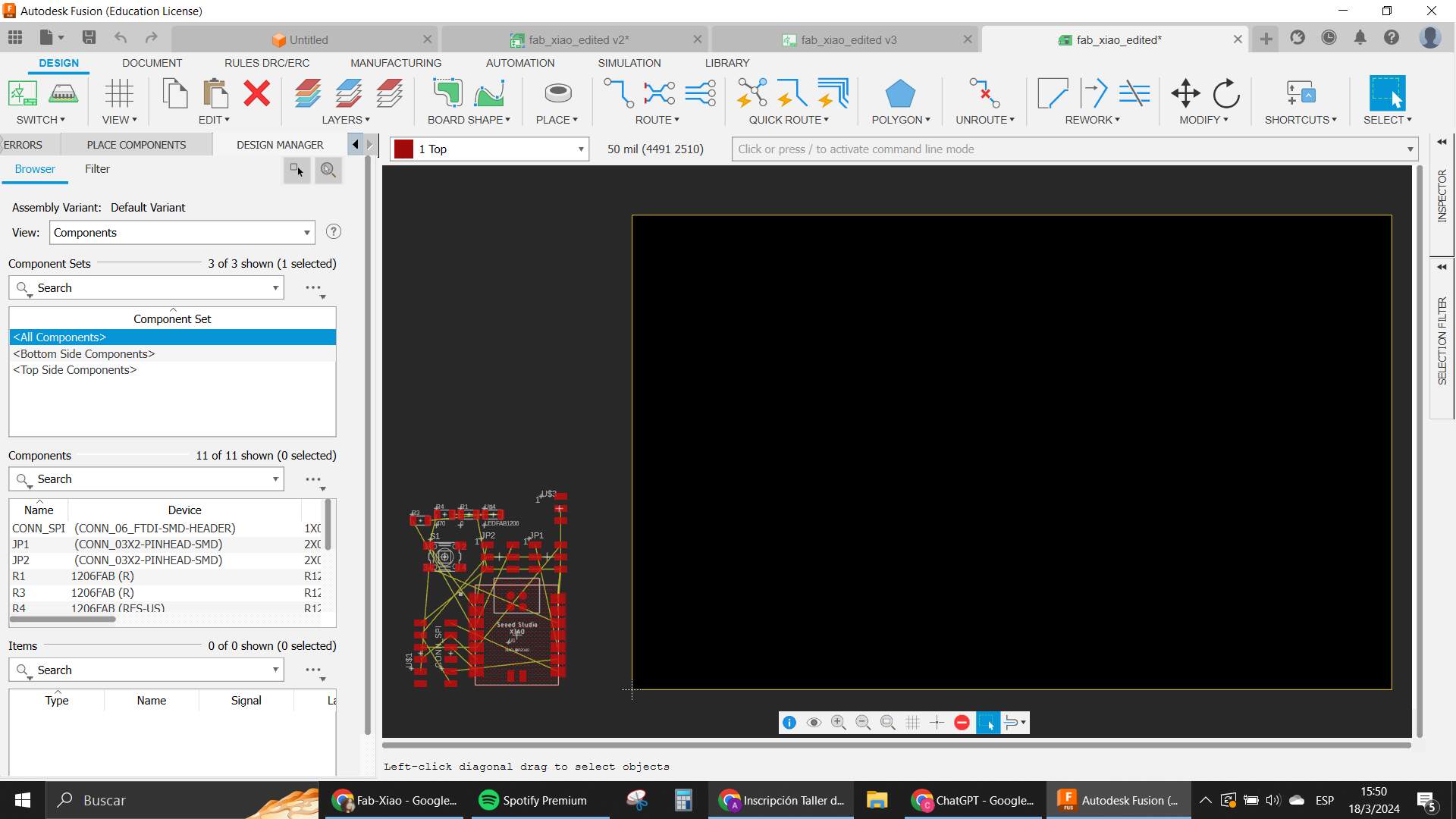
The yellow lines connected move according to where the closest connection is to that same signal or bus, so I tried to use that also to take into consideration where to put my components.
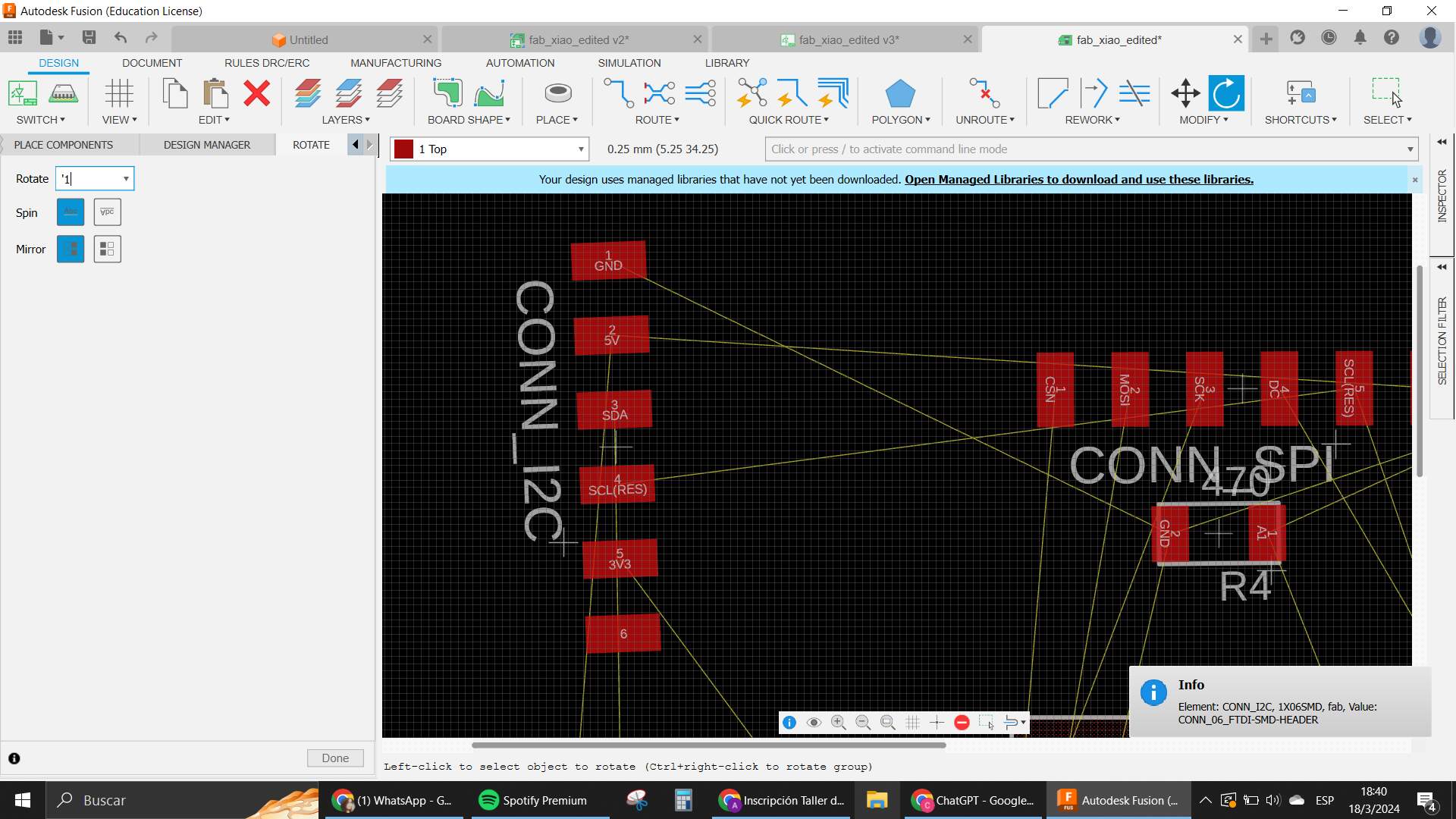
I started to test some of the ways to Route components like the manual and also the tools that Eagle has to make it more automated. Of course the manual way is a little messy and also very very complicated because you have to calculate all of the positioning by yourself. so I think the most efficient way of doing this is by mixing the Autoroute tool and some little manual tweaks here and there.
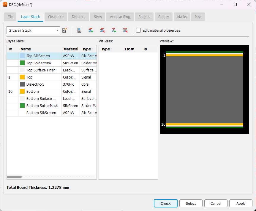
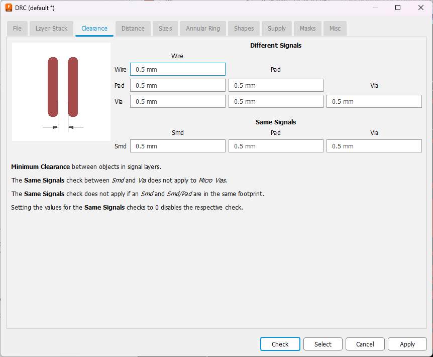
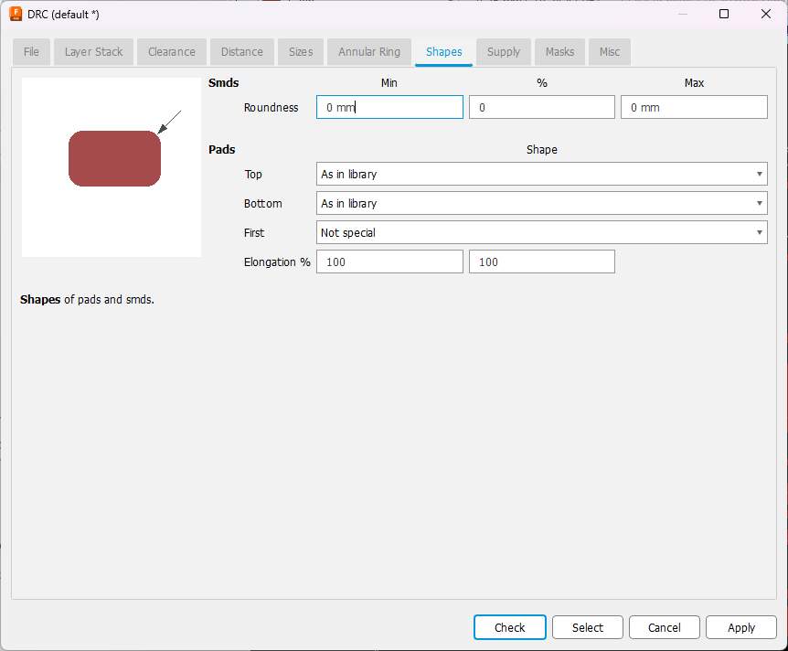
Before actually routing with the auto route I had to make some changes into the DRC ruleset so my design will be millable with our CNC machine. The most important thing I did was to make the tracks 0.5mm big otherwise they were too thin, and I went around that for everything else in my rulecheck. Here are the values.


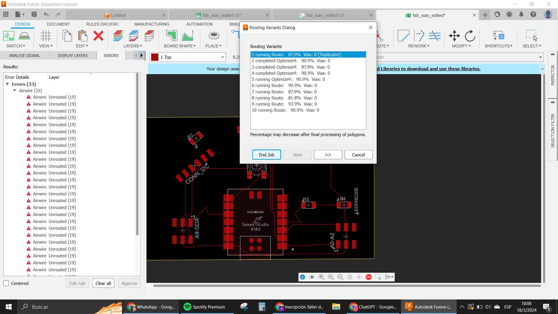
After having those ready, I moved and rotated the components around a lot. And the autoroute was used SO MANY TIMES! But I always ended up with something not connected. I tried to move things and so, but it was still a big challenge to leave everything where it needed to go.
To be honest, nothing seemed to work with this disposition. At one point, I had only one wire left to connect.
I gave up at that point and tried using a 0ohm resistor to finish up the circuit where the connection was. It was a 5V connection, so I put the resistor in the middle of two 5V nets to see if it helped. I also wanted to test “vias”, but I wasn't sure how to use them and couldn't change it in my DRC either (I mean I did, but it wasn't working like I needed it to). So I scrapped the idea and went in with the resistor as a way to make the connection.
Problems and Tribulations
This week was complicated because my time slot was very limited to work on the assignment. I had other appointments and plans, like one was to go to a concert that I was waiting for since last year. The plan was to have the board ready before this, but we had issues with a very horrendous heatwave on this particular week. I became sick because of the heat on Friday and Saturday, so I couldn't work that much.
Sunday we tried to work in the lab, since it rained the weather was more bearable. The only problem was that the electricity was out in the lab so we couldn't really work on what we needed to do.
Monday is when I made most of my advances and Tuesday was the concert I was talking about so I couldn't really work that day, but there were other things going on as well, cause the University had a strike going on too.
My plan was to finish on Wednesday after Neil's class (since I already presented I wasn't that worried about the deadline xdd). While the class was happening I started preparing my FlatCam project to take the job into the CNC. One of my classmates who also couldn't do the machining on Tuesday because of the strike went to the Modela first, we prepared the job together for him to use the CNC and then it was going to be my turn.
While he was working on that, I remembered that our Xiao's were used with a package in mind. When we prepared the Quentorres, we used the version that had the crossed connectors for the SMD. This first version of my board didn't really have that connector. I used the Xiao as if I was going to solder it into the board. I realized and decided not to make the process of CNC that day, but to try to change my design again to fit those connectors.
I couldn't find the connector in Eagle's libraries, also it was not available in the fab library. So I went back into the documentation for the Quentorres to see if I had any luck there.
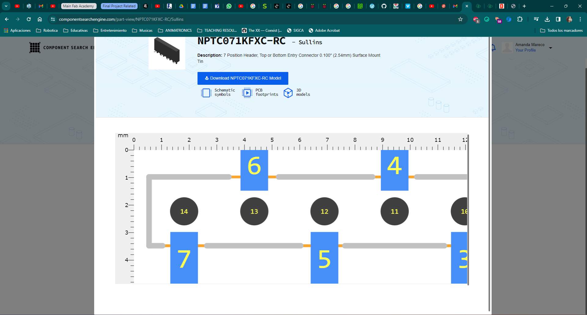
Well, the library wasn't there, but the name of the component was . This was enough to start looking into some libraries online to see if I could find it in there. Snap EDA was not a success, but Component Search Engine was. Here is the component from there.
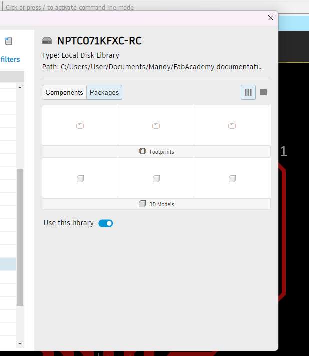
I downloaded the zip file and looked for the Eagle library (it has libraries for many different kinds of EDA tools). I unzipped it and went to follow the process already explained before.
To my surprise, the component only had the symbol, not the footprint, or 3D package as promised. It was a very disappointing moment for me cause I started to lose hope on how to make the Xiao package for my design.
I went back to investigate how to design my own footprints, since I had a reference in the component search engine page of sizes and distances. So I thought it could be a way to make it work for me.
I found some videos that helped me see how to replace components or change the footprints and create custom components too.
So with this information, I went into the library section of Eagle, opened the library where all the Xiao rp2040s were into and used one of those footprints as a reference, as well as crossing information with the component page in CSE, and seeing a little bit how it ended up looking in the version of the quentorres.

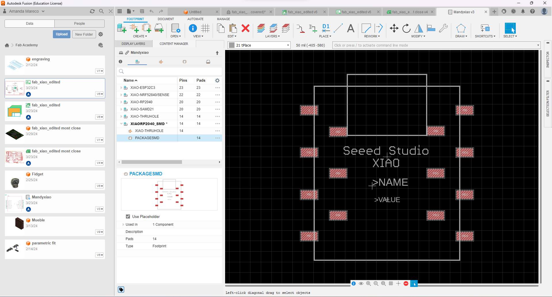
Using the grid of the PCB creation workspace of the library, I made the SMD component first (which was what I needed). Then I had to connect the pads to something. I then copied one of the XIAO's that had the pins equal to the amount of pads, and using the component creation tool, I connected the symbol to my footprint to create a Xiao Package component.

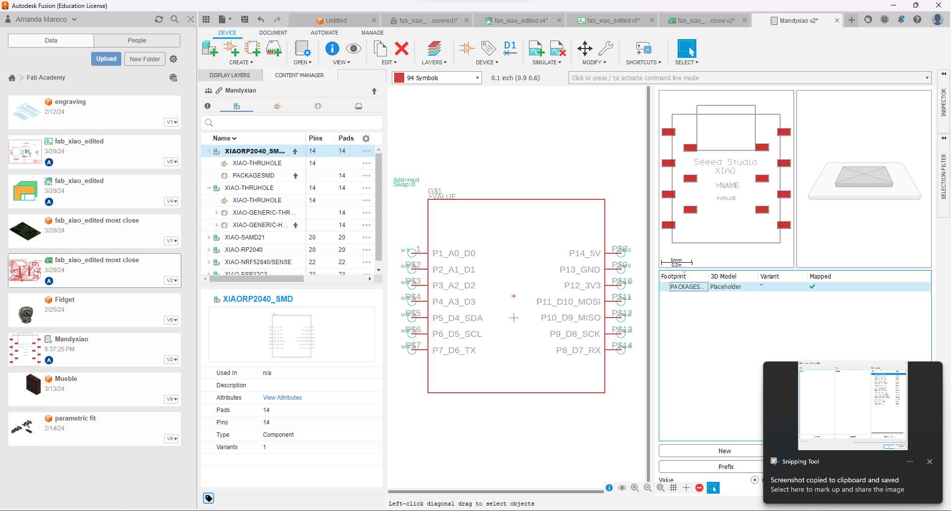
I saved the library and called it Mandy Xiao and started using it in my design. You can find that library in the download section on the side of this page.
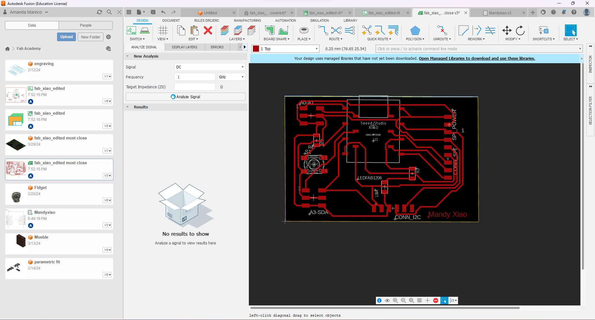
When the new manually created smd component was ready, I went into my schematic, and using the “replace” tool, I selected the new component that I just created. This made it easy because it already made all the connections seamlessly. The only thing left to do was to make the routing again so it could be ready with this new tracks.
After some attempts with the autoroute that left some connections unmatched, I made some changes into the position of the pins in my connectors for the i2c. Tried the autoroute, and lastly manually connected one last thing that was left out and TADA, the board was finally ready!
Now the problem was that from Thursday on, the lab had another power outage, but this time it was even worse because the problem was that one of the transformers connected to the line was malfunctioning. This was something completely out of our control, so we couldn't really use the lab for many many days. I truly panicked at this point and felt pretty upset. I was already quite behind on this assignment, and now this also made me have problems with the Output Devices assignment, since this board was going to be what I used to test everything.
Anyway, this problem continued for many days. While that happened I kept on trying to document things but to be completely honest, it was hard to keep advancing while having the despair of not knowing when we would be able to continue doing the machining that we needed for the board.
Saturday and Sunday were documentation days. Monday morning too a little bit. Finally the power supply was restored in the late afternoon so I went to start with the CNC and soldering.
Machining and Soldering
I prepared my job in the FlatCam software again as always. Using my documentation from the electronics production week came very handy. Thankfully I was very detailed in there cause I basically used that as a guide to make the preparation quite fast.
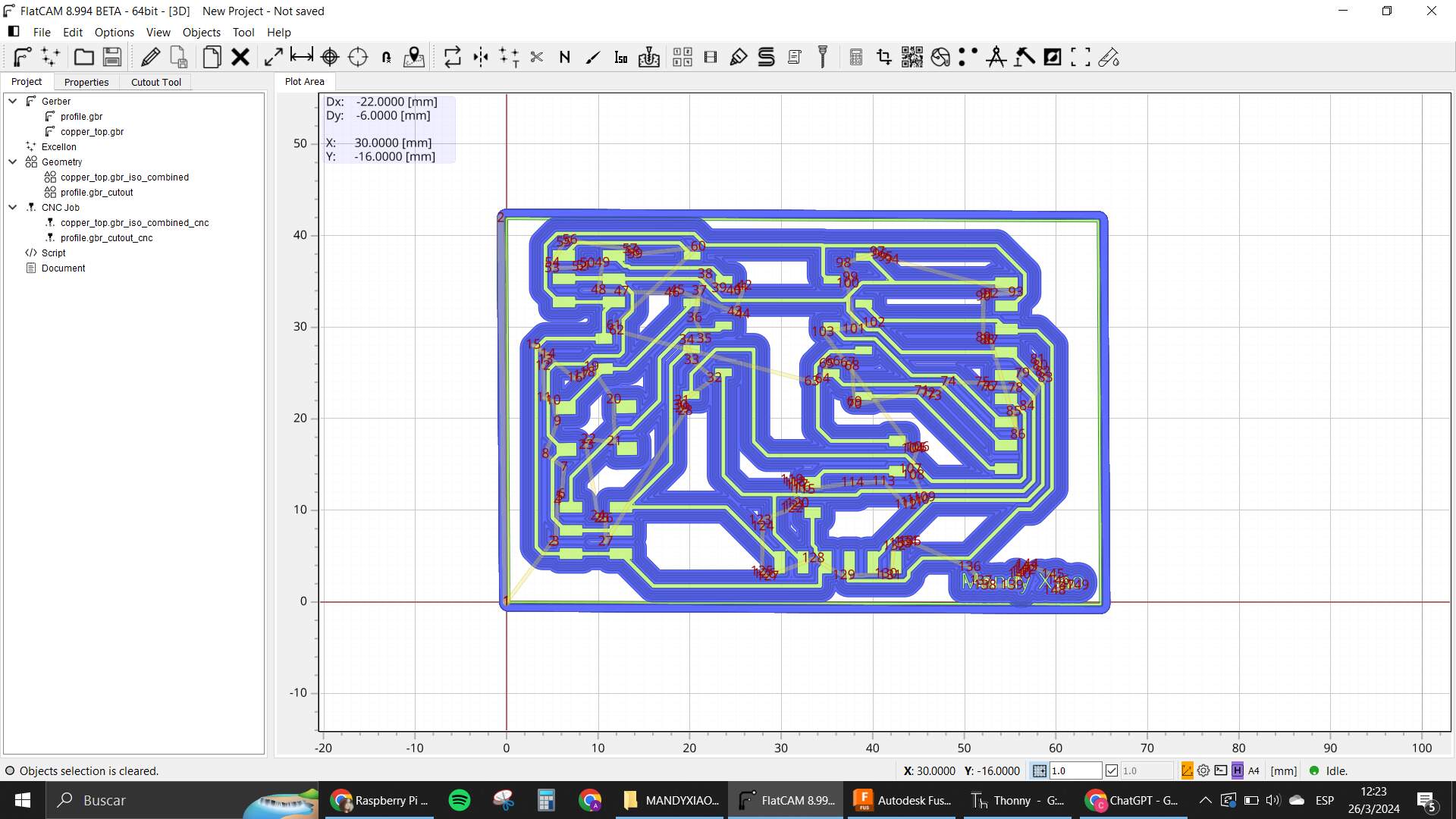
The machining though, was not smooth sailing, because the Z was not deep enough to make the isolation correctly at first. I had to change the origin at least 3 times for it to start actually working as I needed it to.
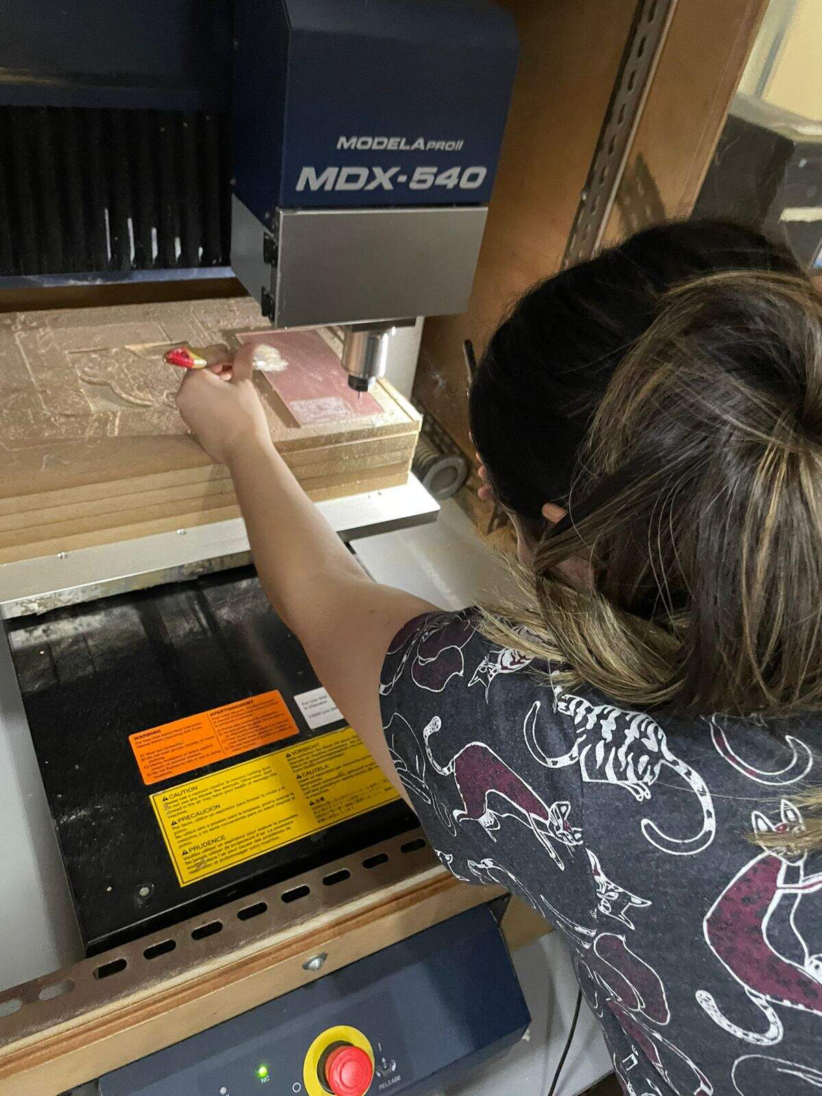
After that was finished. I started soldering. I found all the components I needed and began to do the arduous job of putting them in their place with a lot of care.
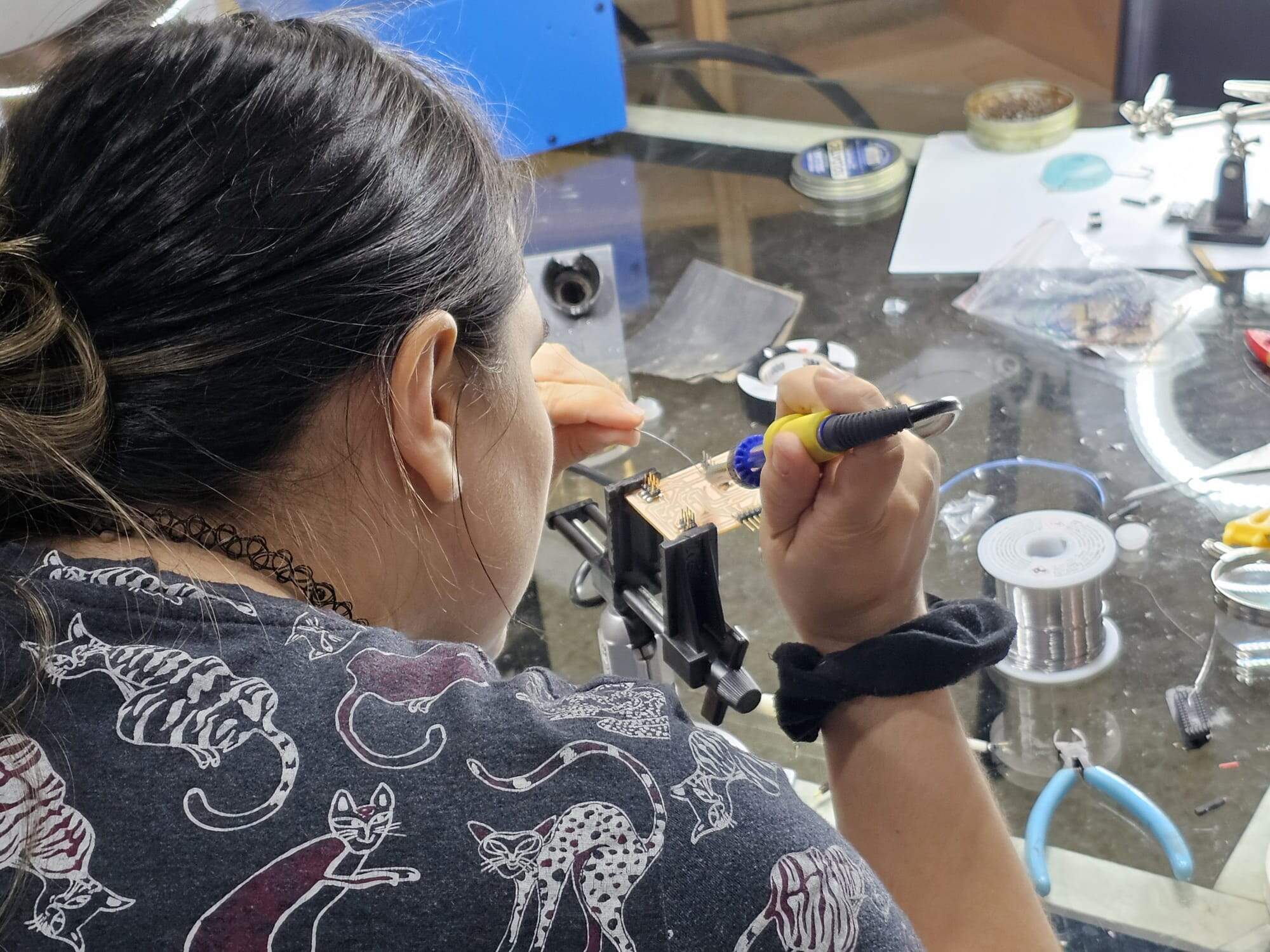
Finished with that now all that is left to do is test it with programming!! :D

> Programming
For the programming to test the board, I used a little blink program, to see if the LED was working as needed. Most of the other things that are included in my board will be tested in the Output and Input weeks.
I used a very simple program that I have used with the XIAO before in my Quentorres test. And it worked.
Here is a video of that.
Groupal Electronic Design
-
Use the test equipment in your lab to observe the operation of a microcontroller circuit board (as a minimum, you should demonstrate the use of a multimeter and oscilloscope)
Multimeter:
What is a multimeter
Which one do we have in the lab
Using the tester to measure voltage
Oscilloscope:
What is a oscilloscope
Which one do we have in the lab
Using it to view signals:
Multimeter
To start working with these types of tools we need to understand them better. I asked ChatGPT to tell me a bit about a Multimeter and here is what it said:
A multimeter is an electronic measuring instrument that combines several measurement functions in one unit. It is commonly used to measure voltage, current, and resistance. Here are the key features and functions of a typical multimeter:
Functions of a Multimeter
-
Voltage Measurement (Voltmeter):
-
Measures electrical potential difference between two points in a circuit.
-
Can measure both AC (Alternating Current) and DC (Direct Current) voltages.
-
-
Current Measurement (Ammeter):
-
Measures the flow of electric current in a circuit.
-
Can measure both AC and DC currents.
-
Requires the multimeter to be connected in series with the circuit.
-
-
Resistance Measurement (Ohmmeter):
-
Measures the resistance within an electrical component or circuit.
-
Useful for checking the continuity of wires and connections.
-
-
Additional Functions (depending on the model):
-
Continuity Test: Emits a sound if there is a low resistance path between the probes, indicating a continuous circuit.
-
Capacitance Measurement: Measures the capacitance of capacitors.
-
Frequency Measurement: Measures the frequency of an AC signal.
-
Temperature Measurement: Some multimeters come with a thermocouple to measure temperature.
-
Diode Test: Checks the forward voltage drop of diodes.
-
Parts of a Multimeter
-
Display: Shows the measurement readings.
-
Selection Dial: Allows you to choose the type of measurement and the range.
-
Probes: Two wires with metal tips used to connect the multimeter to the circuit or component being measured.
-
Red Probe: Typically connected to the positive terminal.
-
Black Probe: Typically connected to the common (COM) terminal.
-
-
Ports:
-
COM (Common) Port: The black probe is always connected here.
-
VΩmA Port: Used for measuring voltage, resistance, and small currents.
-
10A Port: Used for measuring high currents (up to 10A).
-
How to Use a Multimeter
-
Measuring Voltage:
-
Set the dial to the appropriate voltage setting (AC or DC).
-
Connect the probes to the circuit across the component or section where you want to measure the voltage.
-
-
Measuring Current:
-
Set the dial to the appropriate current setting.
-
Connect the multimeter in series with the circuit so the current flows through the multimeter.
-
-
Measuring Resistance:
-
Set the dial to the resistance (Ω) setting.
-
Connect the probes across the component you want to measure.
-
-
Continuity Test:
-
Set the dial to the continuity test setting.
-
Connect the probes across the path you want to test; if the path is continuous, the multimeter will emit a beep.
-
Safety Tips
-
Always start with the highest range if you are unsure of the measurement range.
-
Never touch the metal parts of the probes while measuring.
-
Disconnect power to the circuit before measuring resistance.
-
Ensure the multimeter is properly set up for the type of measurement you are performing to avoid damaging the device or the circuit.
Multimeters are versatile tools essential for anyone working with electronics, from hobbyists to professionals.
Multimeter from the Lab
According to this, we can start looking at the Multimeter we have in the lab and the parts it has:

Testing the multimeter
We used the Multimeter to test the voltage of one of our PCBs that has a LED. We turned it on and off with a little program and that is what we wanted to check how the voltage was behaving.
In the video you can see that we used the probes to put the red one where the pin of the LED connection started and the black one in a GND position, so with this we can have the value of that whole section. The voltage varies a bit and is notorious that it doesn’t really reach the 3.3V that the XIAO supposedly has as an output.
Oscilloscope
Functions of an Oscilloscope
After using the Multimeter, we went ahead and stared to use the Oscilloscope. Again, a brief explanation thanks to ChatGPT to understand the tool better first:
An oscilloscope is a specialized electronic test instrument that allows you to observe the changing signal voltages, usually as a two-dimensional plot of one or more signals as a function of time. Here's a detailed explanation:
-
Voltage Measurement:
-
Displays voltage changes over time.
-
Allows you to see the waveform of the signal.
-
-
Frequency and Period Measurement:
-
Measures the frequency of a periodic signal.
-
Displays the period of the waveform, which is the reciprocal of the frequency.
-
-
Amplitude Measurement:
-
Measures the peak-to-peak voltage, which is the difference between the maximum and minimum values of the signal.
-
-
Phase Measurement:
-
Compares the phase difference between two waveforms.
-
Useful for analyzing signal timing and synchronization.
-
-
Waveform Analysis:
-
Allows you to analyze the shape of the waveform, such as sine waves, square waves, and complex signals.
-
Useful for diagnosing and troubleshooting electronic circuits.
-
Parts of an Oscilloscope
-
Display:
-
Typically a screen (LCD or CRT) that shows the waveform.
-
Displays the X-axis (time) and Y-axis (voltage).
-
-
Vertical System:
-
Controls the vertical scale (volts per division).
-
Includes input channels for connecting probes.
-
-
Horizontal System:
-
Controls the horizontal scale (time per division).
-
Adjusts the time base of the signal display.
-
-
Trigger System:
-
Controls the starting point of the waveform display.
-
Allows you to stabilize a repeating signal by setting a trigger level and slope.
-
-
Probes:
-
Connect the oscilloscope to the circuit under test.
-
Typically come with a ground clip and a probe tip.
-
Probes may have a 1x or 10x attenuation setting.
-
How to Use an Oscilloscope
-
Connect the Probes:
-
Attach the probe's ground clip to a ground point in your circuit.
-
Connect the probe tip to the point where you want to measure the signal.
-
-
Set the Vertical Scale:
-
Adjust the volts per division setting to fit the amplitude of your signal on the screen.
-
-
Set the Horizontal Scale:
-
Adjust the time per division setting to display one or more cycles of your signal.
-
-
Adjust the Trigger:
-
Set the trigger level to stabilize the waveform display.
-
Choose the appropriate trigger mode (e.g., edge, pulse, video) based on your signal.
-
-
Analyze the Waveform:
-
Observe the waveform shape, amplitude, frequency, and any anomalies.
-
Use measurement tools provided by the oscilloscope (cursors, automatic measurements) to quantify signal parameters.
-
Types of Oscilloscopes
-
Analog Oscilloscopes:
-
Use a cathode-ray tube (CRT) to display waveforms.
-
Real-time display but limited in memory and advanced features.
-
-
Digital Storage Oscilloscopes (DSOs):
-
Use digital memory to capture and store waveforms.
-
Offer advanced features like waveform storage, complex triggering, and digital signal processing.
-
-
Mixed Signal Oscilloscopes (MSOs):
-
Combine analog and digital channels.
-
Allow simultaneous analysis of analog waveforms and digital signals (logic analysis).
-
Safety Tips
-
Always use appropriate probes rated for the voltage and frequency of the signal.
-
Ensure proper grounding to avoid electrical shocks and signal noise.
-
Be cautious when measuring high voltages or working with live circuits.
Oscilloscopes are essential tools for diagnosing, troubleshooting, and analyzing electronic circuits, making them invaluable for engineers, technicians, and hobbyists alike.
Oscilloscope from the Lab
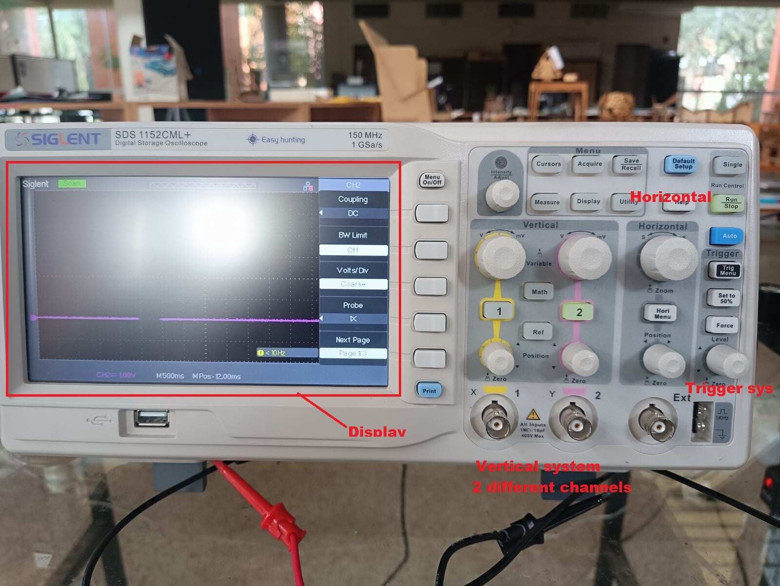
And again, let’s take a little look at the one we have in the lab with its parts:
Testing the oscilloscope
To test the Oscilloscope, we wanted to compare the values we got in the multimeter and see if we got something similar or not, we knew that the voltage was a DC voltage, and that it had a variation of pulses of 1s each, so basically for 2 seconds it was high, and 2 seconds it was low.
Here the video:
As you can see, we used the 500m/s division in the horizontal, and the 1V in the Vertical channel 2. In the Oscilloscope, the voltage was actually 3.3V, which was different from the multimeter, which leads us to believe that probably when it is an output like this one, the oscilloscope is better to have more precise readings.
Here you have the program we used: blink_groupal.py
And that was it for the week!