Week 4: Electronics Production
For this week's documentation we had to make and test a microcontroller development board.
The process for this was something I was a little used to since I have done Electronics before because of my major, but I had never really done it with a CNC machine so this was new for me.
Still, I had some health issues this week so I started working on Saturday which was not ideal.
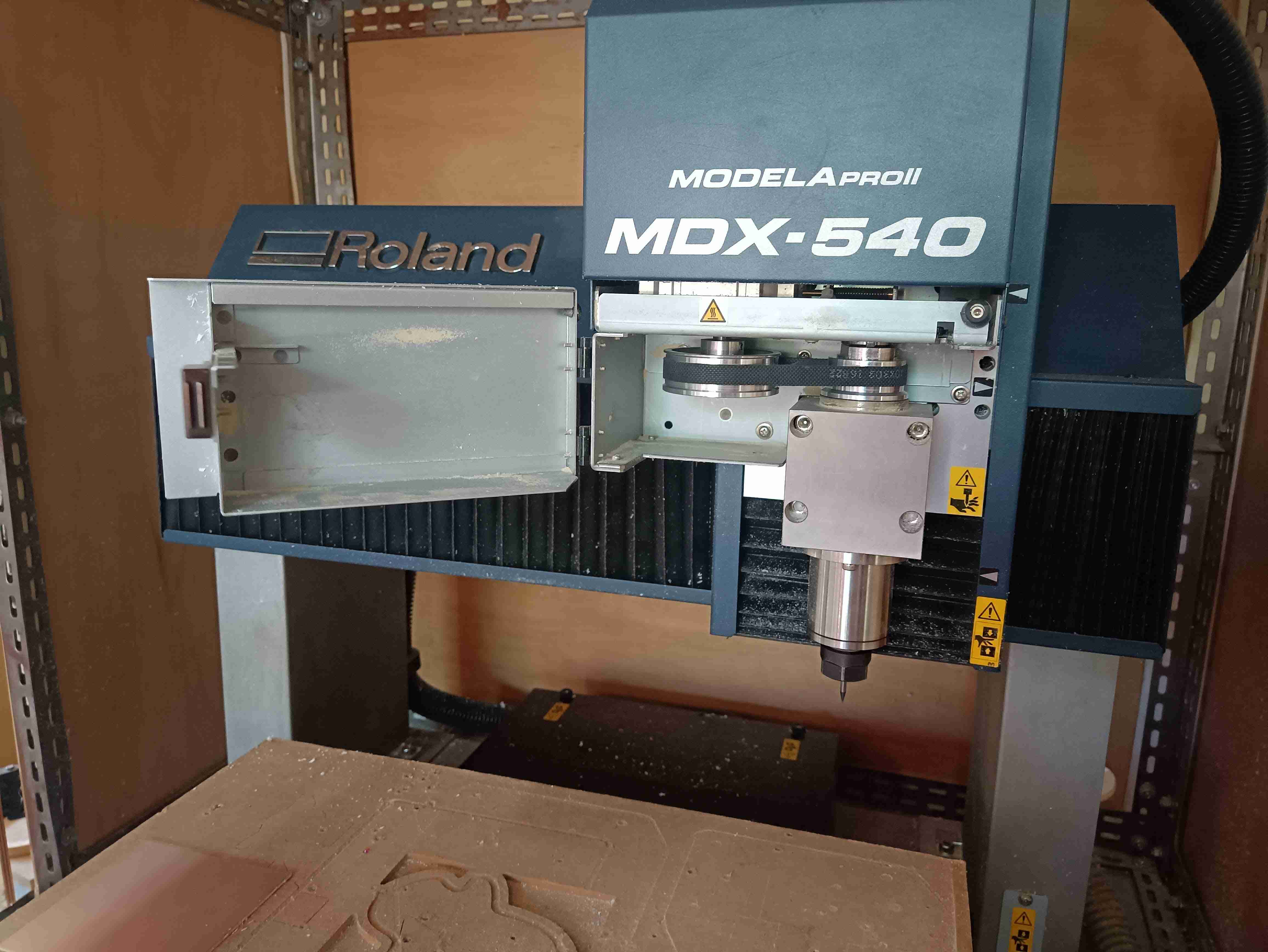
We had to learn how to use the CNC machine that is available in our lab, which basically is a MODELAPROII MDX-540, and the tools that we had for PCB Milling were some 1/64 in and 1/32in drills.
Group assignment:
- Characterize the design rules for your in-house PCB production process: document feeds, speeds, plunge rate, depth of cut (traces and outline) and tooling.
- Document the workflow for sending a PCB to a board house
- Document your work to the group work page and reflect on your individual page what you learned
Individual assignment:
- Make and test a microcontroller development board
Sections in page:
Creating the files for the Modela
The first step to do all of the process was to create the files that our machine can understand. In our case, we were advised to install a program that can create the .nc code that has all of the steps for the different types of work we were doing, and then our CNC understands. The name of this program is FlatCAM.
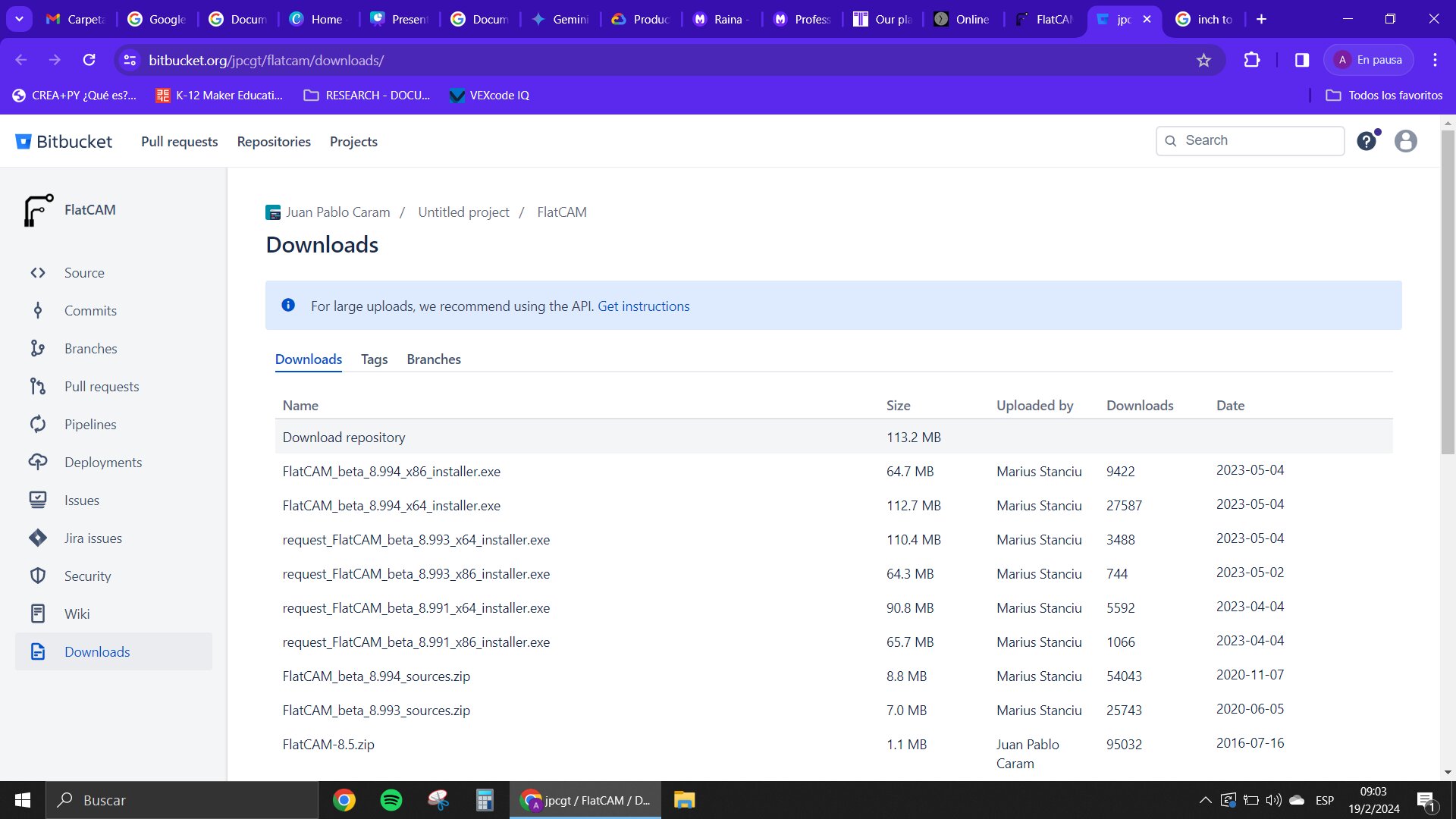
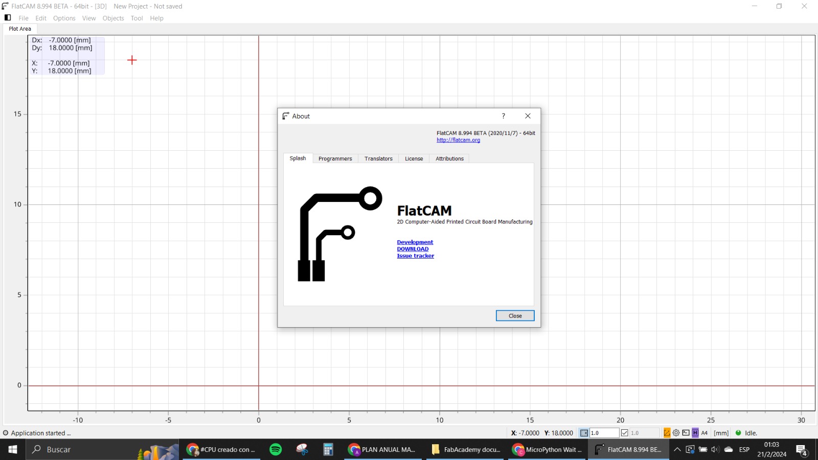
We had to download and install it on the computer and after that we had to do the testing with a test designed and after the test we knew all the parameters for our machine.
All of this is going to be in the group assignment page.
After having all of the tests done we started to work on the preparation of the design of the board that was required for this week's assignment in Adrian's repo.
We downloaded the repo and worked with the designs in gerber. I uploaded the front mask in Copper from the v2, and also the cutouts and the drilling holes.
The process for this was to open the gerber files and the drills actually are a different type of file that is named excellon that you need to upload differently.
Once you have all of the files uploaded you need to start working on the geometries for the work that you need the CNC to do.
Isolation
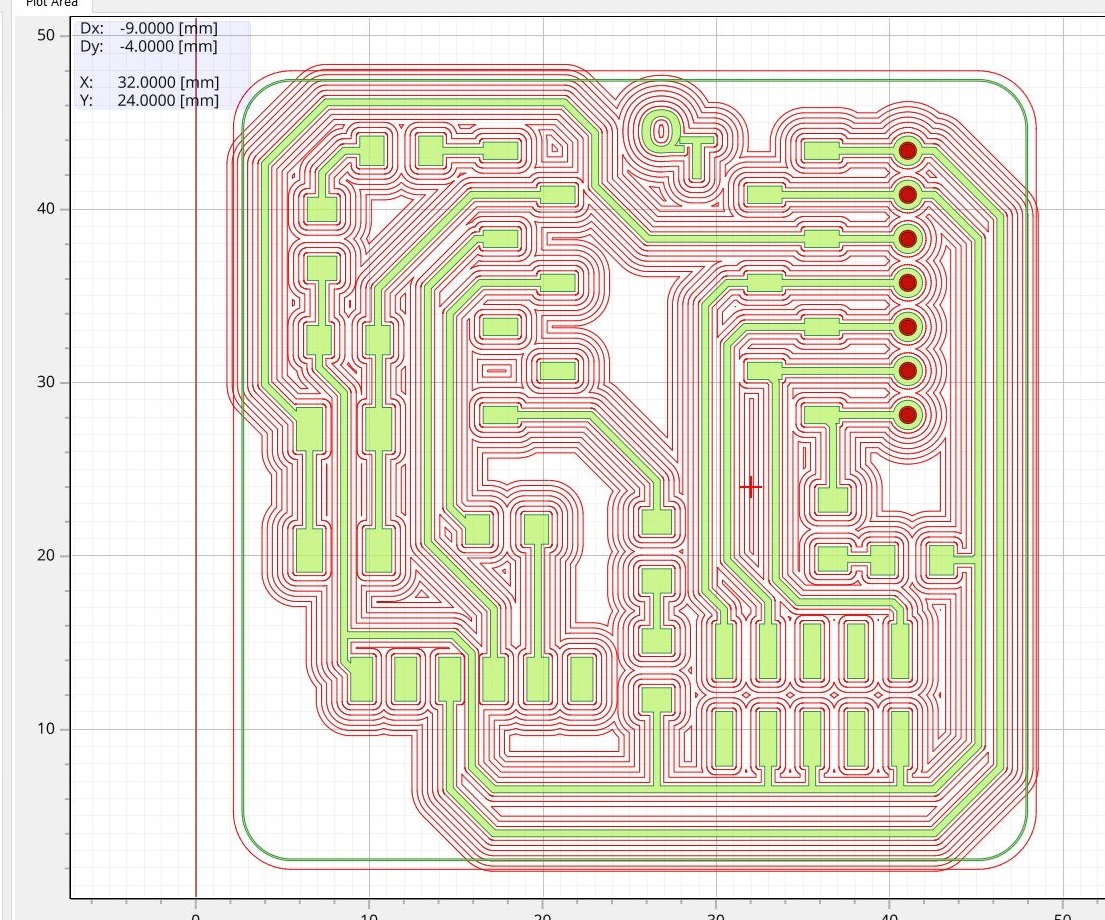
The first thing that we tried was to do the “isolation” for the paths of our PCB to be the only things on the board and taking out everything that we don't really need of copper on top.
This was done using the isolation tool in flat cam for the parts of the circuit that we had uploaded in the program.
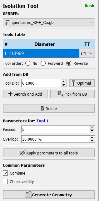
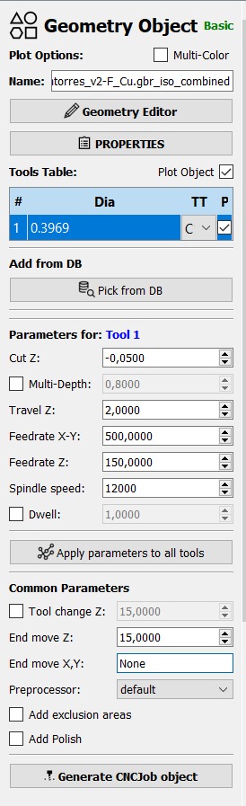
The isolation tool diameter and type it's going to be necessary for you to create the geometry, also the amount of passes that you want it to have: this is going to create traces surrounding all of the Gerber that you have selected and is going to make the same thing as many times as you put passes on. The other parameter is the overlap, which is basically the percentage that you want the tool to go over again in the previous path, at the same time that it is moving to do the next section/the next pass. We tested our design with six passes and an overlap of 30%. We also used the 1/64 in drill for this operation which has a diameter of approx 0,4mm. Here is a picture of how those parameters looked in our final design:
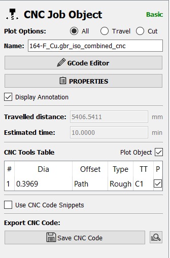
When you have the parameters ready you need to generate the geometry which is going to appear in another section of the projects in Flat Cam. Now when you go into the properties of this geometry, you have to look into the parameters that prepare the machine for the CNC process. Here you basically determine the speeds of the processes and how you want the machine to act when the processes are done. You can modify the speeds of all of the coordinates and how the collet is going to move around for example the speed rate in XY which is basically how fast the quality is going to move in those directions and also how deep the Z coordinate is going to be. You can also specify the spindle rate which is the RPM of the drill.
Having all of those set it up you can now generate the CNC process and save that into your computer as an .nc file.
Cutouts
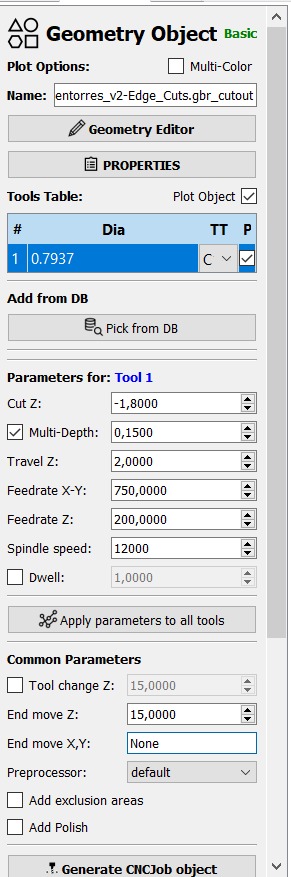
The second process was regarding the cutouts which are done with the cutout tool in flat cam. Here you have to select the geometry or the Gerber file that you want your cutout to be performed in and you also have to specify the diameter of the tool which in our case was 1/32 in.
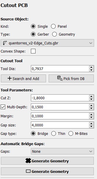
Also you need to specify how much you want to cut in Z which is the depth of the cut in our case we selected that or drill will go down 1.8 mm. There is also a multi-depth tool which you have to select and put the step in which your drill needs to go inside the element in each step. There's also the margin which is how the cut will be performed in the PCB if you put a positive value there the cut out is going to be on the outside of your selected geometry. In the automatic bridge gaps we select none so the whole PCB is cut out without leaving any bridge gaps behind. When you're done, you generate geometry and you also have to specify the parameters for the selected geometry as we did with the isolation.
When you have all of those values ready you generate the CNC job and you save it into your computer.
Drilling
In my first two tries I used the drills that appear in the PCB. In my final one I didn't really create the holes because they seemed unnecessary for what we needed but still here is how the process goes.
First, you need to upload the excellon file into the flat cam project. When you go into the properties of these you have to go and change the diameter of the tool specified with the “excellon editor”. We used the 1/32 in tool for this as well because it goes through the PCB.
You also need to put the parameters for the tool by clicking on the drilling tool. Here is a picture of those parameters used in my first tries.
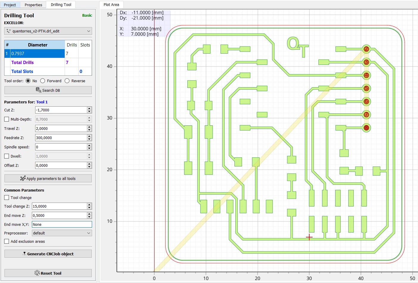
You finish with all of that, generate the CNC job and save it as well.
CNC Workflow
When you have all these ready you need to upload them into a USB and take them into the computer where you have the CNC machine setup.
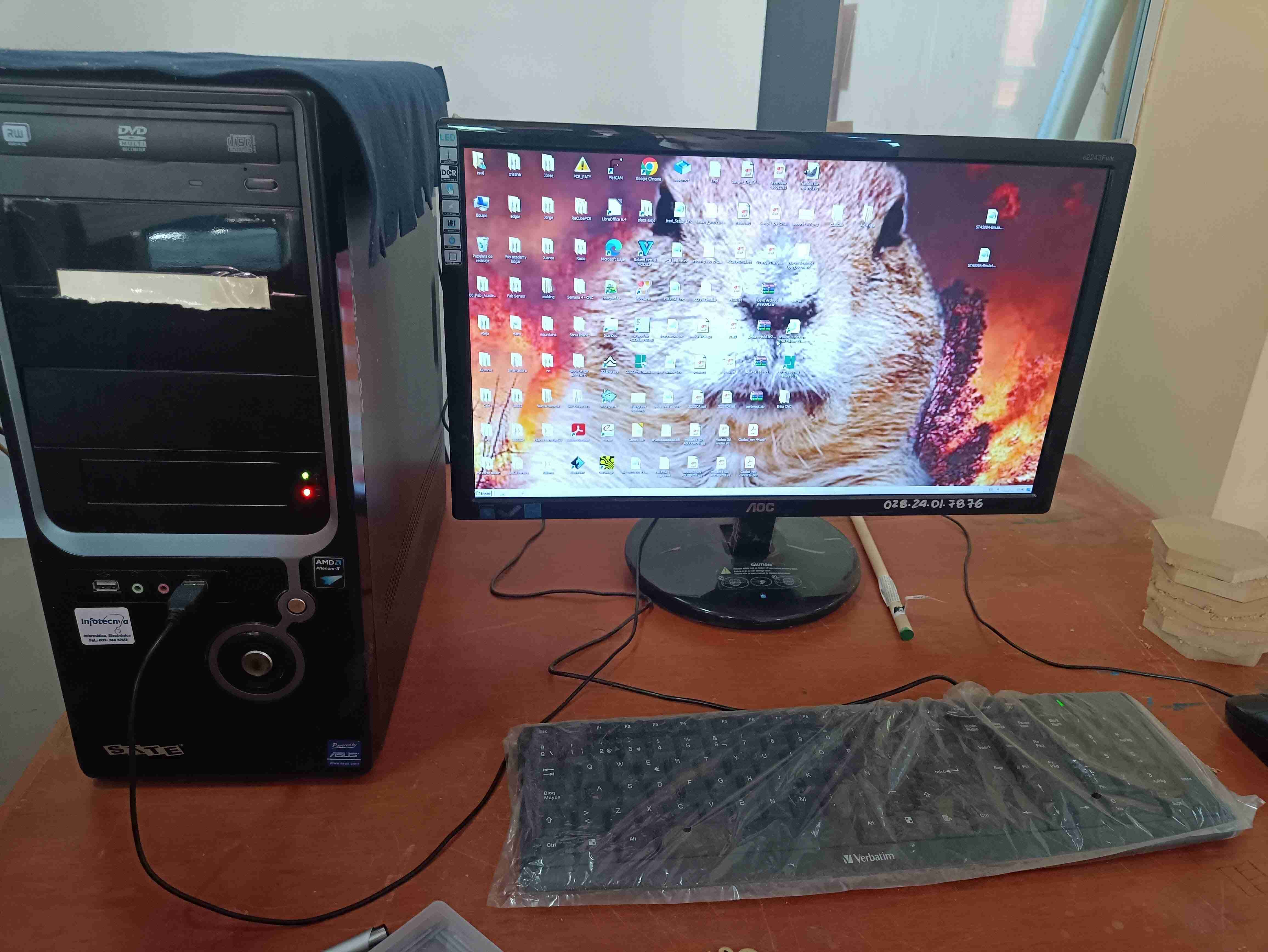
The first thing you need to do is turn the machine on because if you don't, the software that you use for this machine doesn't really open.
When you turn it on you need to press enter in the machine and you can start using the software.
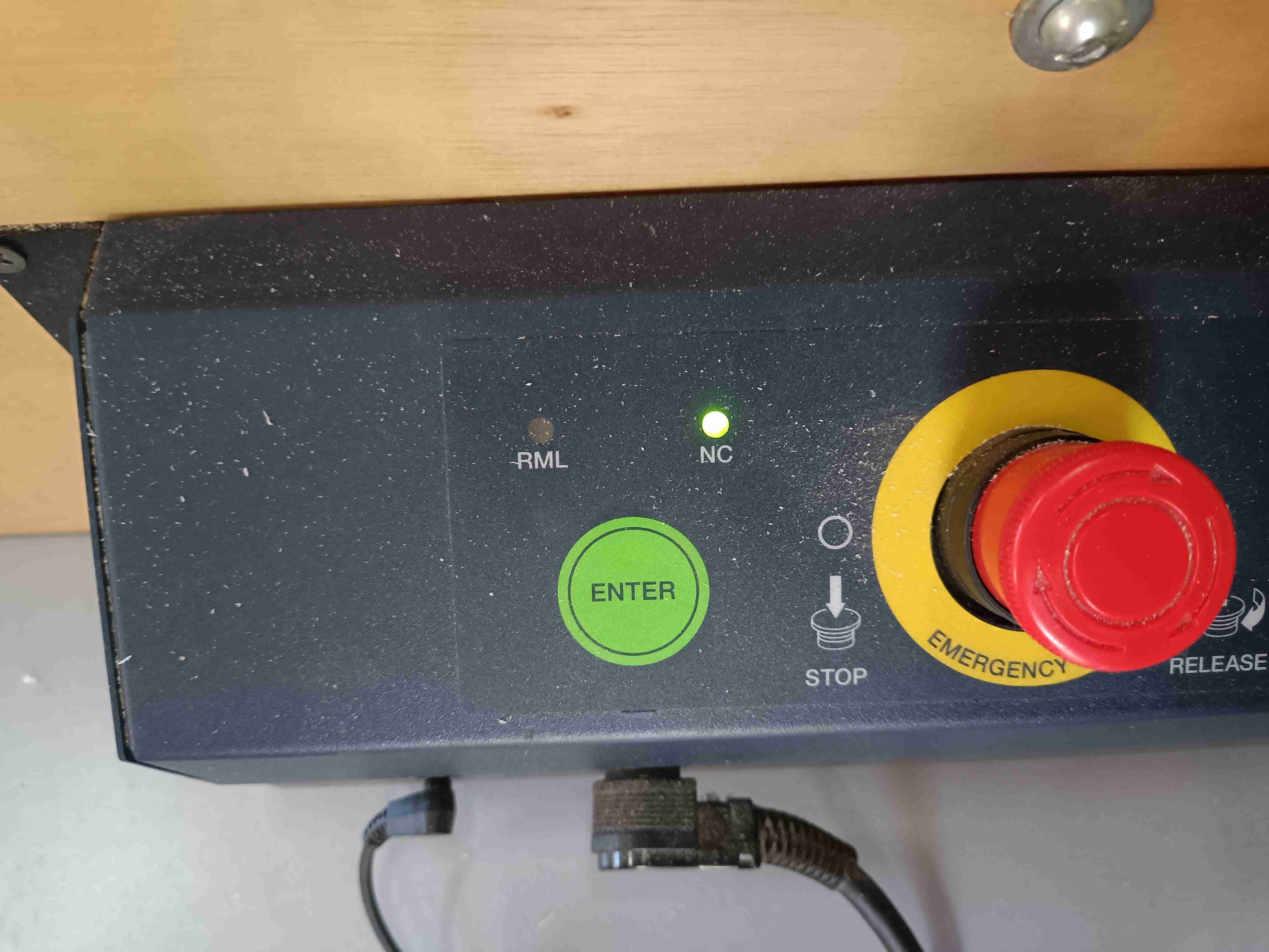
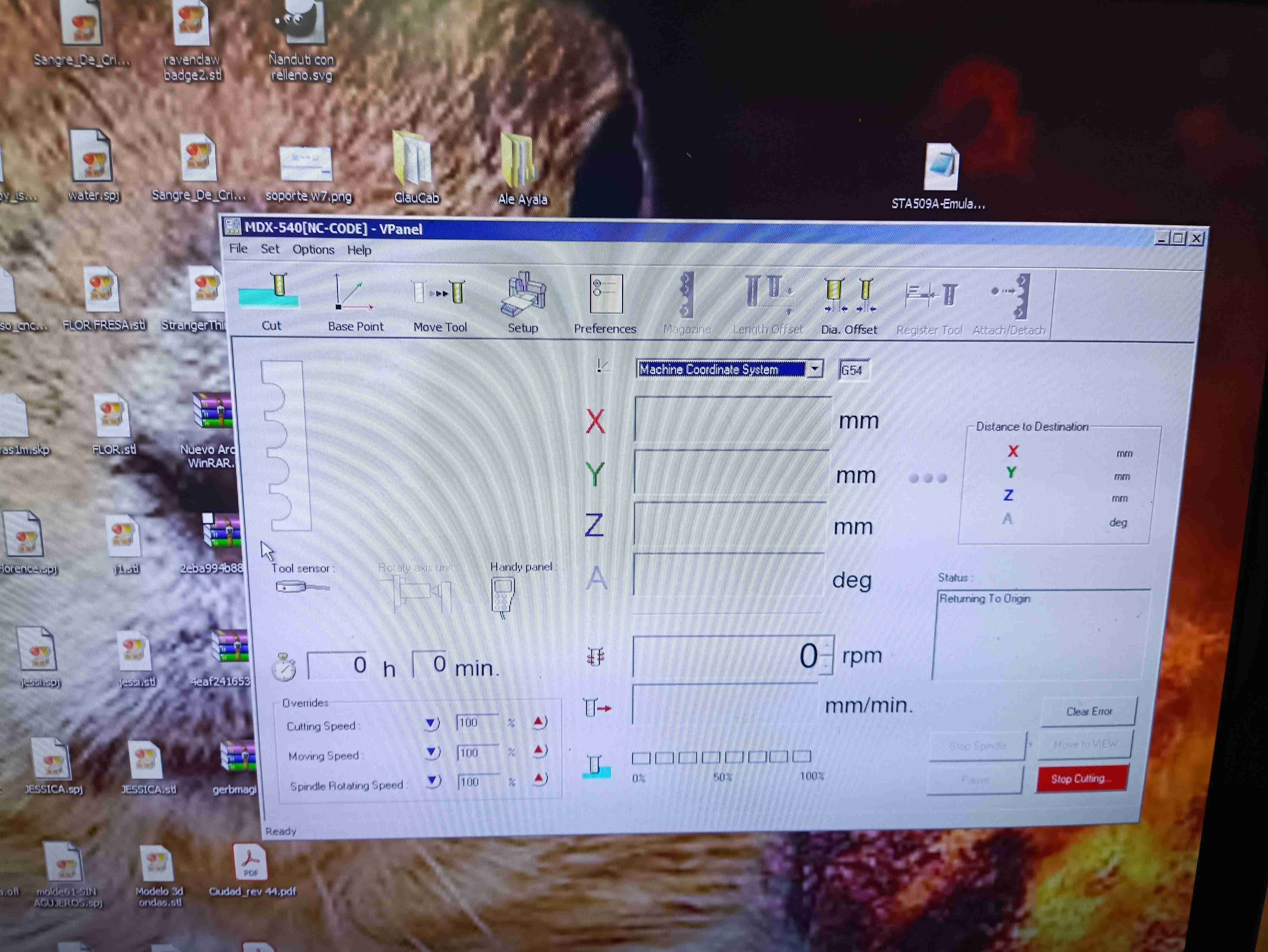
The software is called Vpanel.
Now regarding how to prepare the machine in order to cut a PCB board here are some steps that you need to follow:
- You need to put Double-sided tape throughout the whole back of the board so it can be attached to the sacrificing mat.
- Find a place in the sacrificing math that is as level as possible.
- Place the Virgin board on top of the sacrificing mat paying attention at the borders and making sure it doesn't feel loose.
- Regarding the tool that you're going to use you need to open the collet so you can access the places to change the drills.
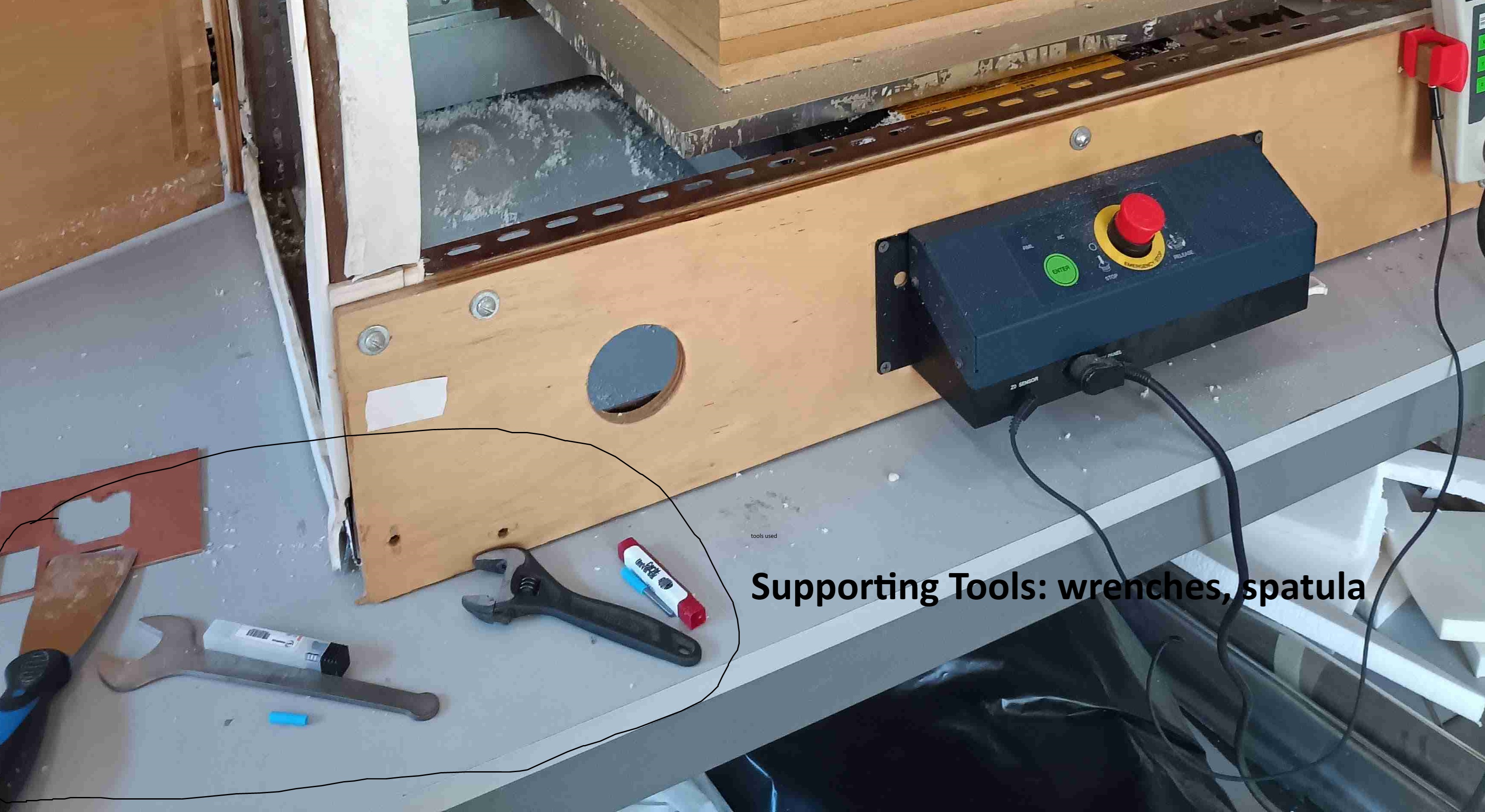
- Using some wrenches You let loose the collet and place the specific tool that you need for each job that you are going to do. In our case the 1/64 in for the isolation and the 1/32 in for the cutouts and drills.
- Once you have your board and tool ready you need to create a new origin, and for this, you use the control that is on the side of the modela or even the V panel software to try and place the X and Y coordinates in the bottom left corner of your design.
- Is very important to place it in a way that allows the machine to have a place where it actually touches the board as well ( in the case of this specific type of job and because of how the design was handled in flat cam)
- When you have the X and Y where you need them you set them as a user created coordinate system and set the origins with the control. Here is a little video of that.
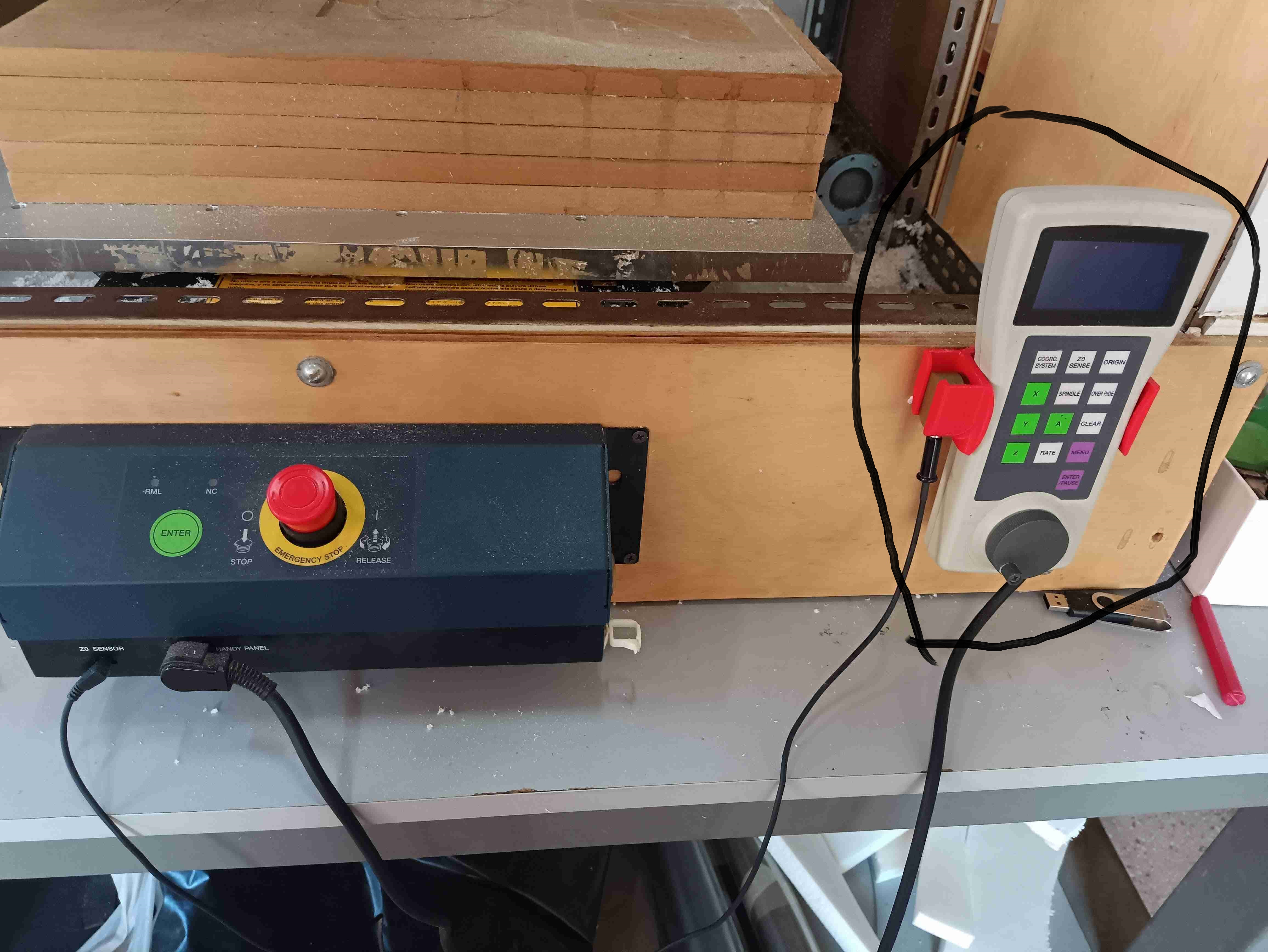
- After that you have to set up your Z coordinates and origin. For this we use a sensor that allows us to have a very precise feel of where the top of the board is. It is very important that only the tip of the drill touches the board and this is very hard to do by eye. That is why it's nice to have a sensor that allows us to do this.
- To use the sensor you need to place it on top of the board and put your spindle on top of the sensor giving it a little space between the drill and the sensor and using the tool inside the V panel called “detection”, Inside the base point section.
- Having all of these ready you now go into the “Cut” section of the V panel to upload your CNC file into the machine.
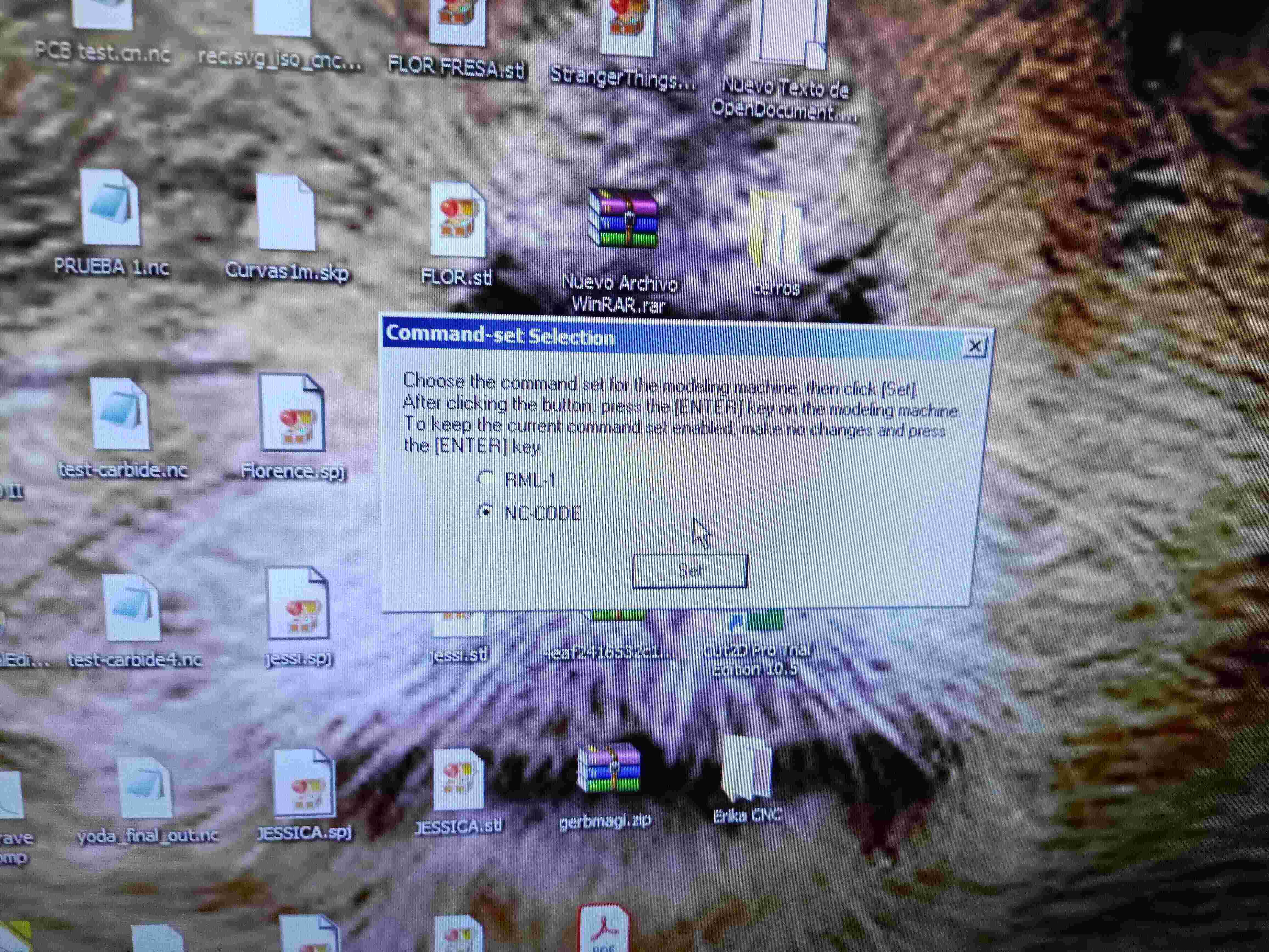
- A little point that we had to do before uploading our CNC files from Flat cam was editing the CNC code and taking one command called: M6 out, because this command basically didn't allow the machine to work properly, we did that by opening the .NC file in the notepad app and just deleting that part of the code.
- When you upload the file you have to apply the changes and see the output in the panel.
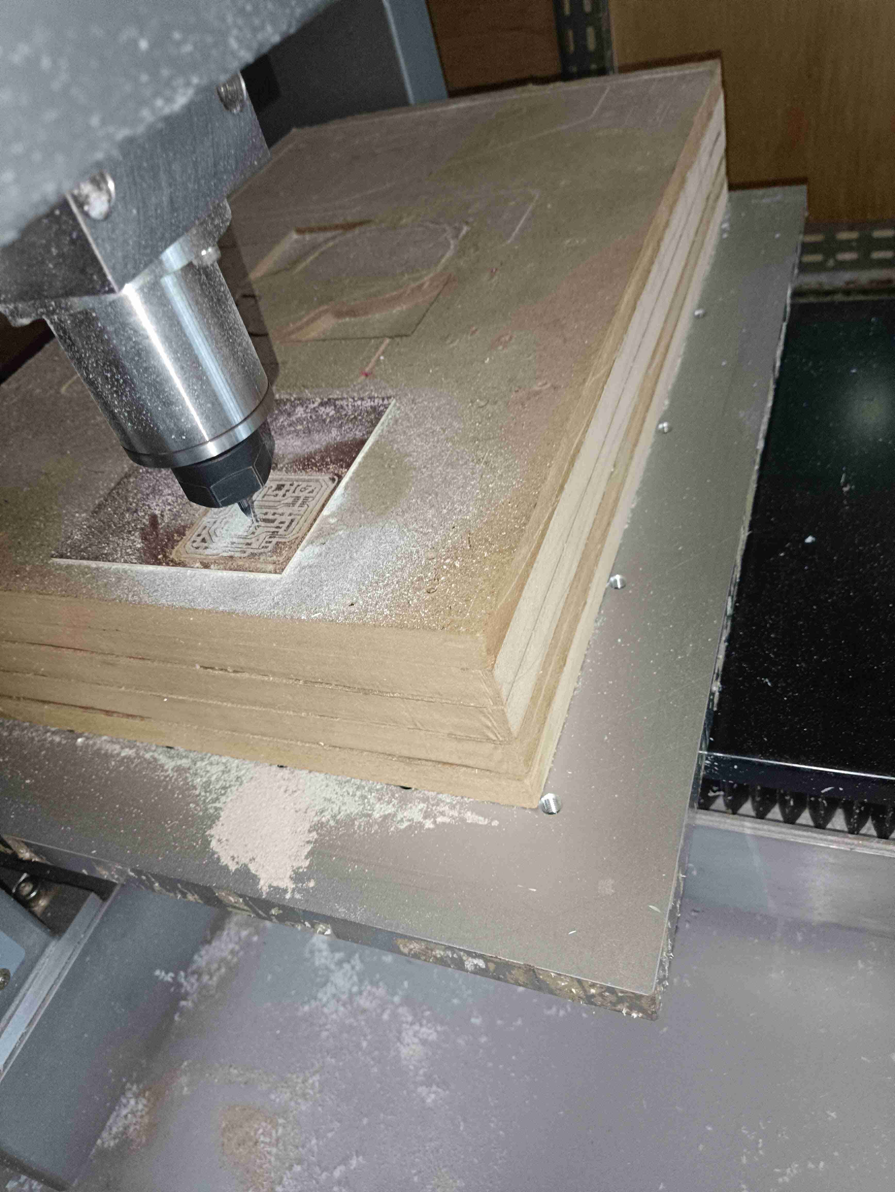
- When you put output your drill goes on top of the origin that you set up earlier.
- Having all of these ready you can press the resume which starts the process.
Obs: It's very important to keep an eye on the process at all times just in case the CNC is not really doing what you need it to do. What can happen is that your board is not leveled enough and some parts of your design are not really being cut as you need them and others are.
The solution that we found to these problems is to pause the process, then stop it completely and change the origin of the coordinate system by creating a new zero for the Z Coordinate. This means grabbing the handheld tool and pressing the origin button in the place where it currently is. This helps us a lot because basically we are moving our Z into a zero by 0.05 steps each time since that is the cut depth that we gave to our isolation tool.
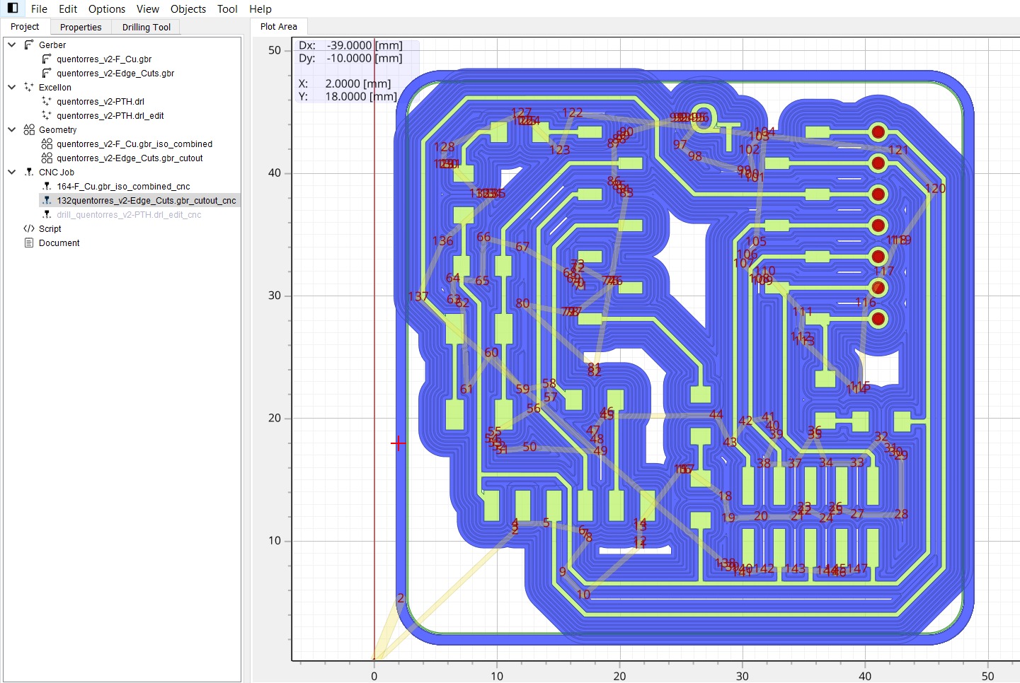
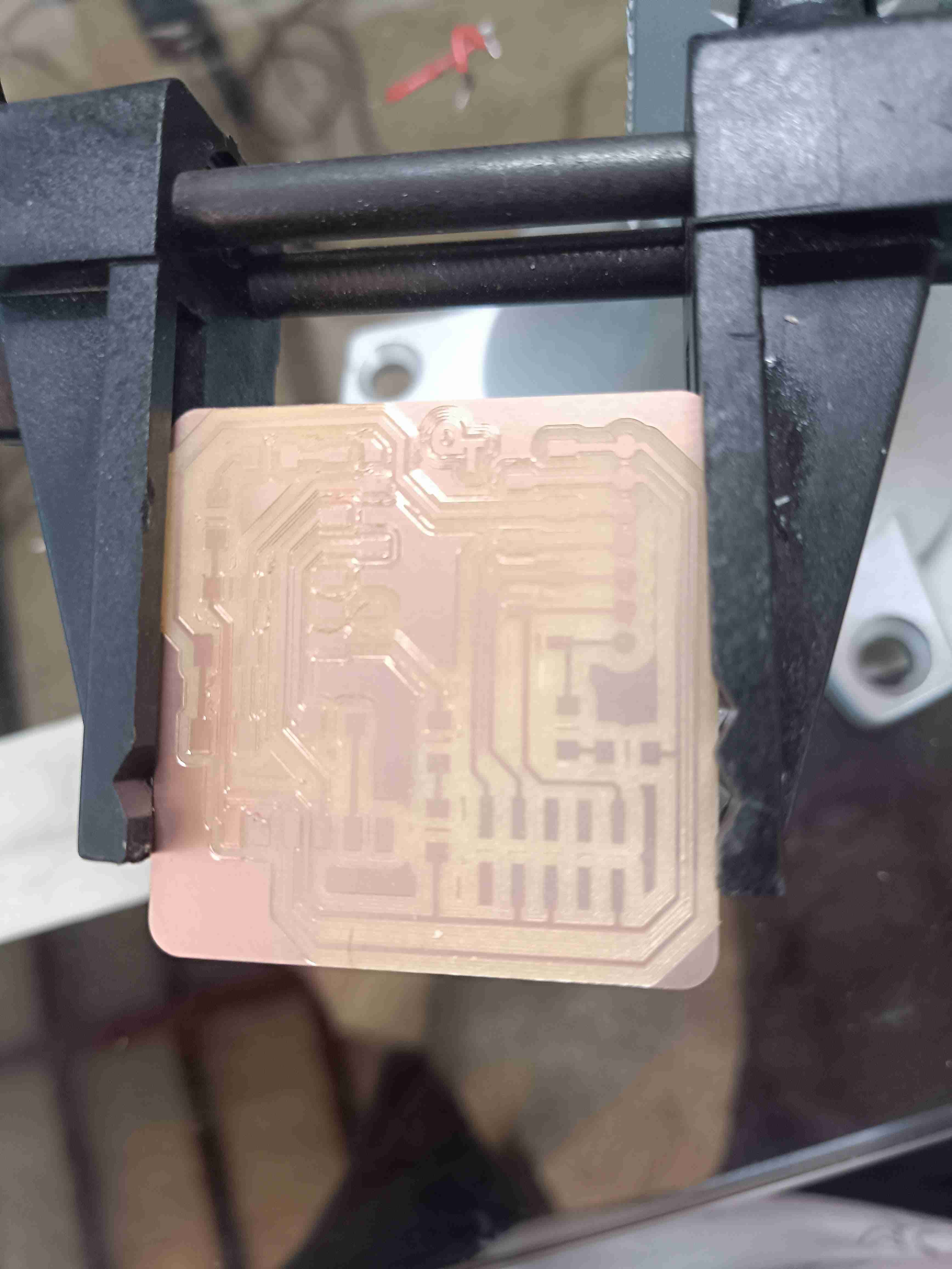
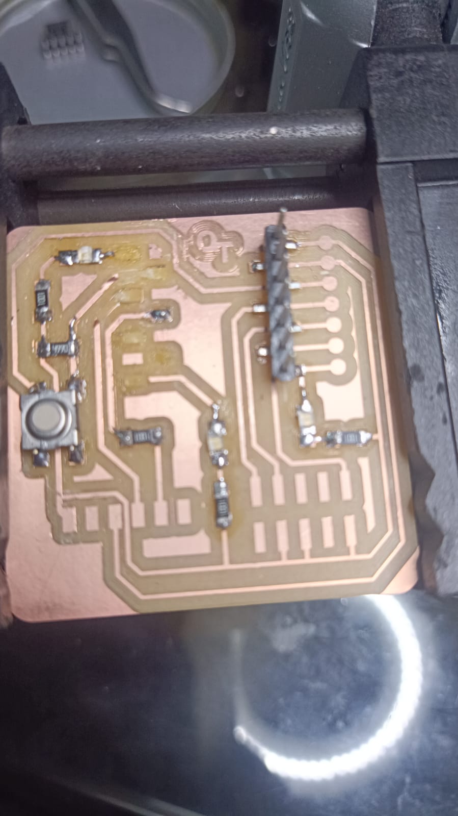
Here is a video of the process of the CNC cutting the PCB board and also some pictures of us working.
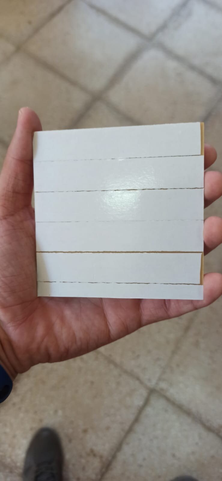
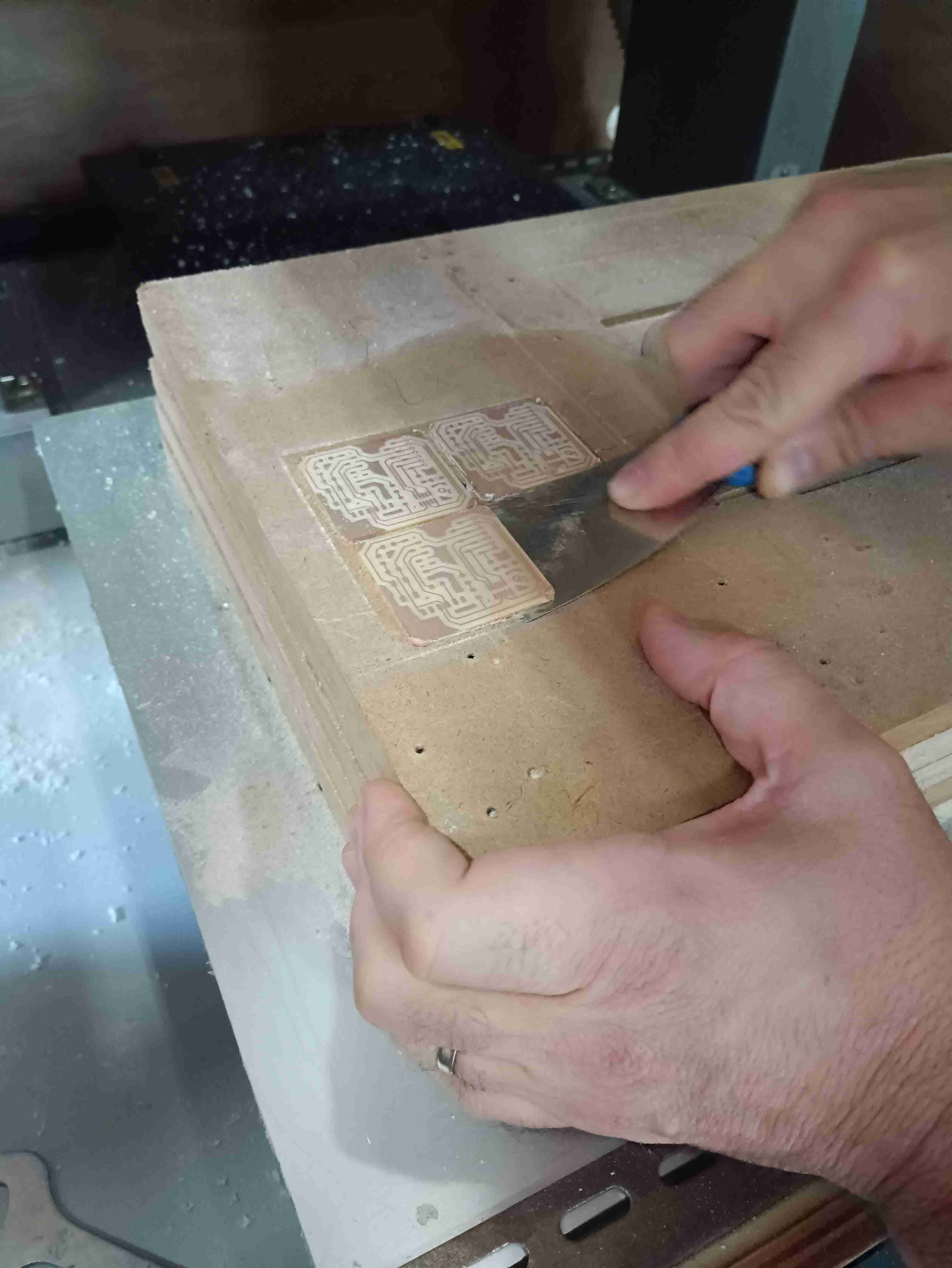
We decided to make the most of our virgin PCB by placing all of the designs into only one board.
Tips and reflections:
Something to notice is that if you put too many steps into the isolation and also the overlap is too low the process is going to take a lot of time, and when I say a lot, I mean A LOT O.O.
One of the processes of the isolation actually took 50 minutes to complete. With the right speed and spindle rate and also the right parameters for the geometry the process can be done in 11 minutes.
Also, when designing and editing in FlatCam, the design needs to be in the positive XY side of the coordinate system, near the origin is even better
The cut out was done in approximately 5 to 10 minutes depending on the speeds. It’s fast if you put the multi-depth in a number that the tool can handle, in our case that was 0,15.
When the collet is open, the machine won't move, make sure that each time you change your tool, you close the door.
It's very important to do the processes in order, you first need to do all the isolations, drillings, and you only do the cut of the board last, because the pcb can rise because of the speed of the cnc.
DO NOT BLOW INTO THE PCB WHEN THE CNC IS WORKING
When using the double sided tape, try not to overlay the tape, this is going to create a bump in your pcb and make problems to the cnc
Another thing to take into account is to be very mindful when changing the tools. Try to put the caps on top of the drills before handling the collet so the tips are not damaged if they fall.
One last thing to take into consideration is the process of taking out the board from the sacrificial mat, first, use the "move to view" button in Vpanel, to bring the mat in a good place, also being mindful that it doesn't break when using the spatula for it to come out is quite important and also cleaning the double-sided tape after the whole process is over.
Soldering
When you have your board ready the first thing to do is to clean the little parts of the copper where you don't need it that the machine couldn't get into for X and Y reasons. It's basically like weaving but with an exacto knife and a little more dangerous.
What you basically want to do is separate as much as possible the paths from each other if you end up with a little line in between them so they reduce your chances of making a short.
After you finish cleaning that up you put a coat of PCB cleaning product which leaves the copper layer as smooth as possible for the solder to be put on top of.
We used the normal soldering tools which I was a little used to using already because of my major and having made circuits in the past. We used the normal soldering iron and soldering tin.
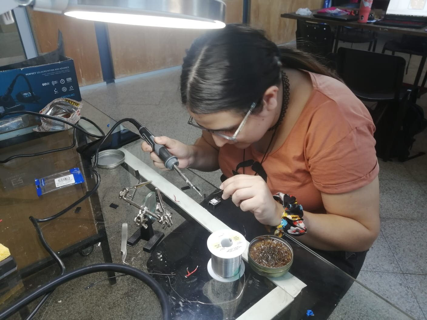
The soldering iron that we have in the lab is able to control the temperature, which is very important when working with electronics and especially when you work with SMD components, which is the case in this specific exercise.
The first time we tried and tested this we realized that one of the components was too big for the board that we had processed so we had to change the design again. In my case this was not that bad because my first tries with the soldering iron were not that great.
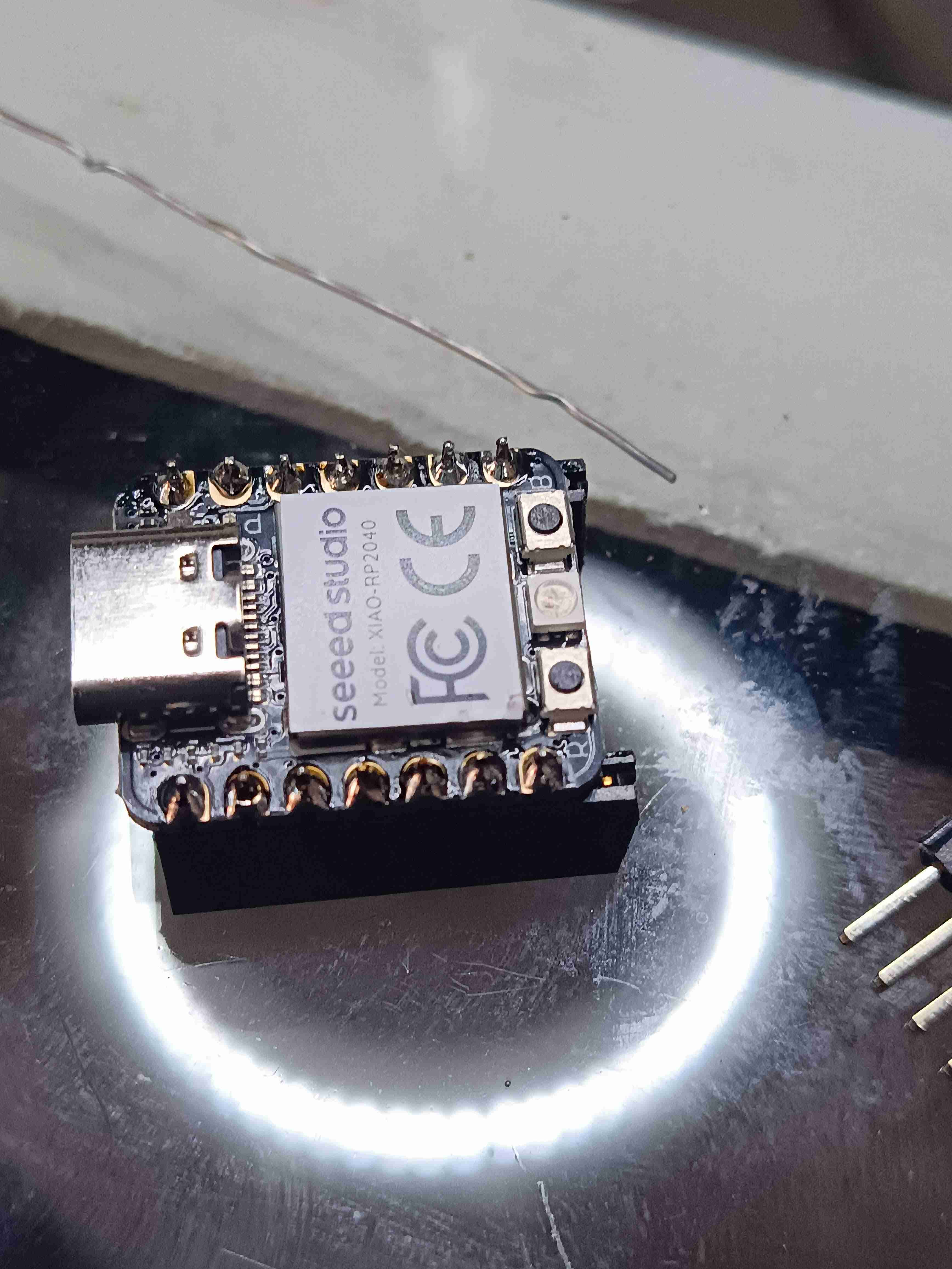
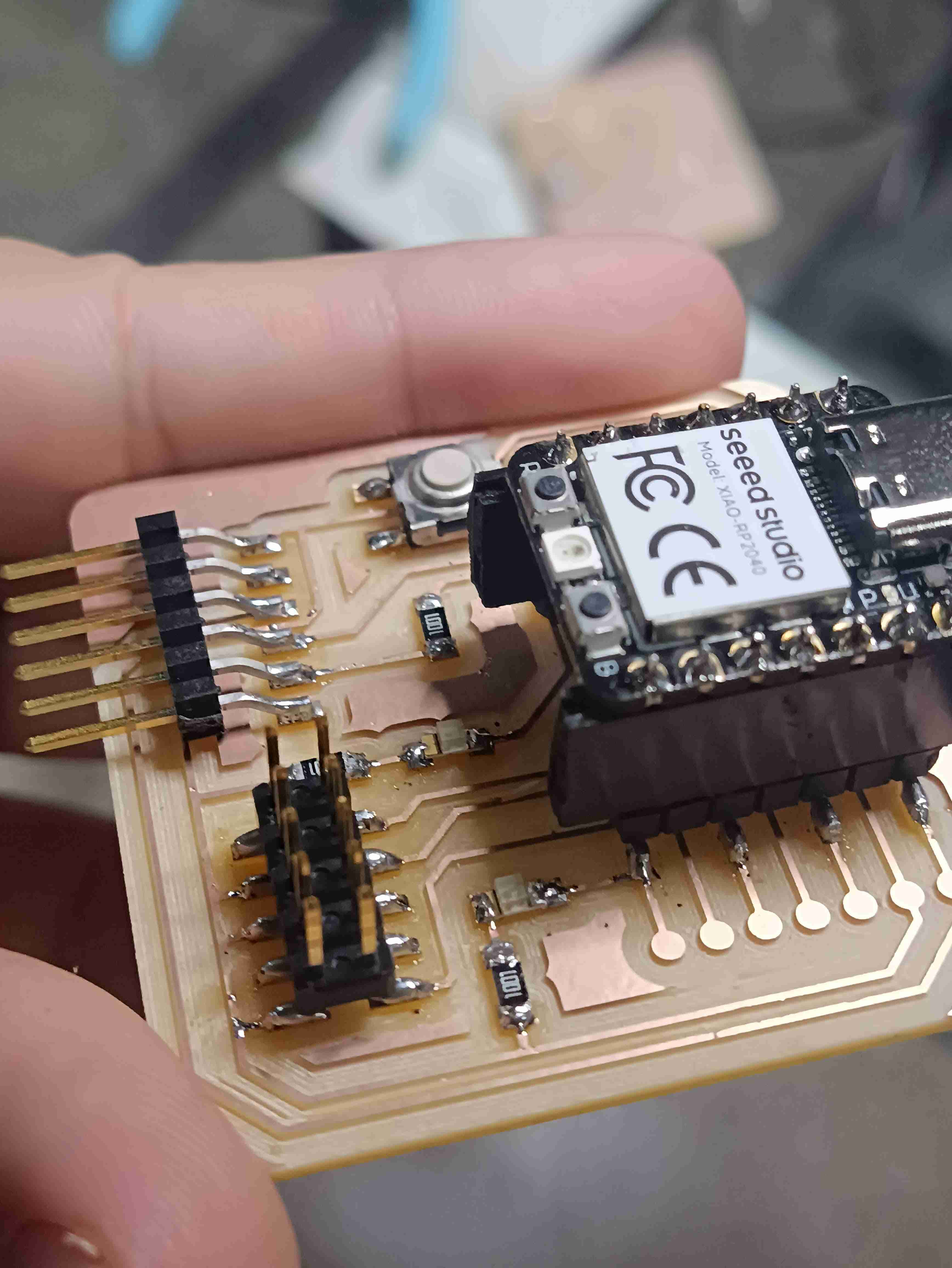
With my xiao microcontroller soldering was not as hard because it has holes and the components can go through them making the soldering easier, so I did that pretty fast.
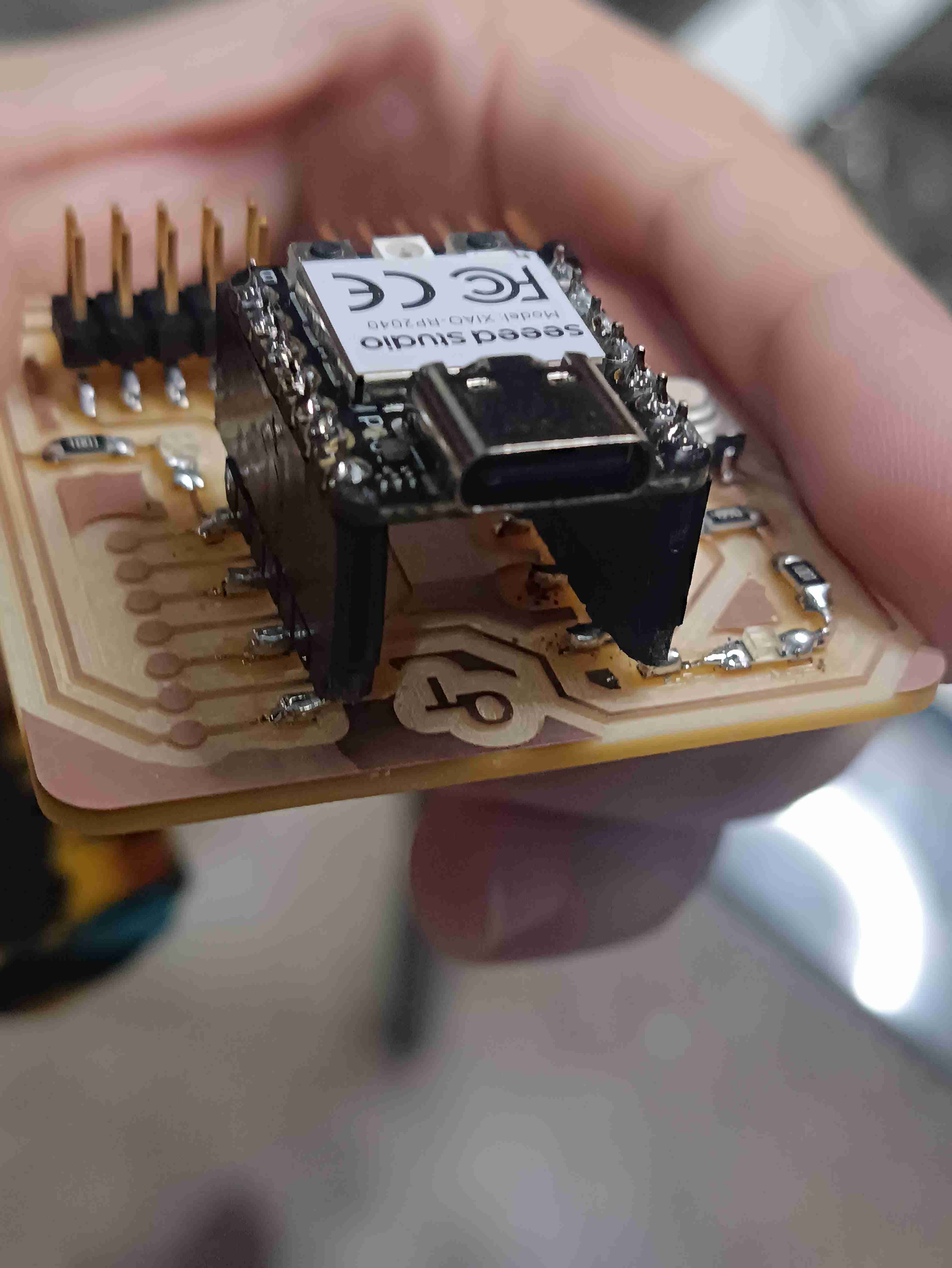
My problem started when I had to place the headers for the xiao on my board. Placing them was pretty hard to do by eye and also soldering was quite a nightmare because if I moved it slightly it wanted to destroy my Paths of the copper in my board. Basically I had a case of Pad lifting in my circuit which means creating a whole new board from scratch.
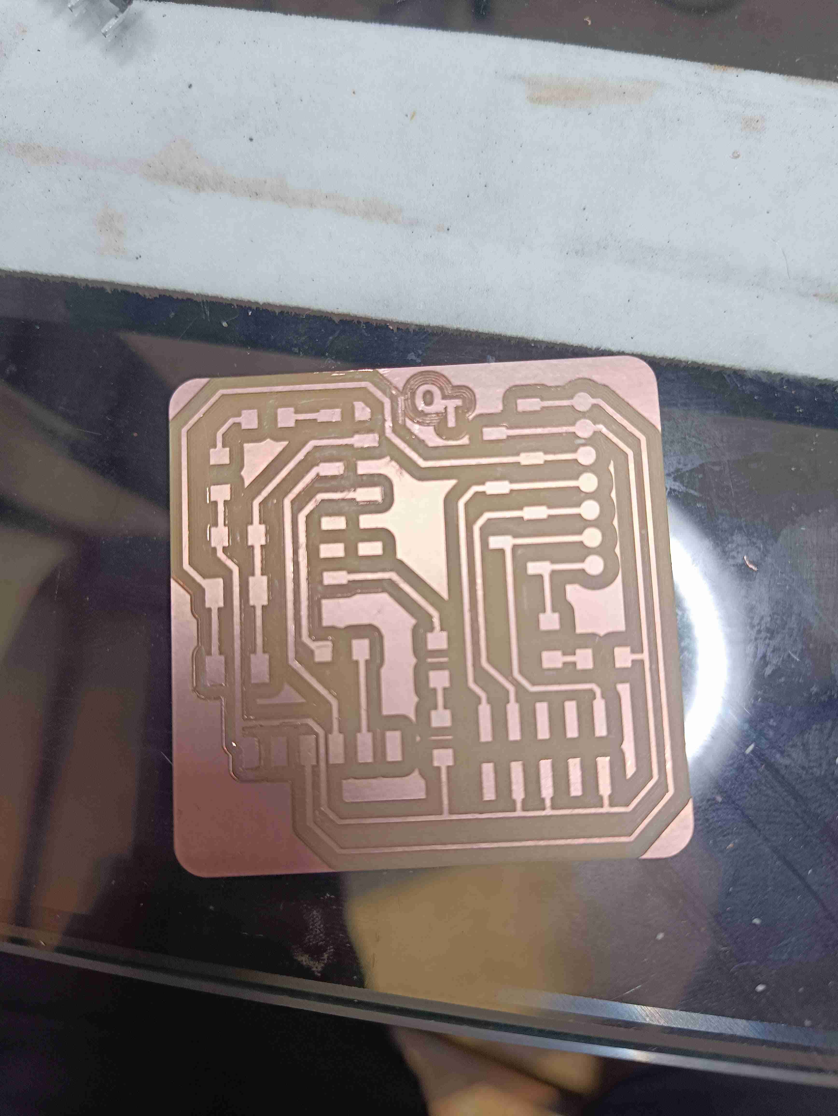
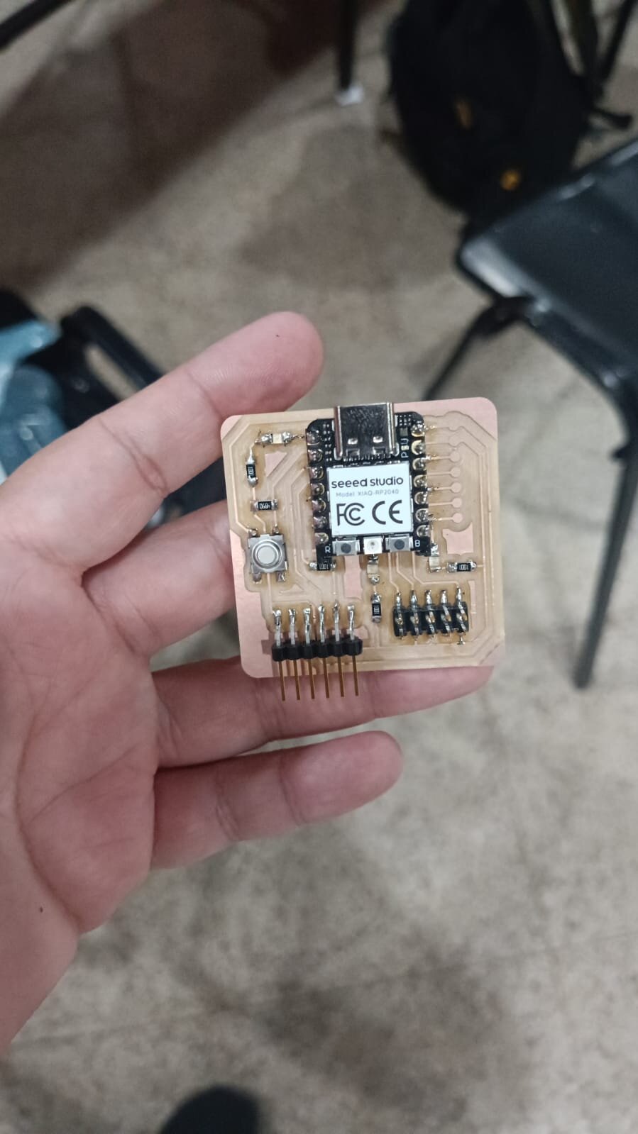
My second attempt with the board was with the optimized board that you saw already in my documentation as pictures.
We basically changed the Connector Heather surface mount 10 position of 1.27 mm for another one that is a little bigger.
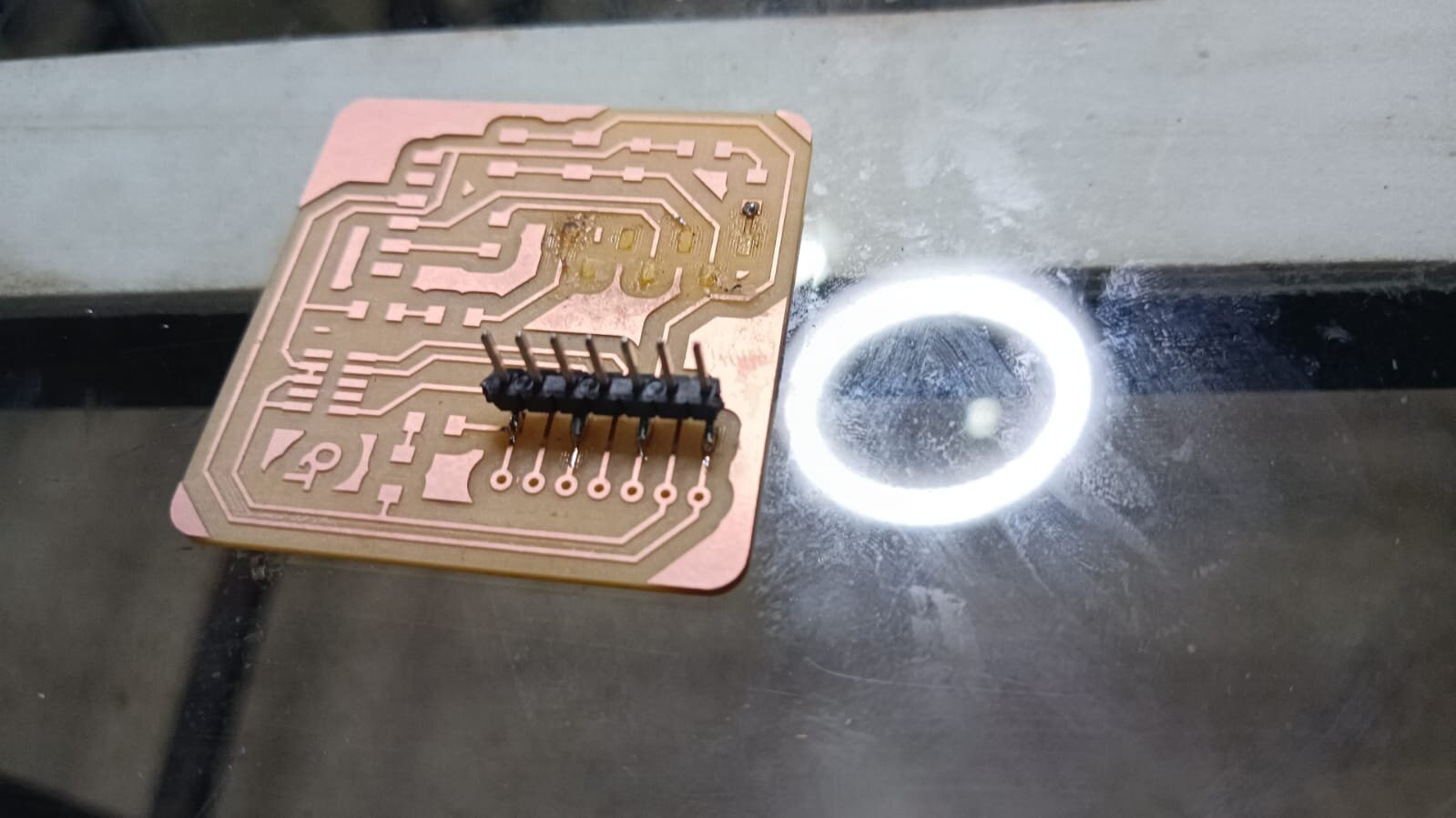
With this new board that was modified because we didn't have the right components in our lab we started soldering and in my case soldering again, but this time I started with the small SMD components like the resistors, the LEDs and the button. For a second time, the copper lifting happened again when I tried to solder the headers, but to my demise it was when I was about to be finished with soldering.
So the third time was the charm. I tried again being very very careful with the section of the headers for the microcontroller and I was finally done with soldering.
After soldering we had to test if the board worked or not and if we put all of the components in the right directions (specially the LEDs and the button).
Programming with MicroPython
Regarding how to program the board my Instructor advised me to use micropython to program. I know you can also use Arduino but since that is something that I have worked with before and apparently micropython is even easier regarding the syntax and it can even have robust programs done on it, I wanted to test it.
What I had to do was look for a version of micro python for our Xiao micro controller, and I know it is a version that uses a Raspberry Pi Pico type of processor so I downloaded the firmware for that.
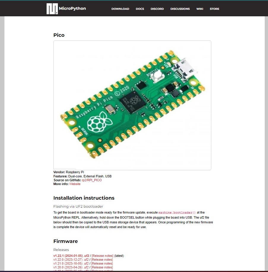
I followed the direction of holding down the boots of the button to plug the board in my USB port so it can be read as a USB and I can basically just copy the framework into the board.
Having done that, I then installed Thonny which is basically like an IDE that allows us to program and access the board in a very easy manner.
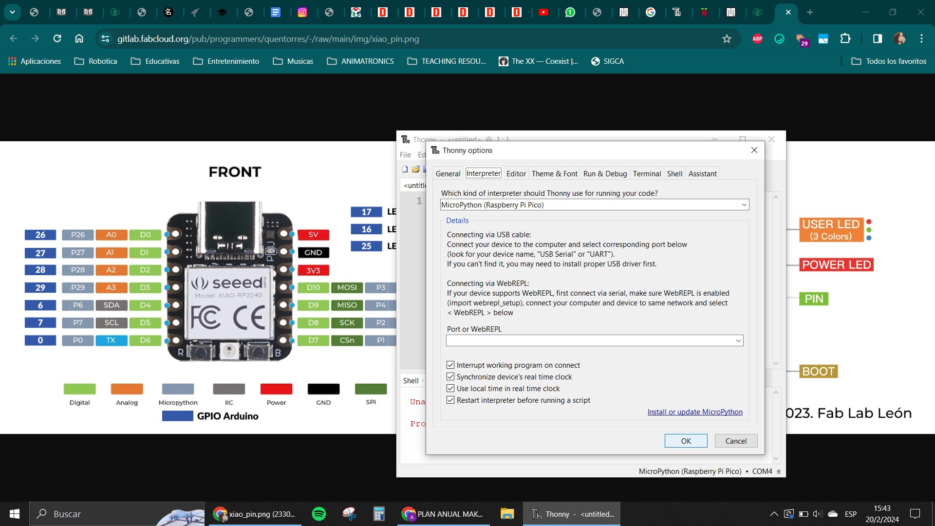
I looked for a base code in Google and it gave me a blink function that I tested to see if my board was working, so I used that and found out where the LEDs were connected in the board and which of the GPIO ports were used for each of them.
Making a test with the one that was in port 26 was my first attempt, and the board was working so I tested the ones in port 1 and 0 as well, and all of them worked nicely with the toggle function :D
Having finished with that, I try to make a more interesting program with a sequence for the LEDs that I asked ChatGPT to help me program.
It also helped me with the program that allowed me to use the button in my board and test it if it was also functioning correctly.
Here is a document where I show what my prompts and answers of ChatGPT were for the process of programming.
and that was it for the week.