Week 3: Computer Controlled Cutting
Objectives of the week:
- Demonstrate and describe parametric 2D modelling processes.
- Identify and explain processes involved in using the laser cutter.
- Develop, evaluate and construct a parametric construction kit.
- Identify and explain processes involved in using the vinyl cutter.
Sections in page:
- Raster to Vectoring
- Vinyl cutter
- Using a heat press
Raster to Vector:
In this week's assignment we had to make a design or use an existing one to cut with the vinyl cutter. I went with the latter, since I haven't practiced this in last weeks assignment. So my idea was to look for a design that I liked to try and put it in a T-shirt.
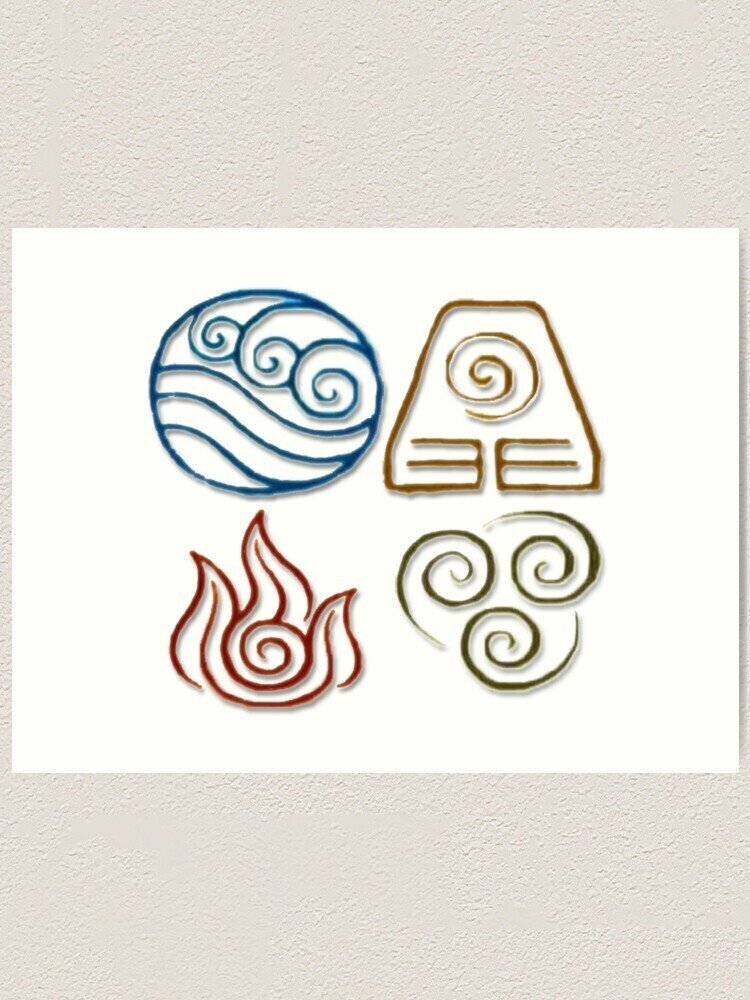
I started looking at some ideas in images for a show that I like a lot named "Avatar The Last Airbender". I wanted the logos of the main bending types.
Then I used a page that helped me understand how to use the tracing in Inkscape. Here is the link to the page that I used!
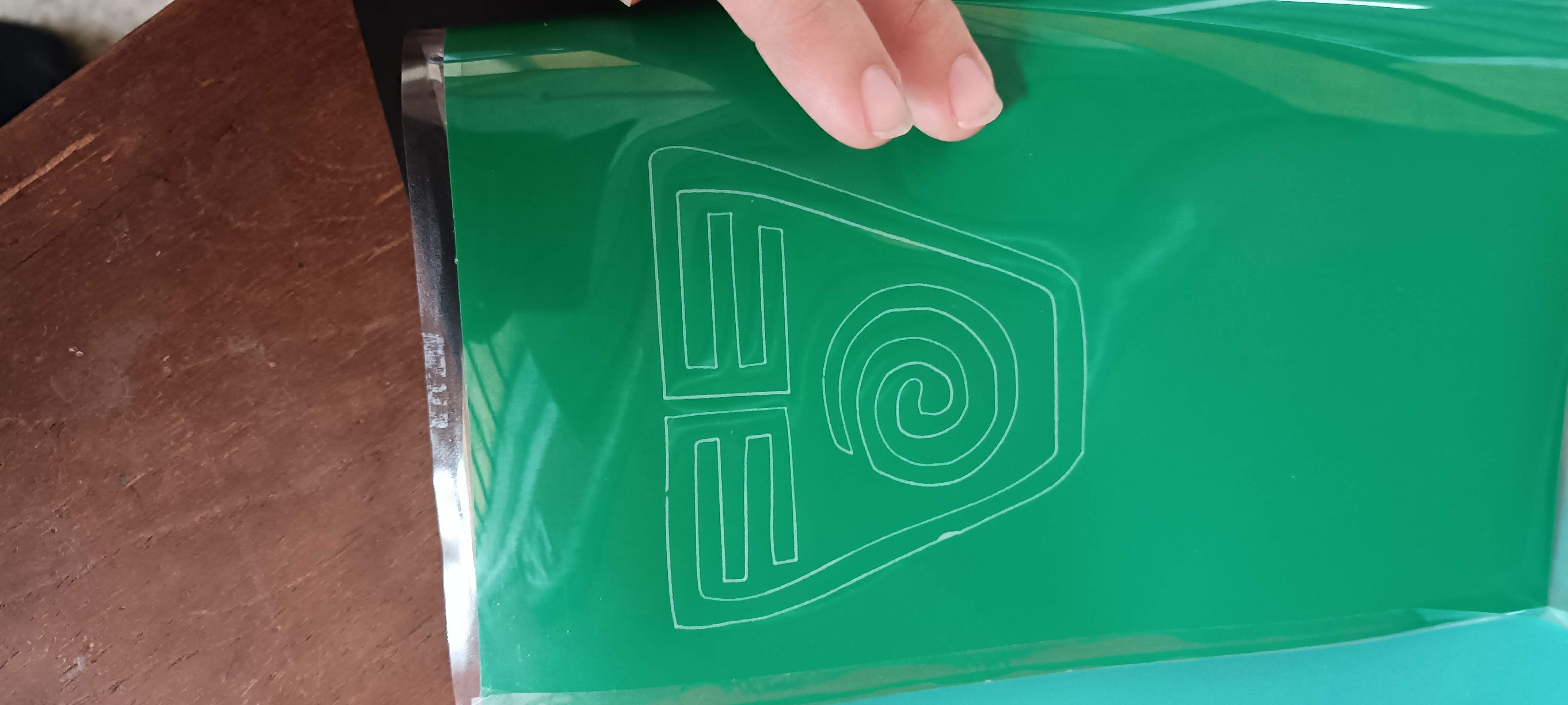
So I grabbed one of the pictures with all the logos, and used the "color quantization" tool in the Trace Bitmaps on inkscape to get the vector.
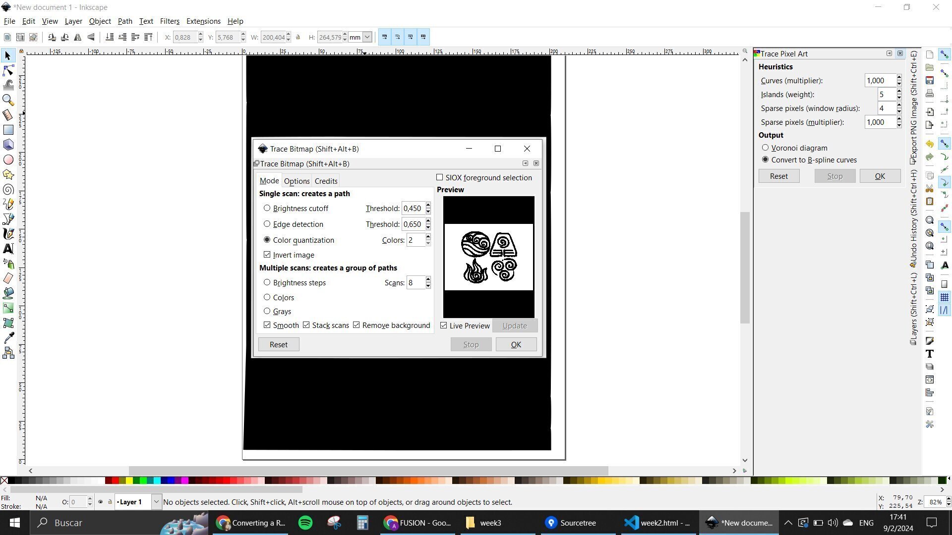
I had the whole image there, even with the background as a vector, so I had to clean it up a bit. Went in with the path nodes tool, and selected the parts that weren't useful to me and deleted them.
Now another thing that I had to do was separate each logo as an individual element. The easiest solution found was to copy and paste the whole image and take them one by one. I colored all of them differently with colors referent to what each of them represent. And started doing the cleaning
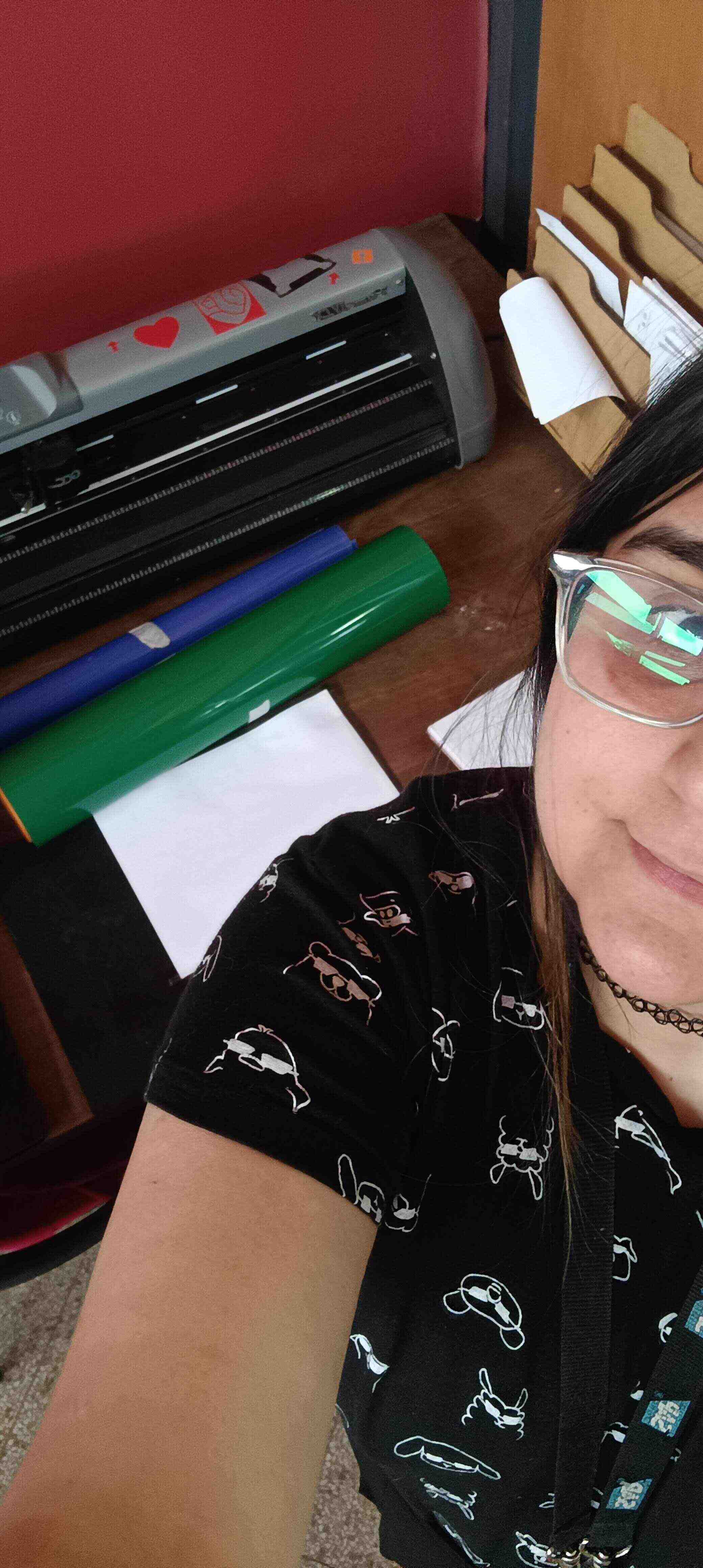
Vinyl Cutter
Having all of the logos ready. It was time to go into the plotter. Now, this was a bit of a process cause my lab's cutter didn't have the license for the official program anymore. So we had to go around it a bit.
I had to install 2 programs: RDWorks that allows me to play with the settings that are going to be used for the machine and save it as a ".plt" file, and another one called "Uploader", that is basically the way to communicate with the machine.
Having both of those programs installed and ready, I went in with starting with some tests with my first designs.
My instructor showed me a step by step that I had to follow for all my future projects:
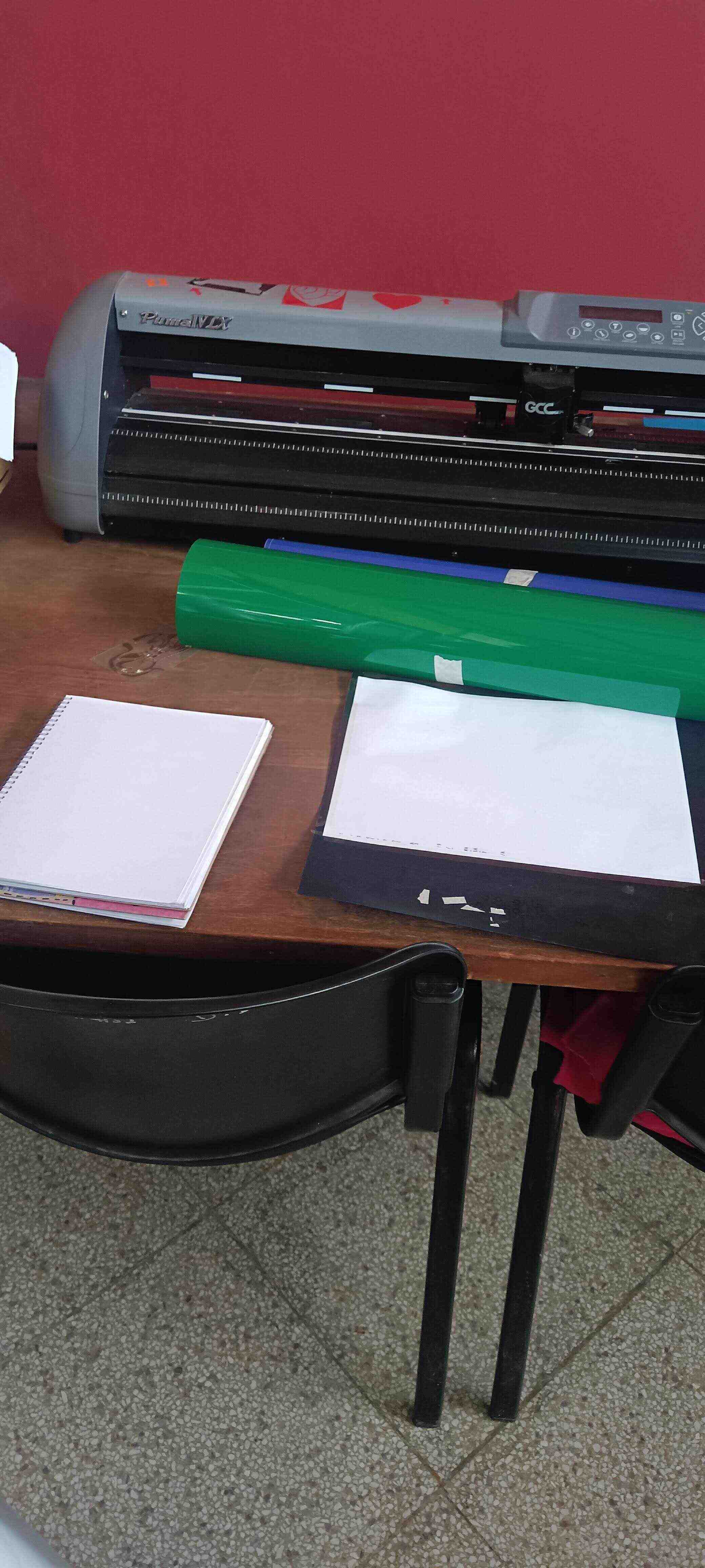
Puma IV Vinyl Cutter:
- Make a design in a vector program
- Export the design as a ".dxf" format
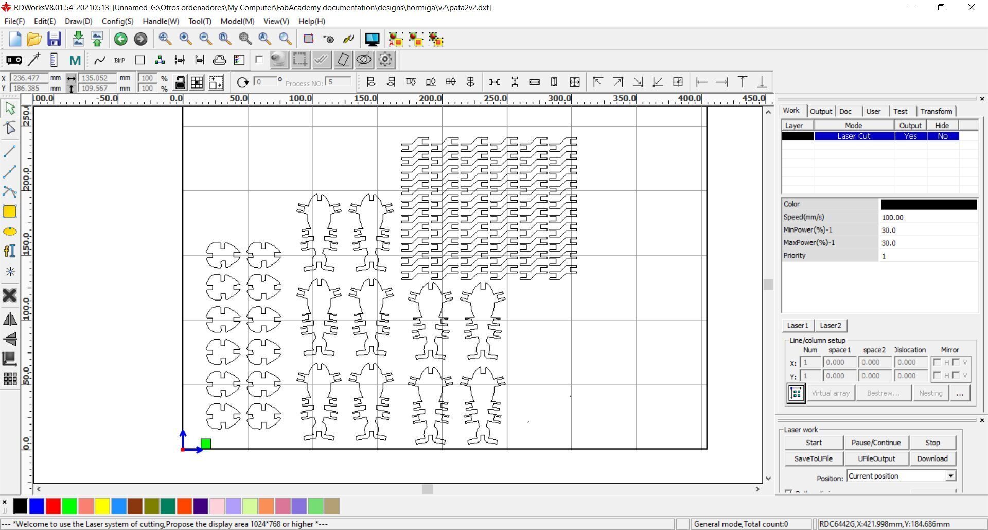
- Open the RDWorks software
- Import the design made in ".dxf"
- Set the size of the mat in RDWorks to fit your needs, for the Puma and the mat we have, this are the settings that work:
- Move the design as near to the origin as possible.
- Export the file with the ".plt" format
- Now open the UpLoader software
- Turn the Puma on, so the software can connect. Once it is linked, you can start working
- Select the port
- Browse for the file.
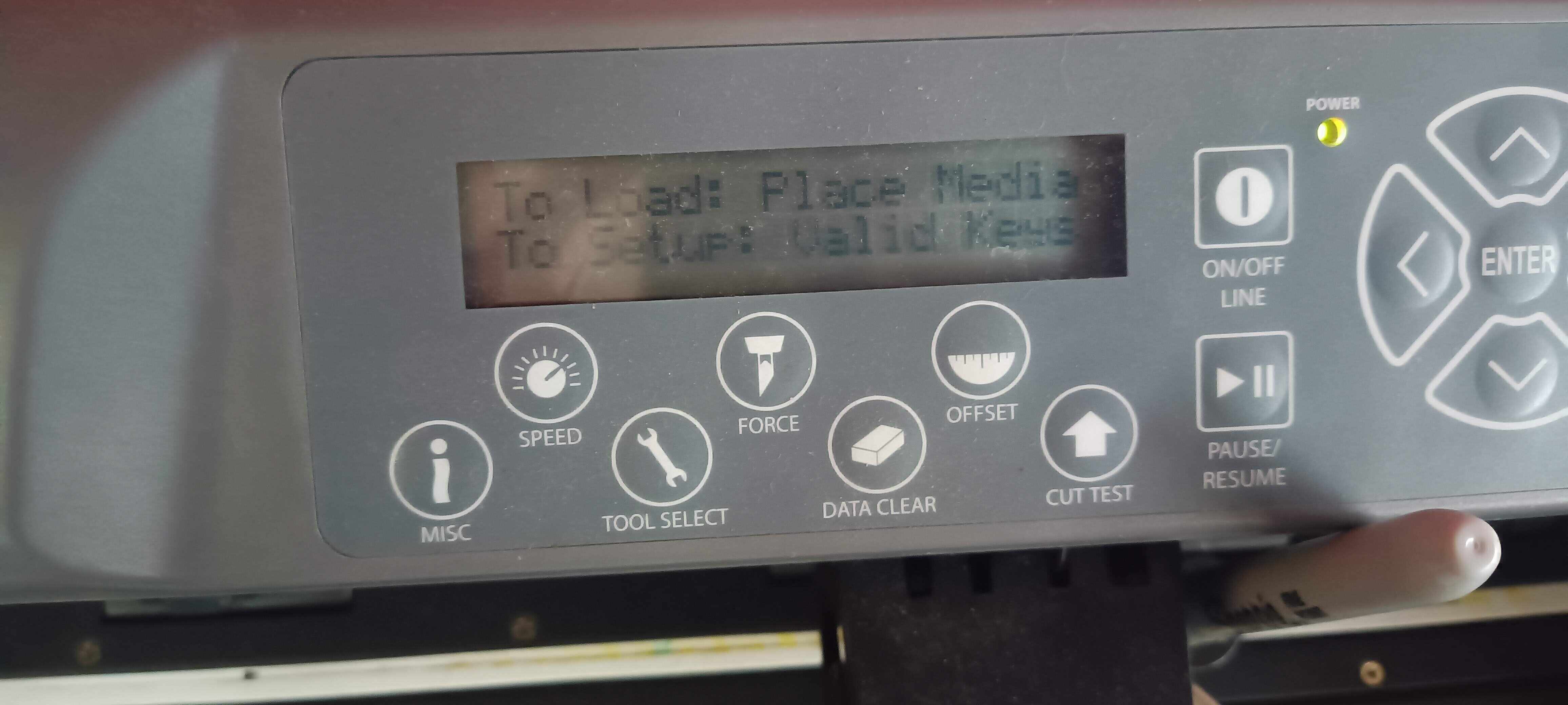
- Before sending the file to the plotter, setting the plotter is important
- Put the material on top of the mat and use masking tape to attach it to it.
- Using the rollers, position the mat so both the top and the bottom one grab the mat.
- Lower the lever on the back to hold the mat on place for the process
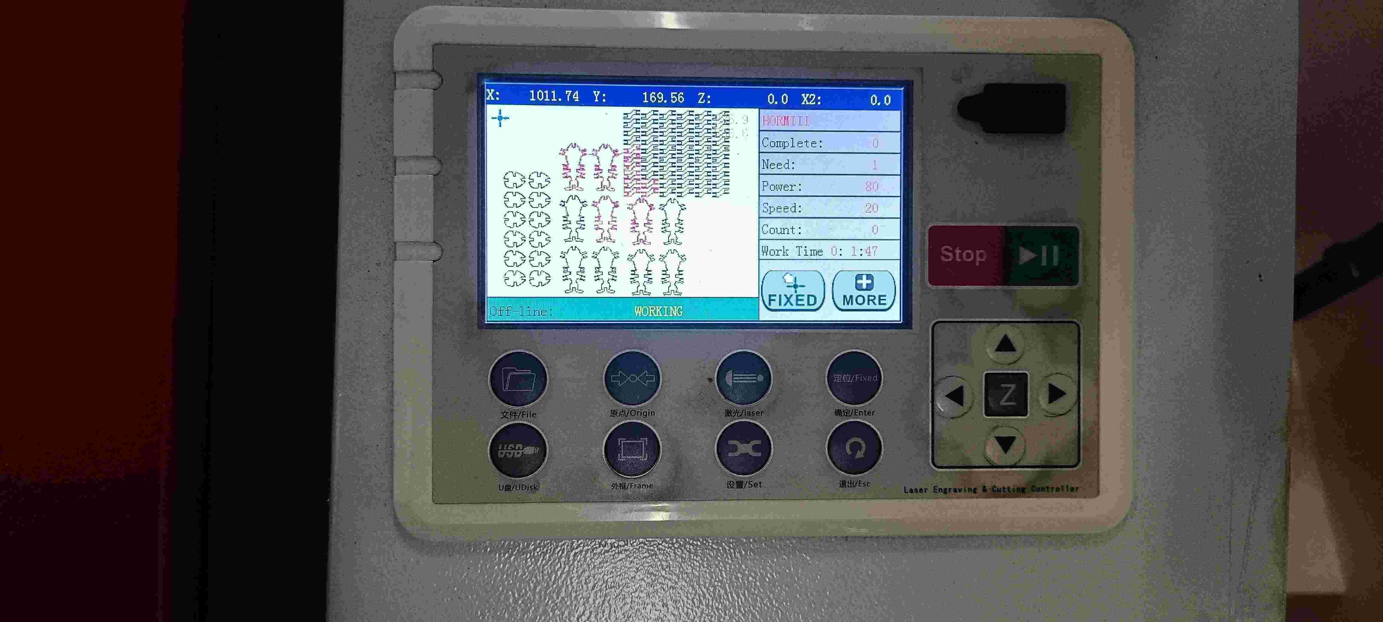
- Now in the display, select the type of work with the ">" button, that accounts for single
- If needed, place the origin on top of the right/bottom corner of the material to cut.
- Set the new origin by pressing the "enter" buttom twice.
- Press start on the software so the process can begin.
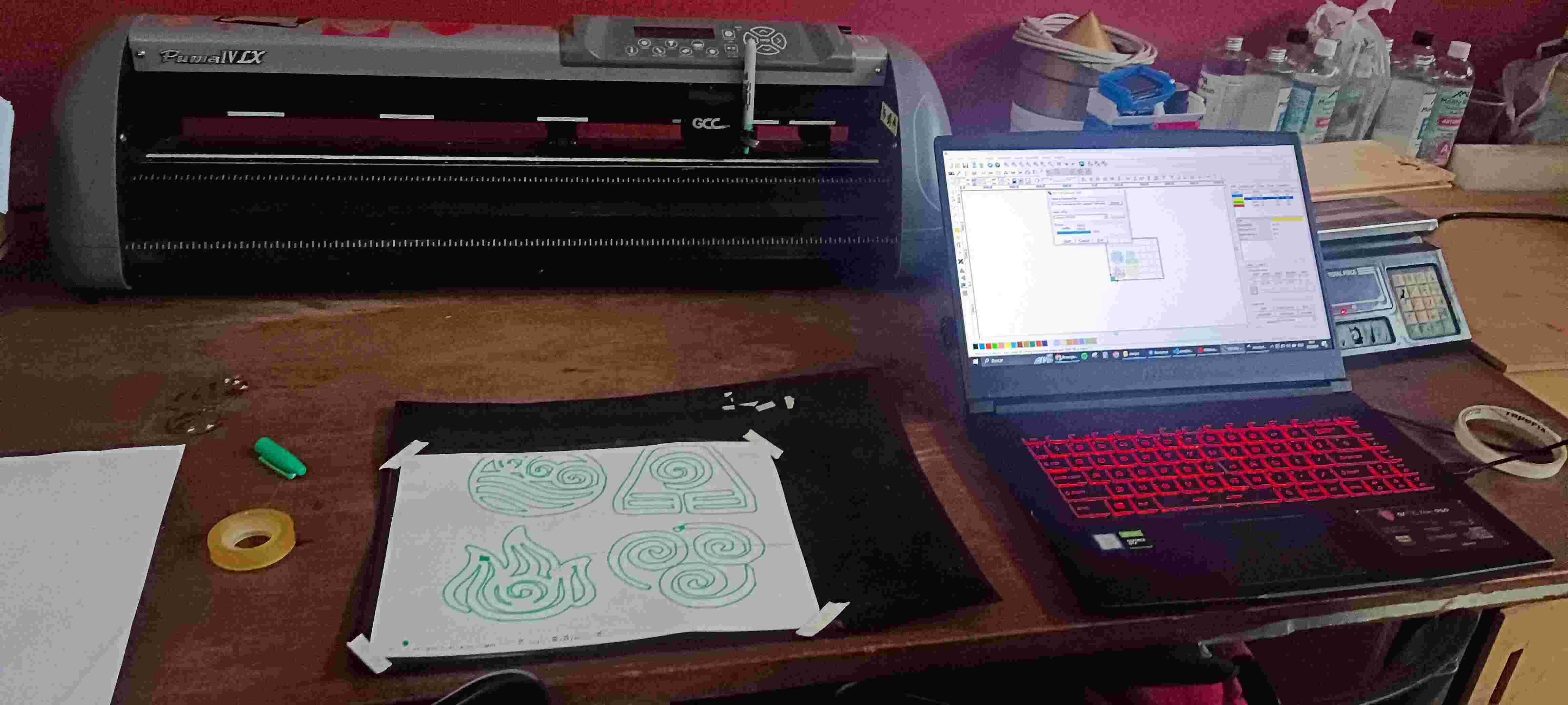
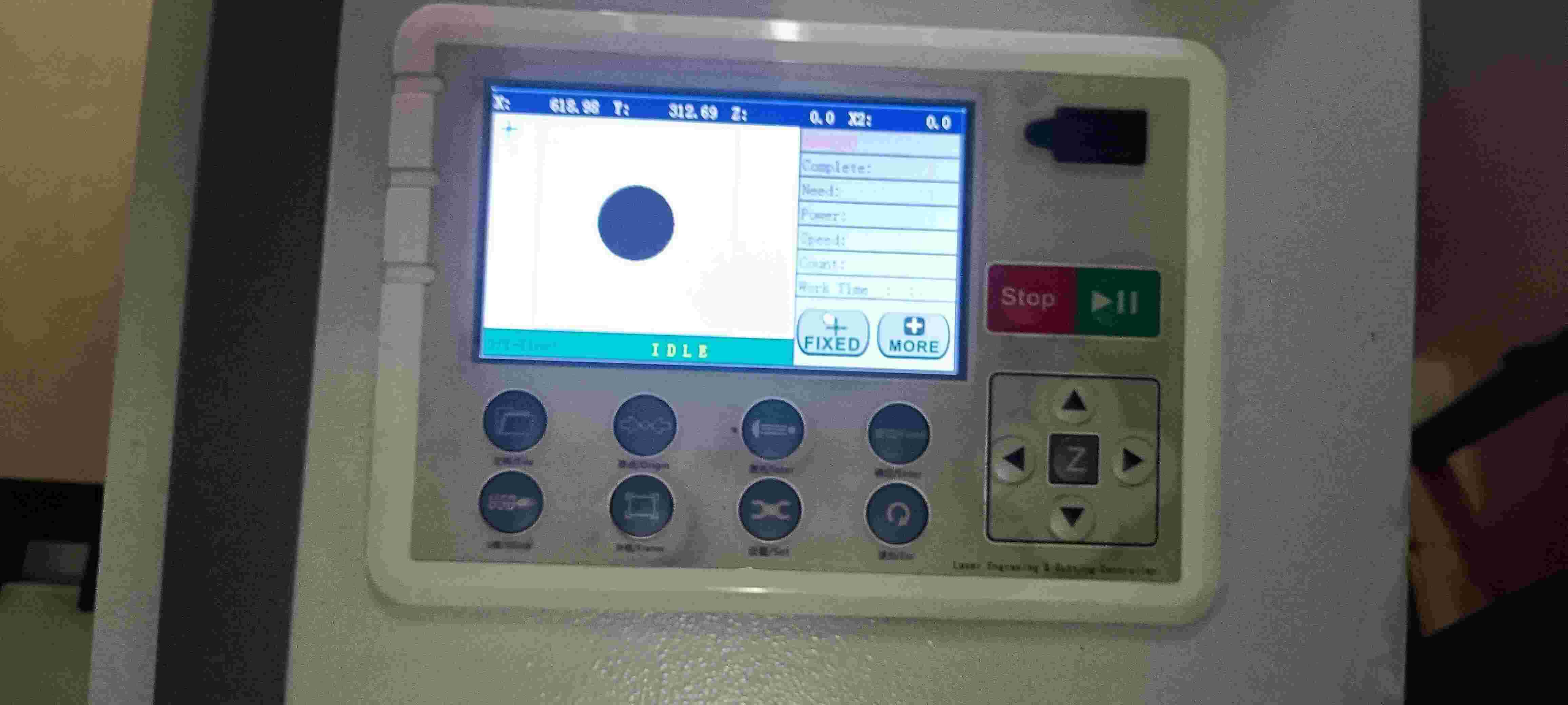
After finishing up with the lesson on how to use the Puma I started to do some tests with some paper.
I uploaded the image in the RD Works program and put it in the origin, gave it some dimensions for it to be tested in the plotter.
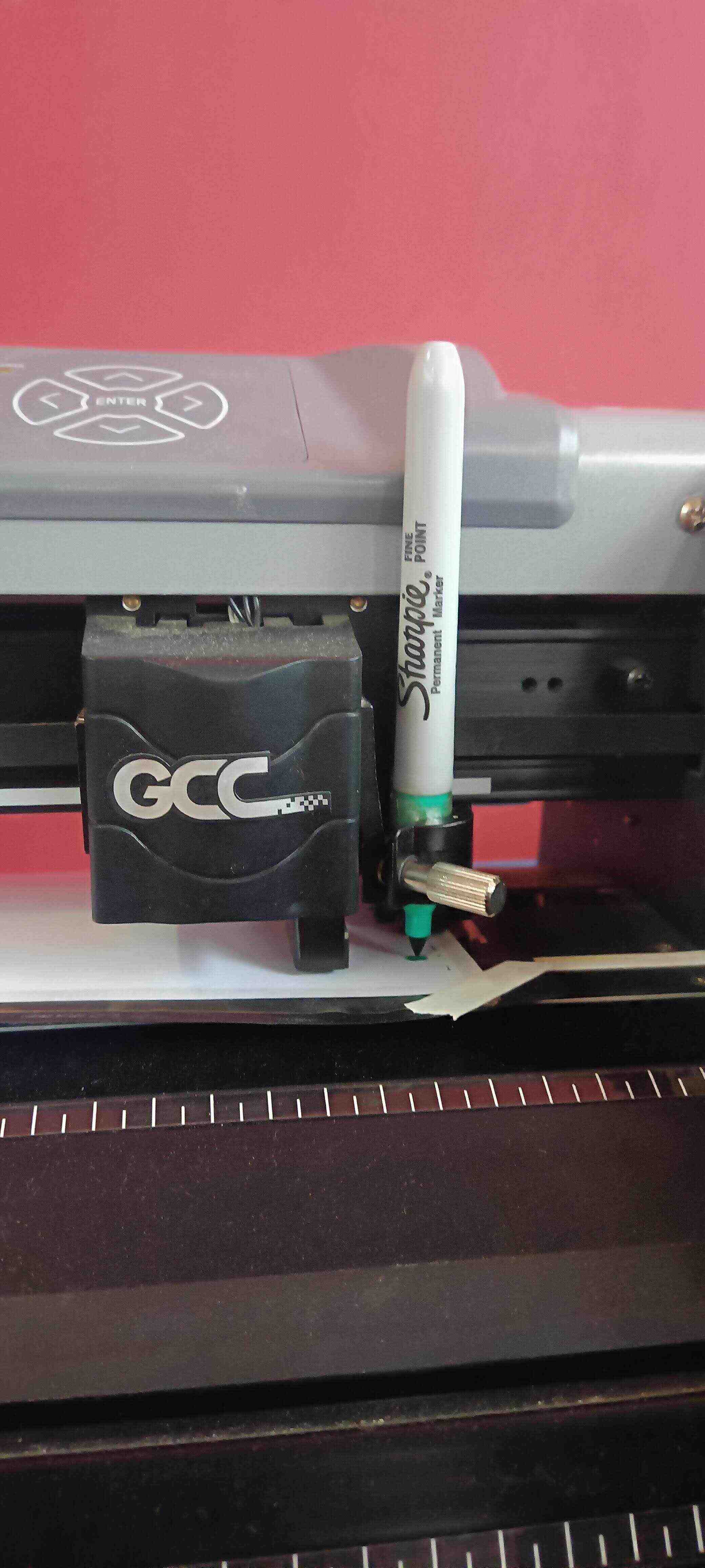
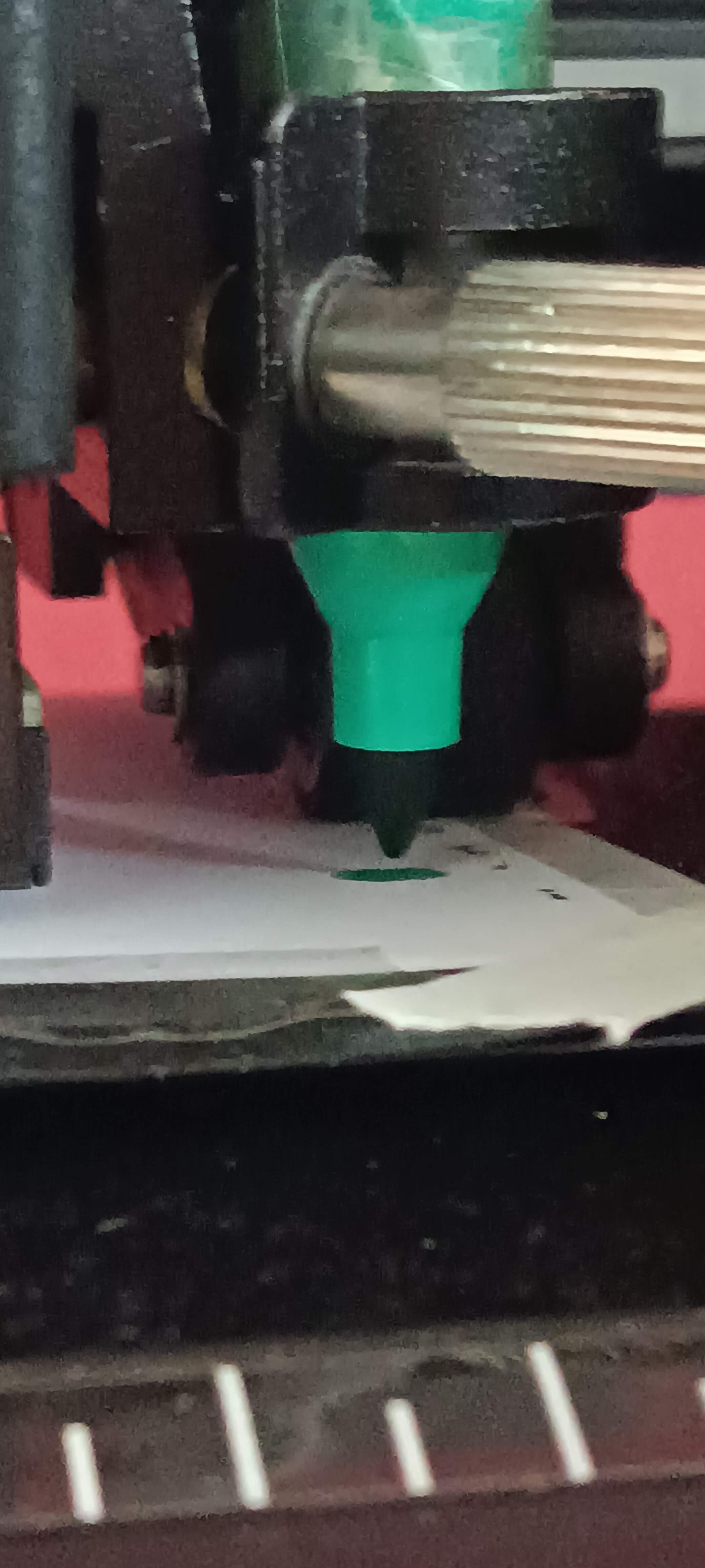
I grabbed a sharpie and put it in the tool grabber and started to make the tests with all the steps mentioned before.
I didn't like how the design looked so I decided to change it later on.
The next few days I tried to change the design because the edges of the vector were too sharp. Found a new image to download and vectorize.
After having the vectors as I needed them, I went ahead and asked to try to cut it with the actual vinyl.
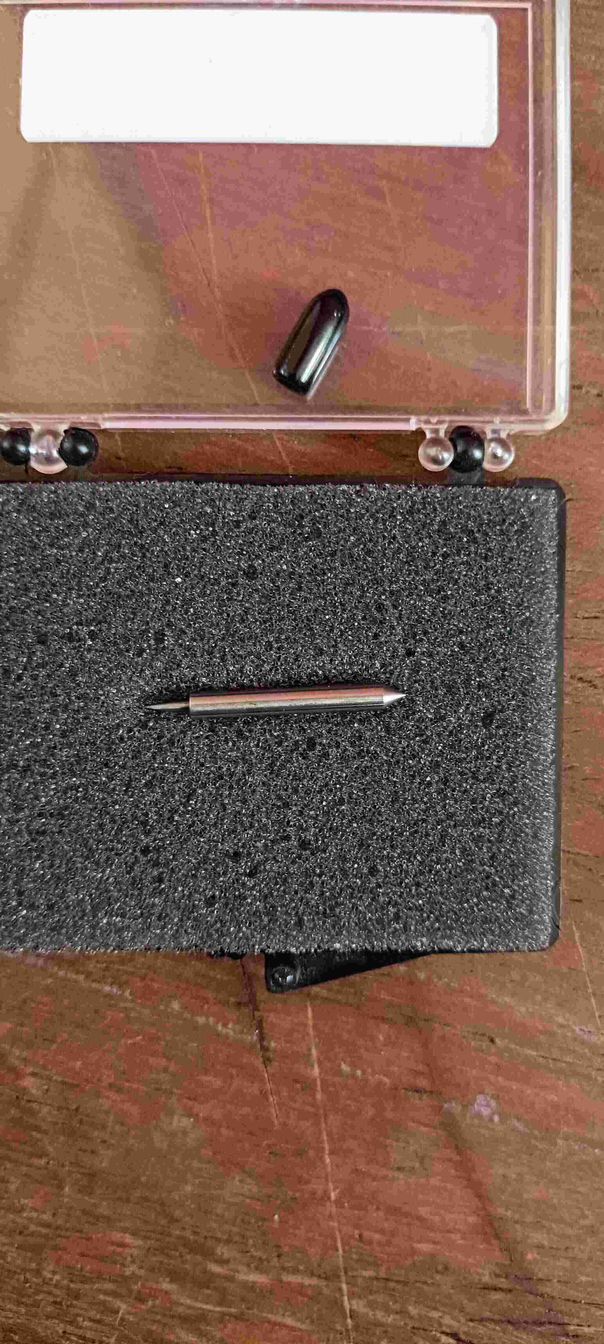
Now for this we had to learn how to use the actual knife, one of our instructors showed us that there are many different types of knives and that we have to be careful because each of them is for a different type of material.
We used the one with the black top because that is the one that cuts the materials that are the thinnest like vinyl.
One important test was to test if the tool was actually cutting vinyl before doing the designs. So we did some tests with the testing option of the machine until we had a nice cut that didn’t go through the whole material.
Another important thing was to attach the vinyl with something like masking tape to the mat, so it is fixed for the process we want to do.
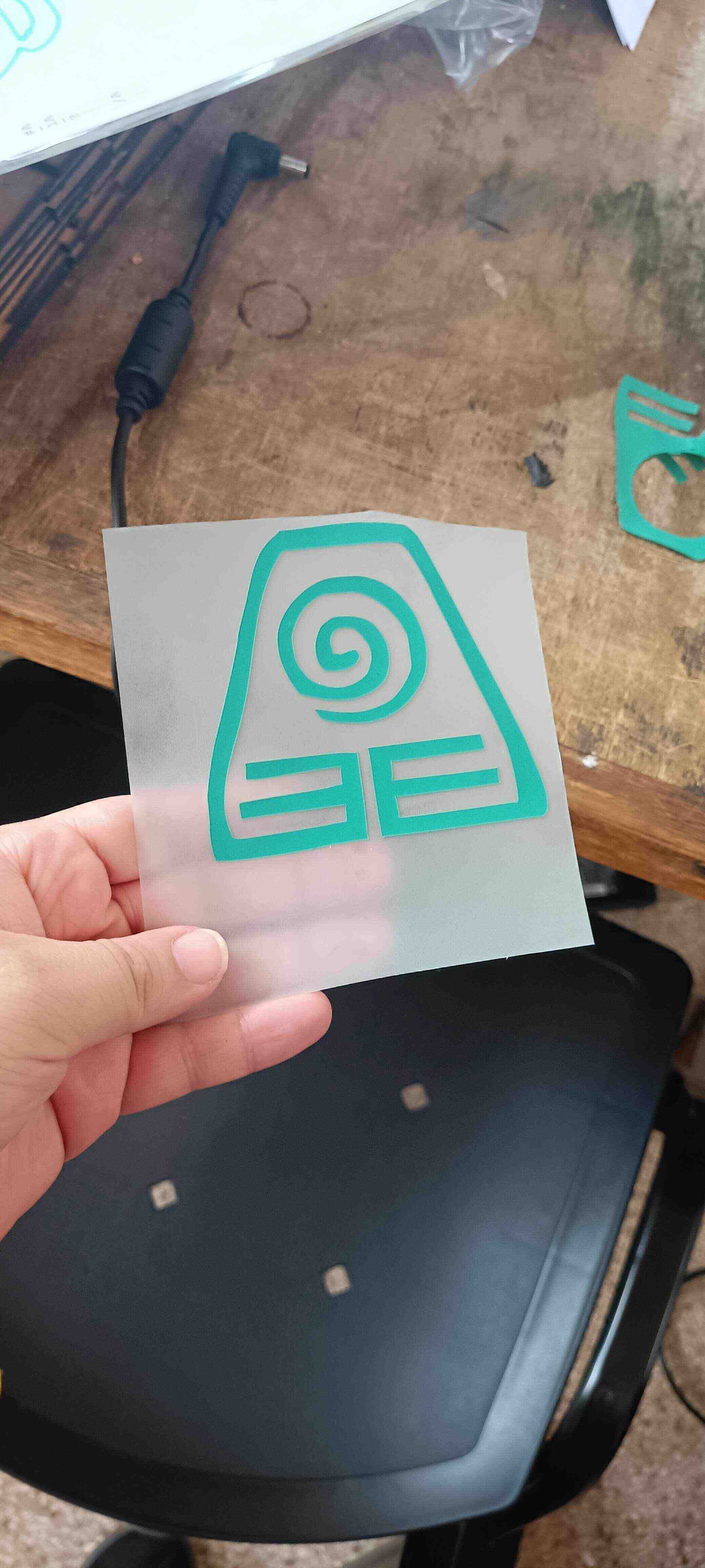
I tried to cut all of the designs in different colors all at once, but had some problems because the tape that I was using to secure them to the mat was actually making the Potter act weird. That's why I decided to make each logo in one file, so they went in separately to cut them.
Some of them worked fine and others actually took me some tries but at the end I had all of the logos that I needed to put in my t-shirt.
After that, what was left to do was to try to use the heat press to create the T-shirt.
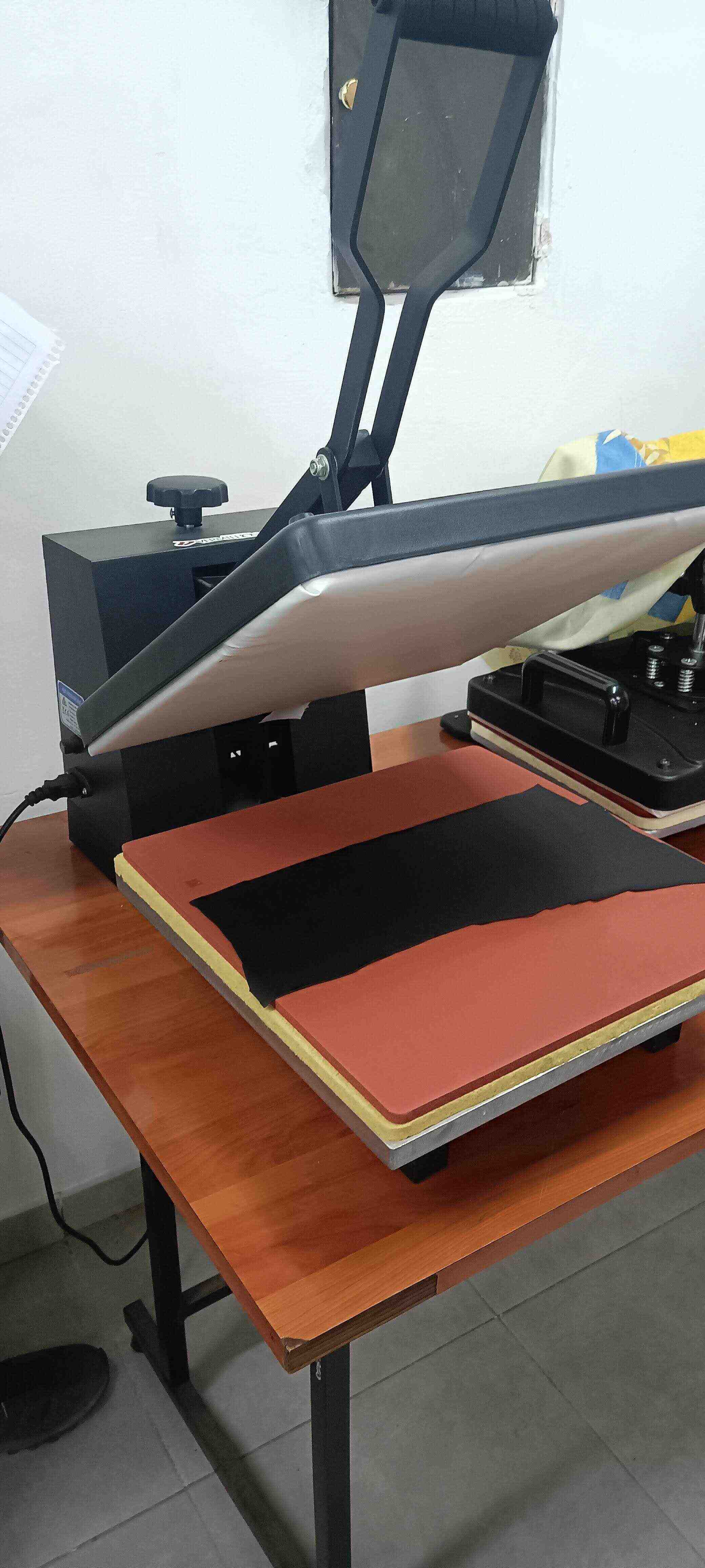
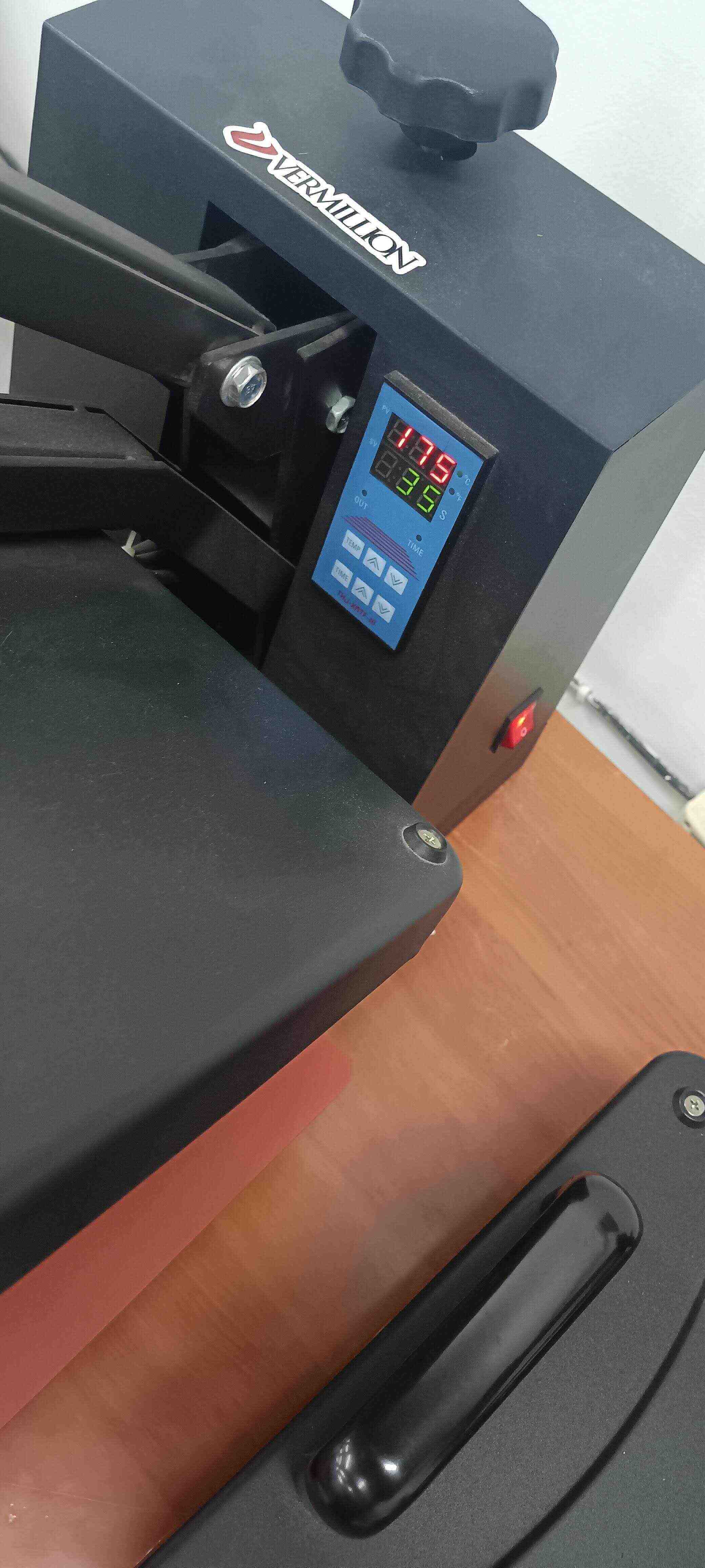
Now we weren’t sure about the temperature and time that was needed for the material, because we didn’t have any exact instructions. So we googled some and we tried some tests. But it still wasn't really working as we needed it.
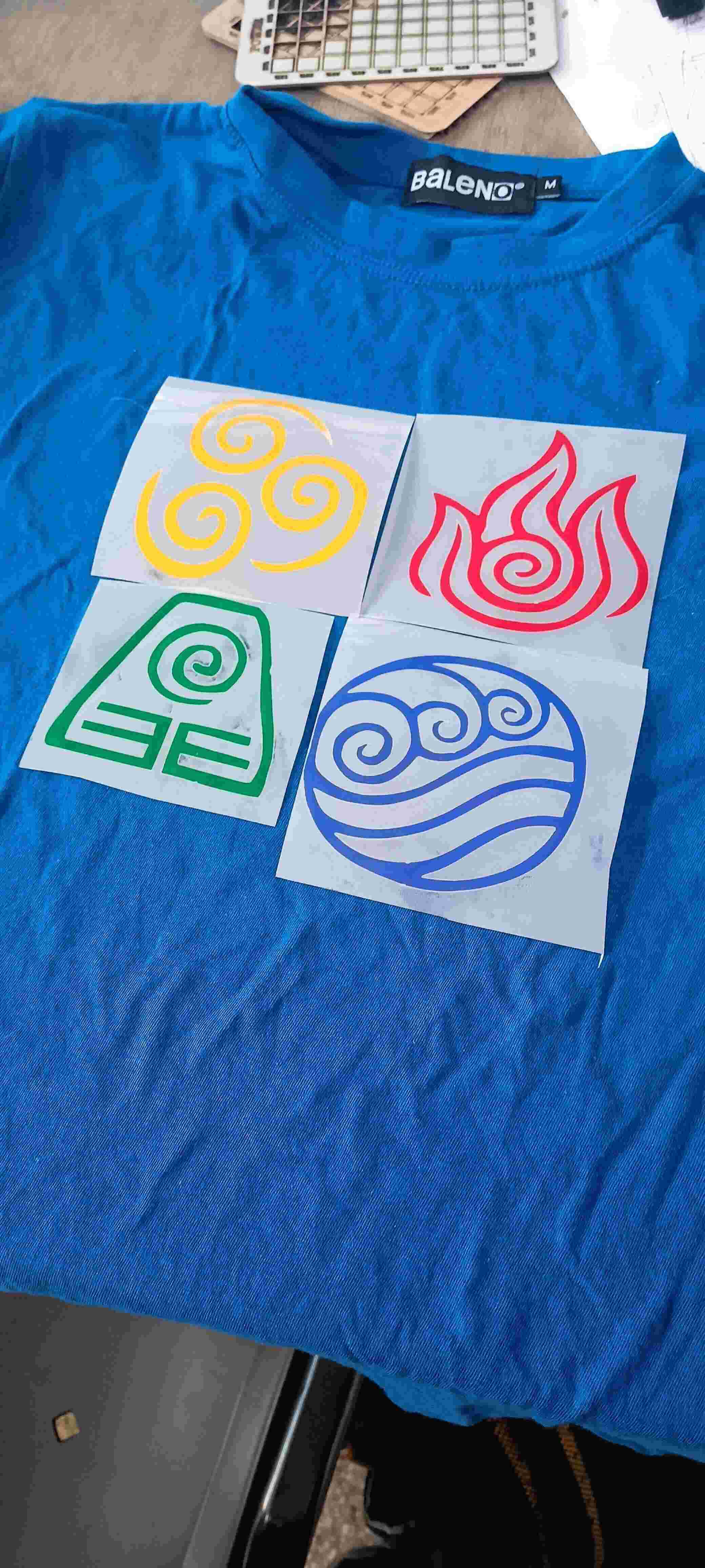
The first test that we tried was with 135 Celsius and for 15 seconds which wasn't enough cause the vinyl wasn’t attached to the shirt.
The 2nd test, we tried with 175 Celsius for 35 seconds and still it wasn't really enough for parts of the design! Only the blue design was ready, and the others were not.
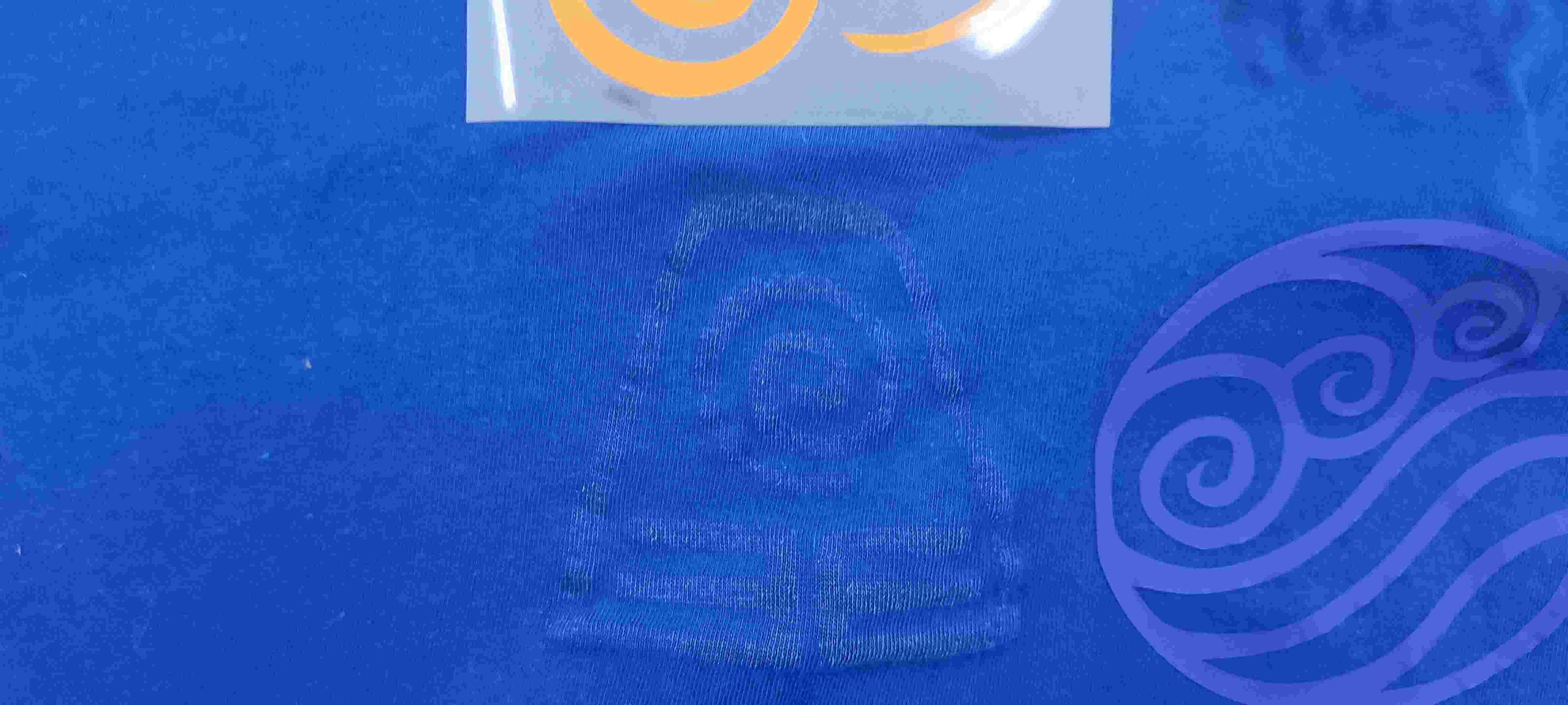
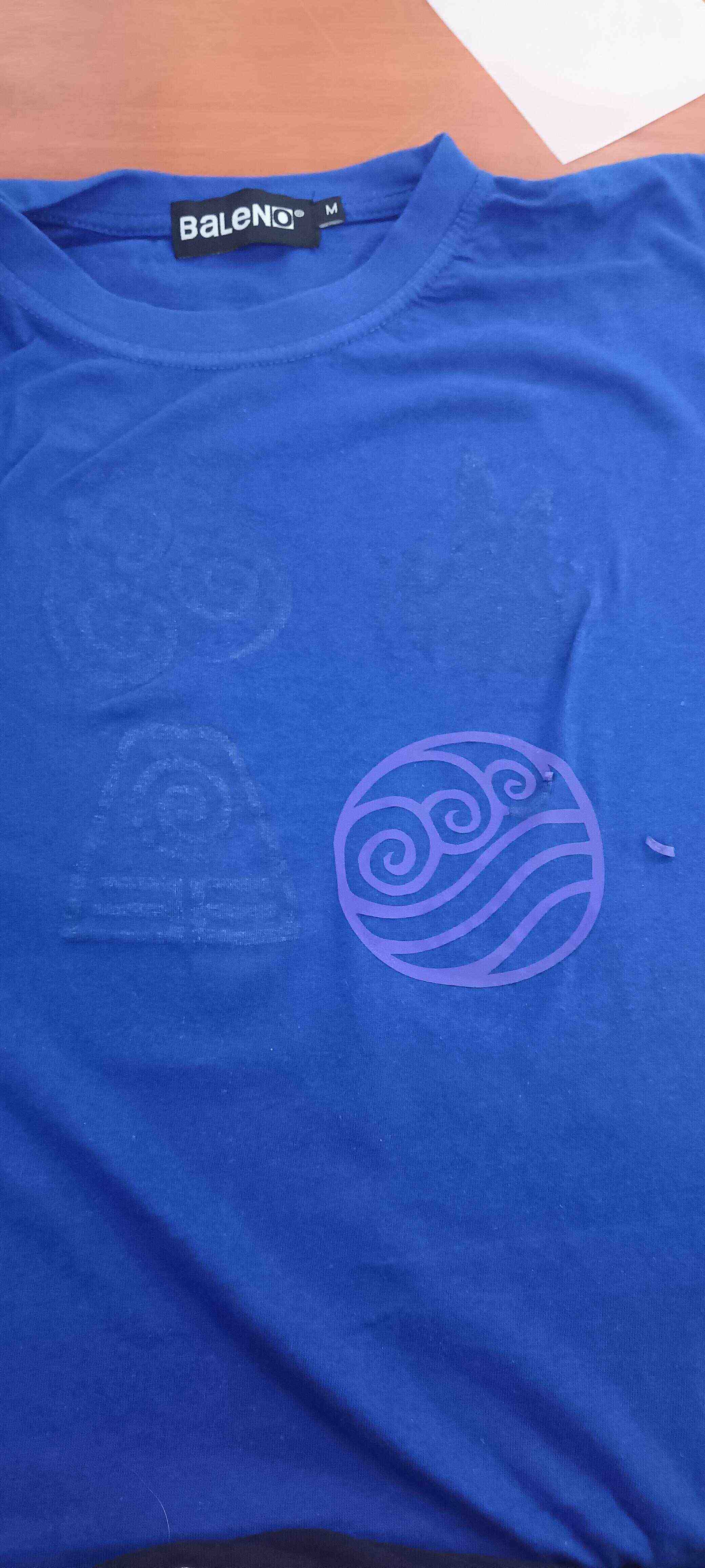
Now that led us to conclude that probably the problem was with the vinyl, that maybe it was old and that it didn't work anymore or something like that, we are not sure. We noticed that actually the only vinyls that were working were the blue and the white one, which were some vinyls that were already in the FabLab, not the ones that were bought for this occasion.
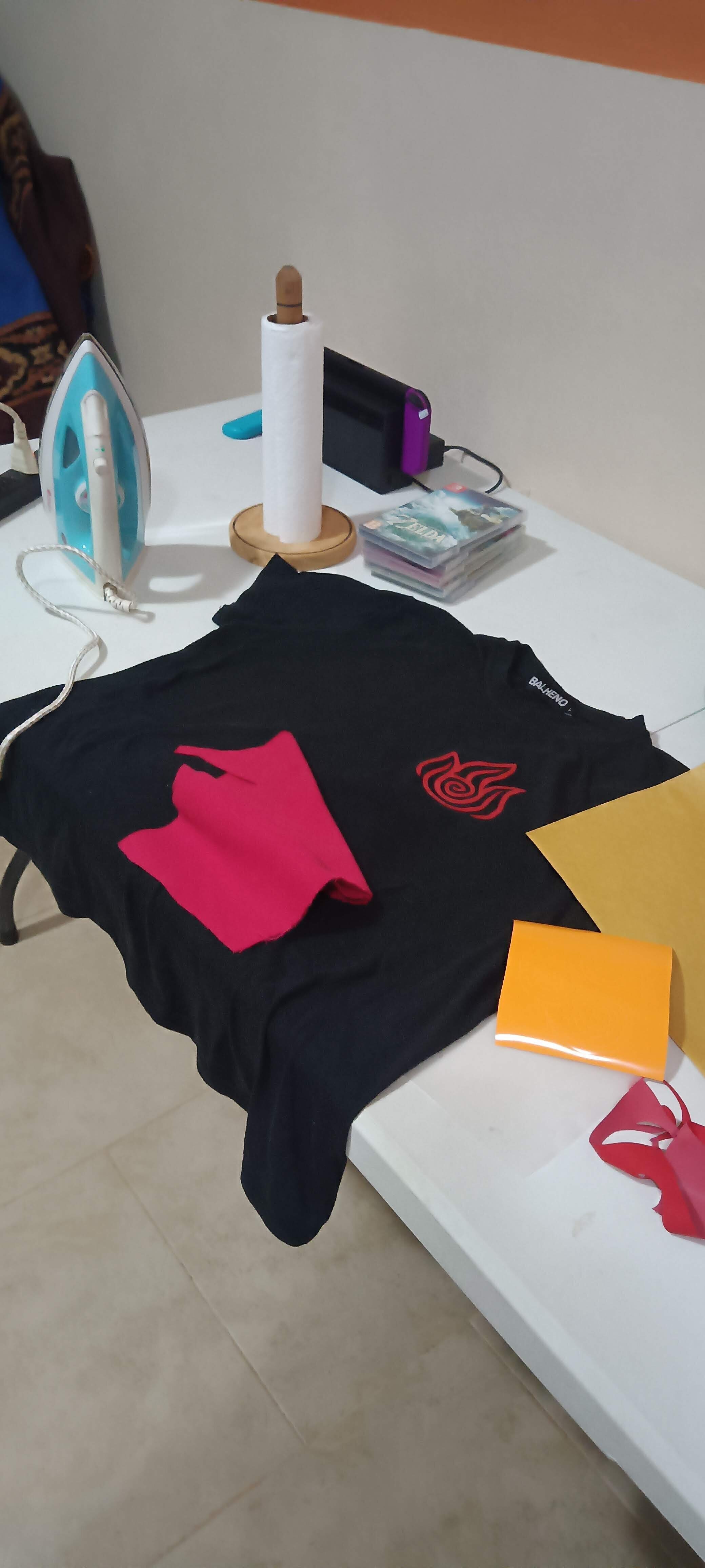
I actually went to my house and tried it again with an iron to see if I had better luck.
The test in my house wasn't as successful either, the only successful one was the one that was with the blue and white one.
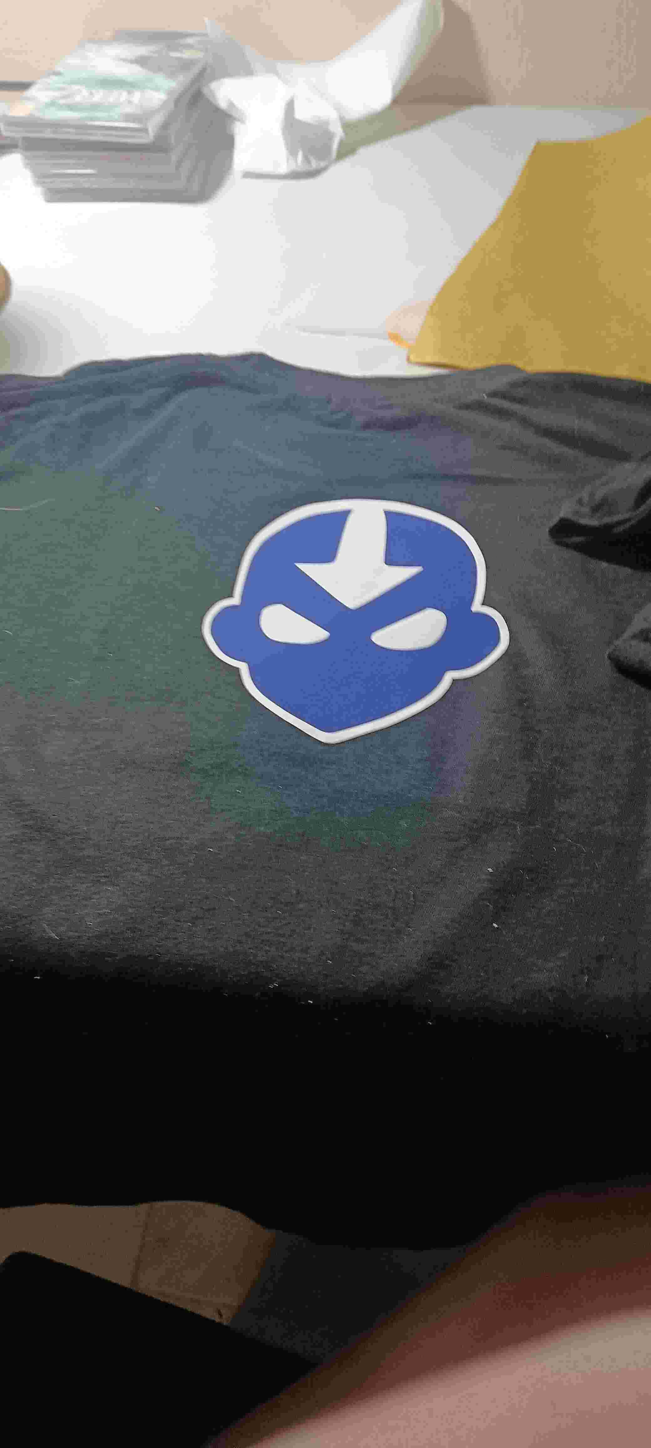
I made another logo with Aang's face, the main character from the series, in which I wanted to test how 2 colors would do. I first put on the white which was sort of the background, and then, on the top, a blue center part which you can see here, that one turned out pretty awesome.

Sadly in my other tests only the blue and the red one worked. The green one was impossible and the orange one also was almost impossible. There were some parts that were attached to the wool but most of it just came out again.
using the laser cutter
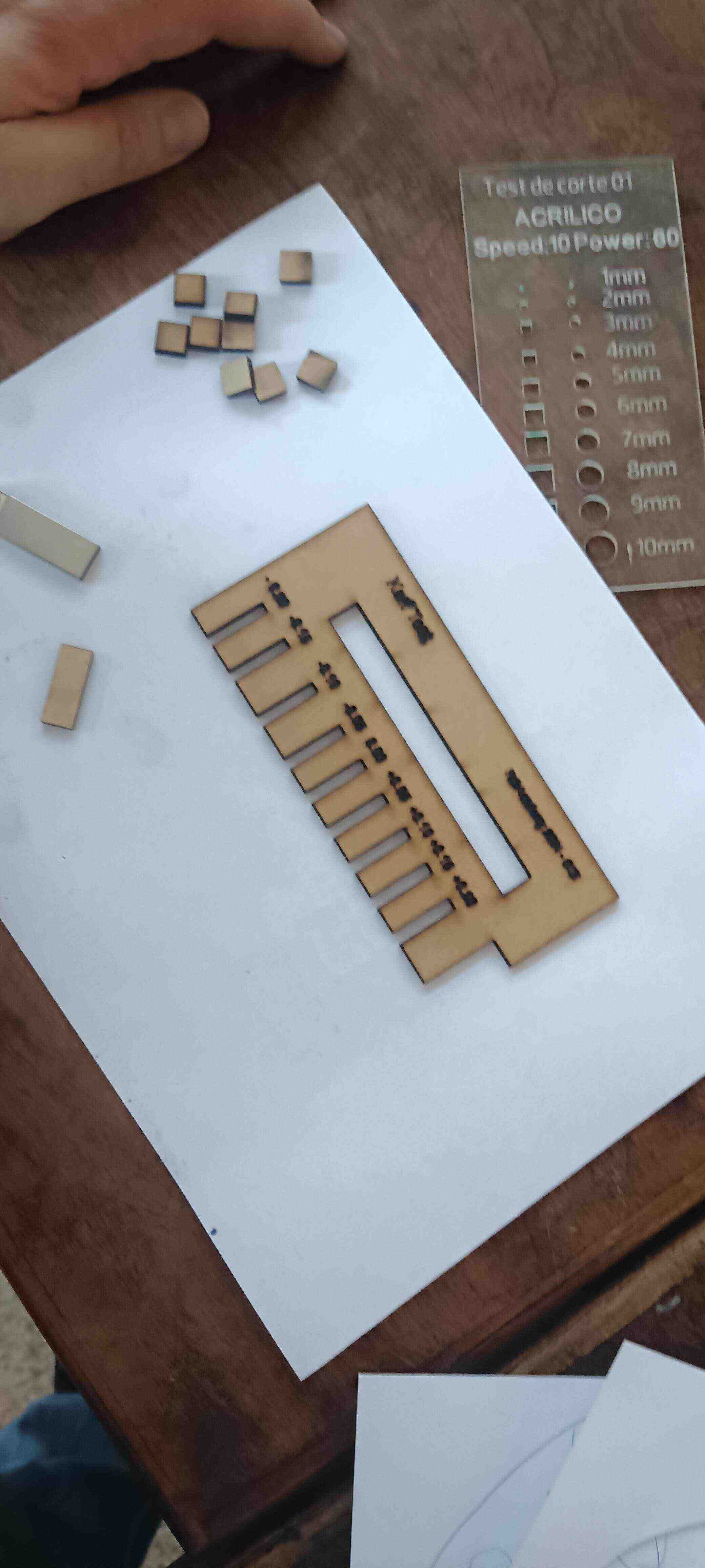
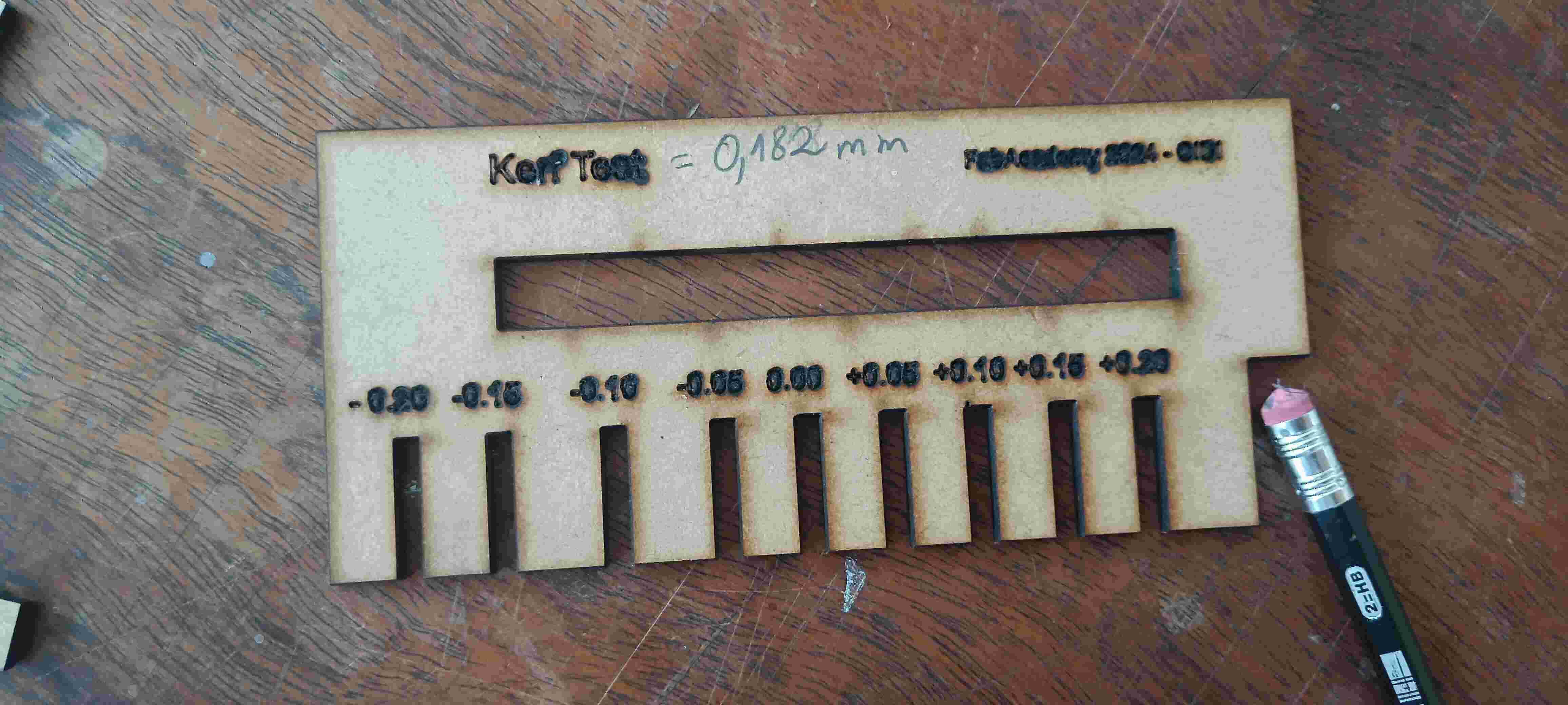
Now in Terms of the laser cutter we actually had a lot of practice with all of my classmates. We decided to do tests with different materials for the kerf, the speed and power. I choose some type of cardboard that is usually called gray cardboard here. I'm not sure if it has another name outside of Paraguay.
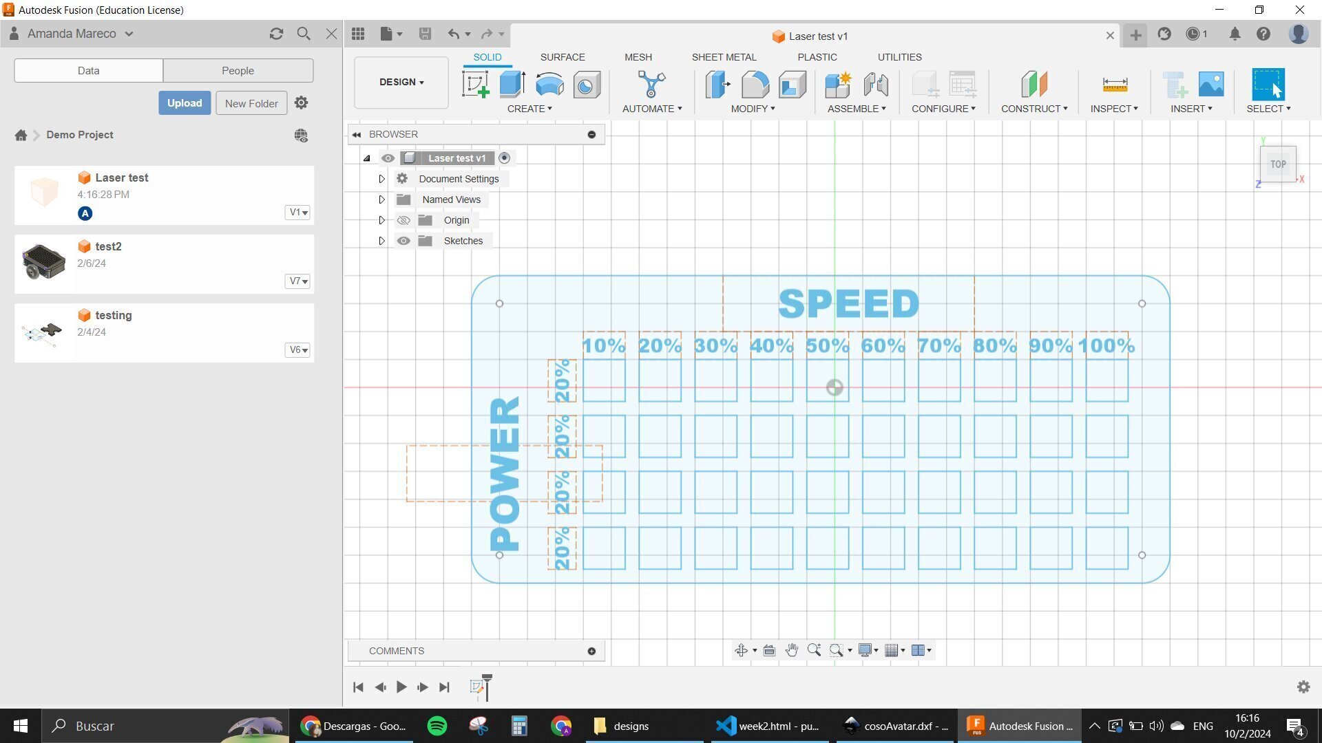
I designed a speed and Power table for my tests and one of my teammates lent me their design for the kerf test.
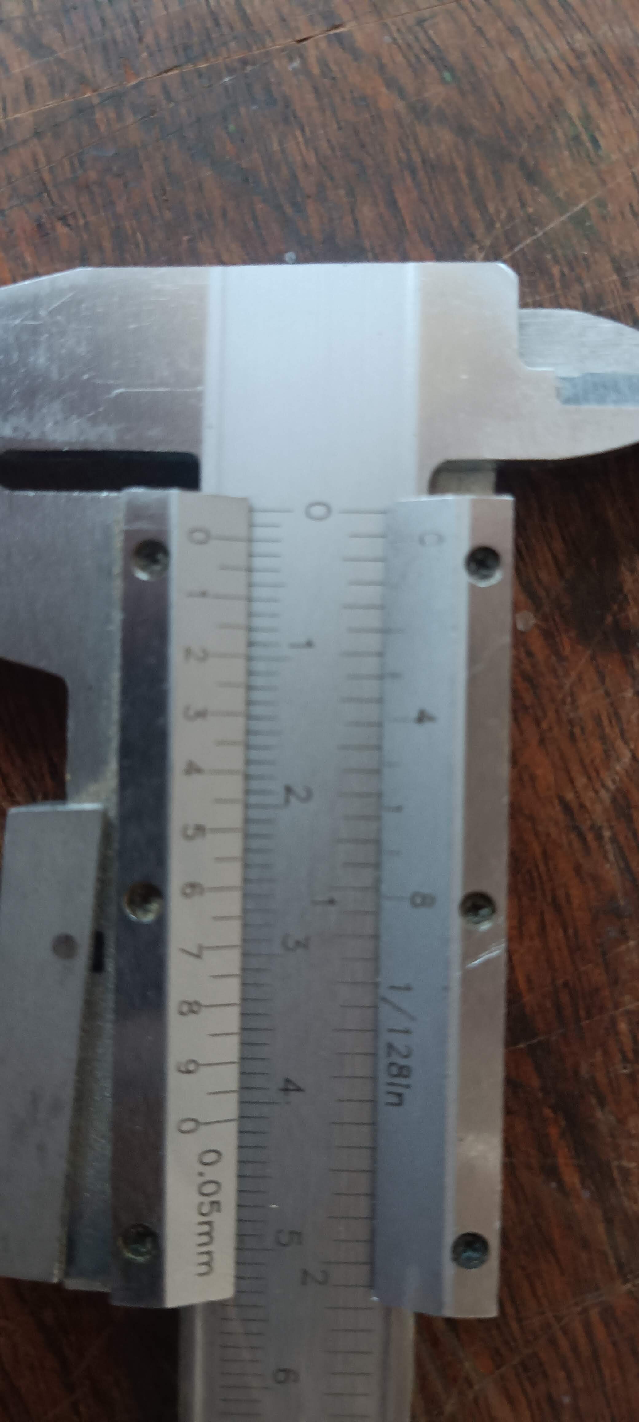
We found the kerf for the MDF wood that is shown here and this is the one that we're going to use for our projects.
All of the information about the laser cutter is going to be available in our group's assignment page, but regardless of that here is a summary.
We basically learned how to turn it on safely, how to use a new program and also how to upload and cut our designs in the laser cutter, here I will leave a step by step:
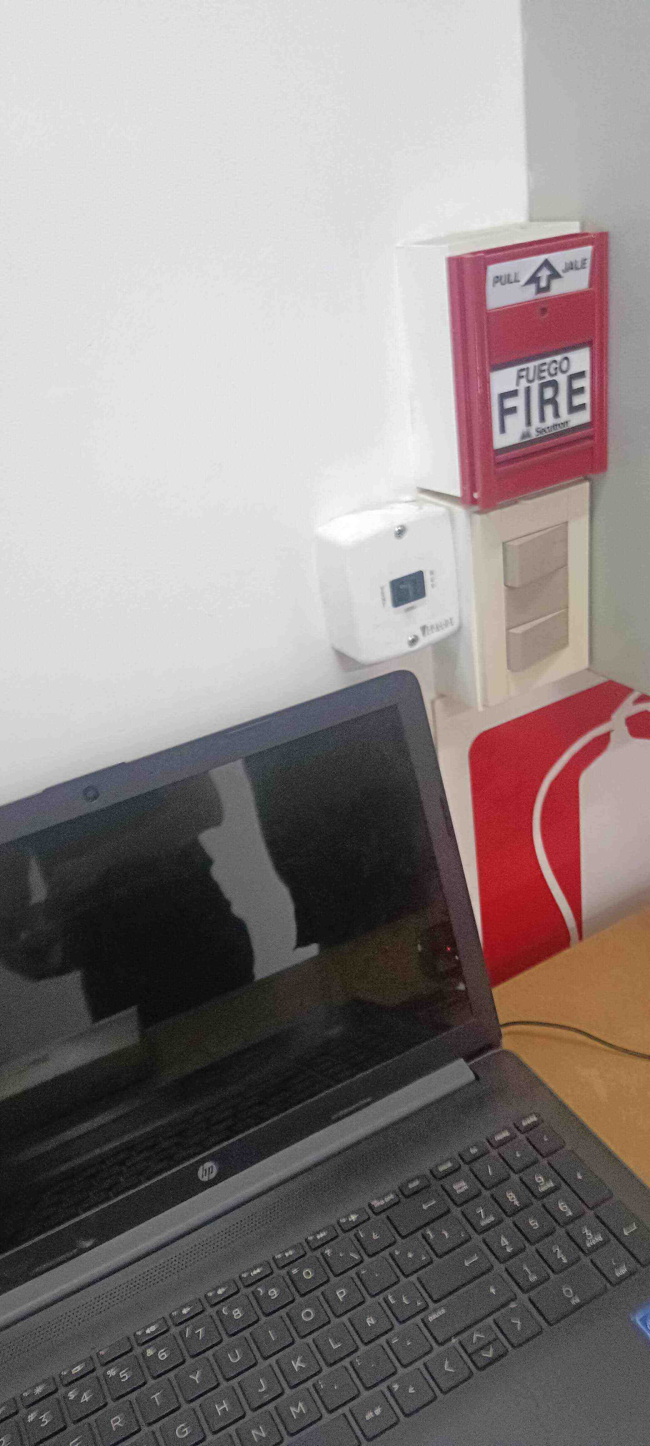
- turning on the extractor which is a white box with a black switch
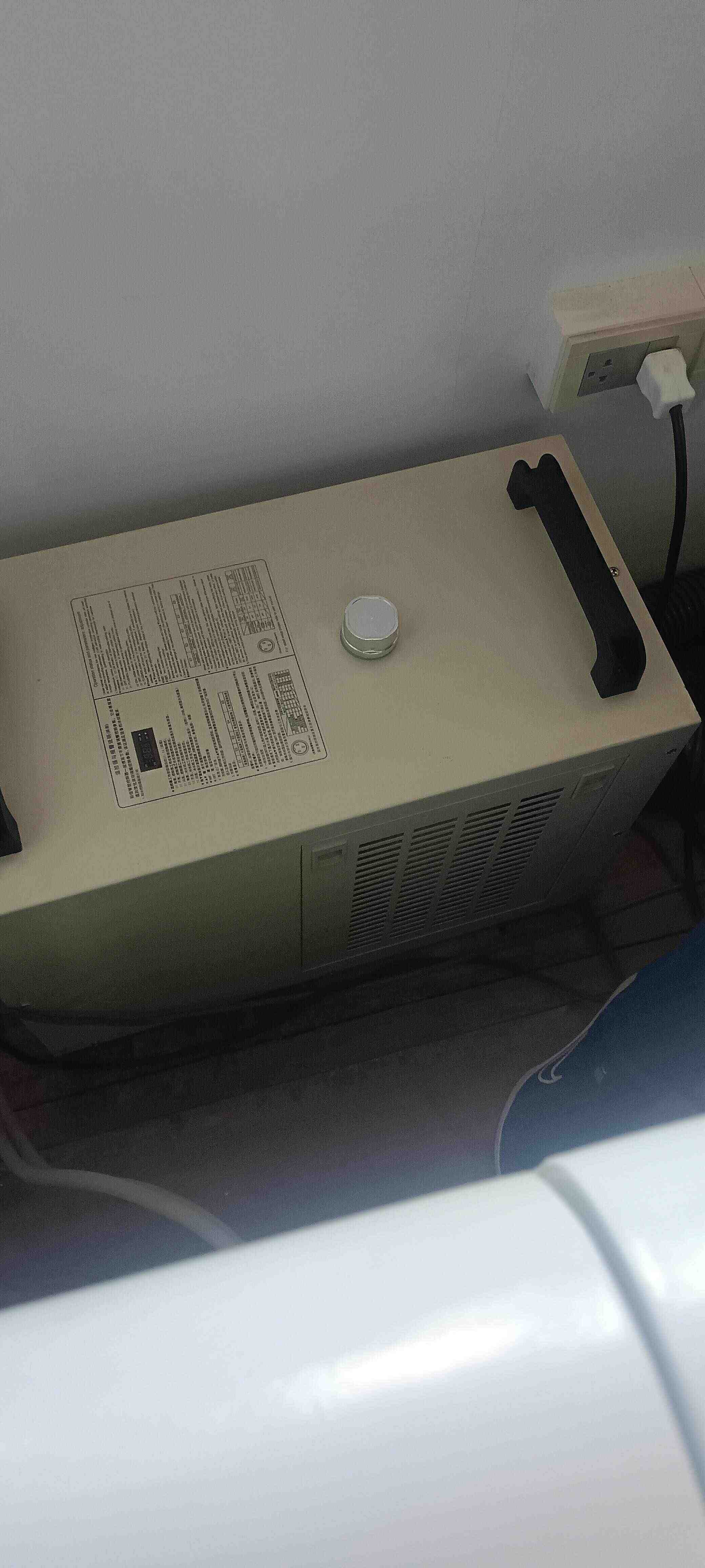
- turning on the Chiller for the laser cutter.
- turning on the other extractor that is inside of the laser cutter.
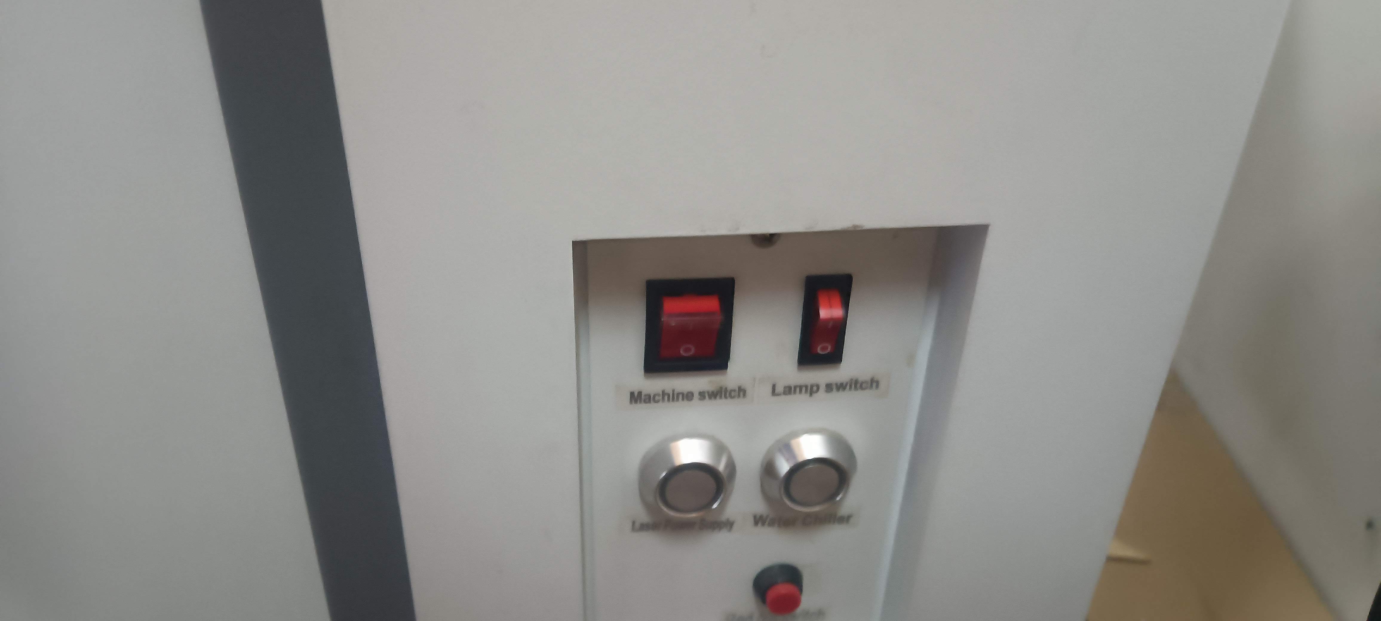
- having all these turned on these buttons shown here should be on and also you need to switch the machine on and the lights off the machine also on.
- when the machine is turned on it always goes to its origin for calibration and then to the last origin that was saved.
- you always need to have the door closed when the laser is working.
- The program is called Power cut and when you open it in the computer it is going to make the sound that is letting you know that it was connected to the machine.
- these machine can cut off to 6 mm, is a CO2 laser so there are some materials that we cannot cut in it
- when you put your material inside of the machine you have to use a little cube that helps you calibrate it so the laser is focused on top of your material
- now regarding the processes that it can do it can do, cutting and Engraving
- when you are doing a cut process you need to look into the power and speed that allows you to cut the material
- when you are doing an engraving process you need to also put those two parameters set before and also an engraving step.
- you can know these parameters by doing tests of speed and power like we did here
- After you are done designing and preparing all of your processes with the program (by putting each layer with a color and taking into account the order of the work), you need to send it to the machine.
- when the design is already on the machine you have to use the frame button to know how much of a space it's going to take and also a fixed button to allow you to have an origin that you decide where it is
- every time you are moving your laser to a point where you decide you want to be the start of your work and the origin of your work you have to use the fixed button
- After you do all of that press the start button and let the laser do the work.
Parametric design
Now regarding the parametric design I wasn't sure what to do for this week because I didn't want to do something like the shapes that everybody does, maybe I should have done that but oh well I already didn’t.
My first idea was to do some kind of tree but I only drew some little designs of it I ended up not liking.
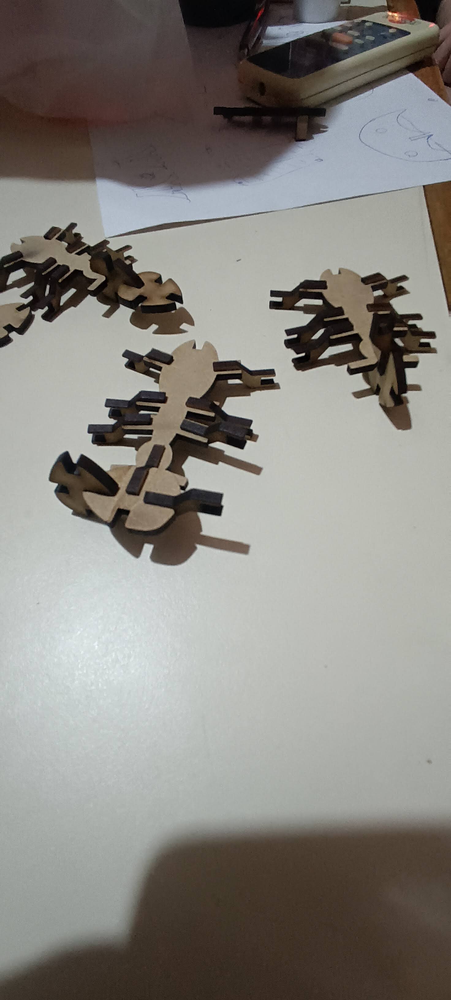
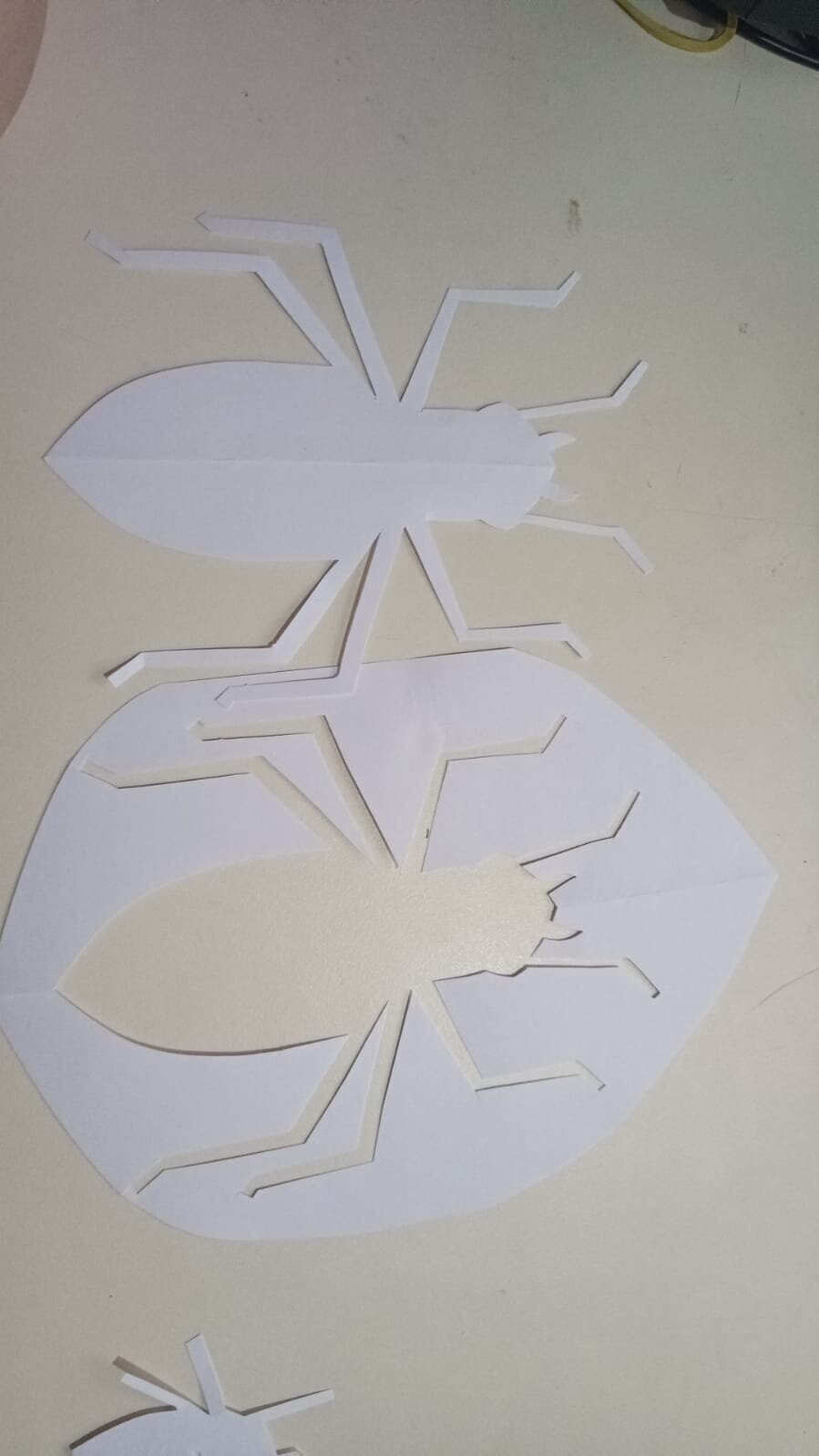
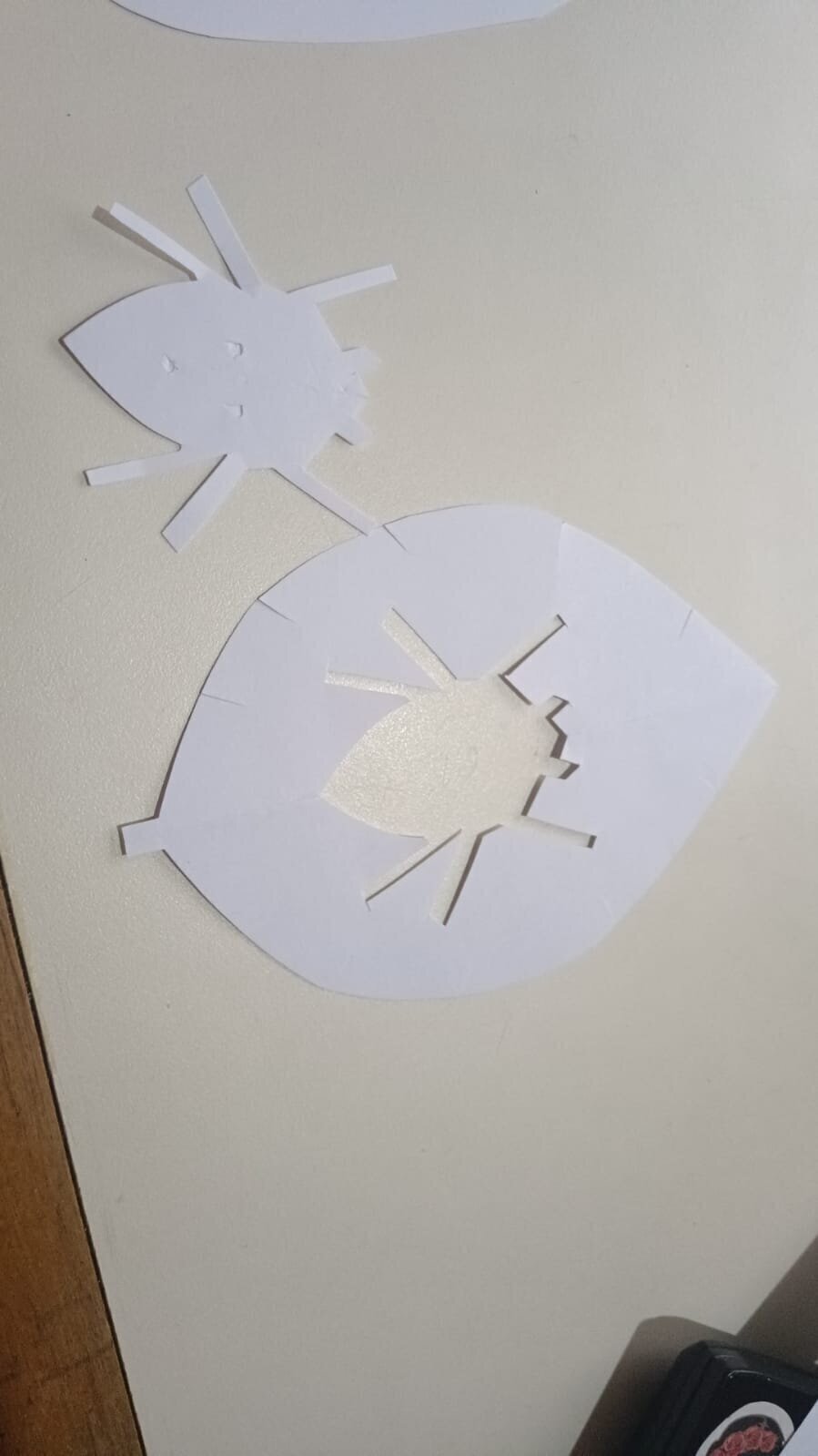
After that I went to school and asked the art teacher for some ideas and he told me about these little ants that usually make bridges with their bodies and I liked that very much. So I tried to design a little ant that could be like these ones.
Together, we made some first prototyping of this little dudes:
I wanted to design it from scratch so I could test my skills with fusion and also my parameterization skills. I knew that I had to use the kerf with the design and I decided to use the MDF as my base.
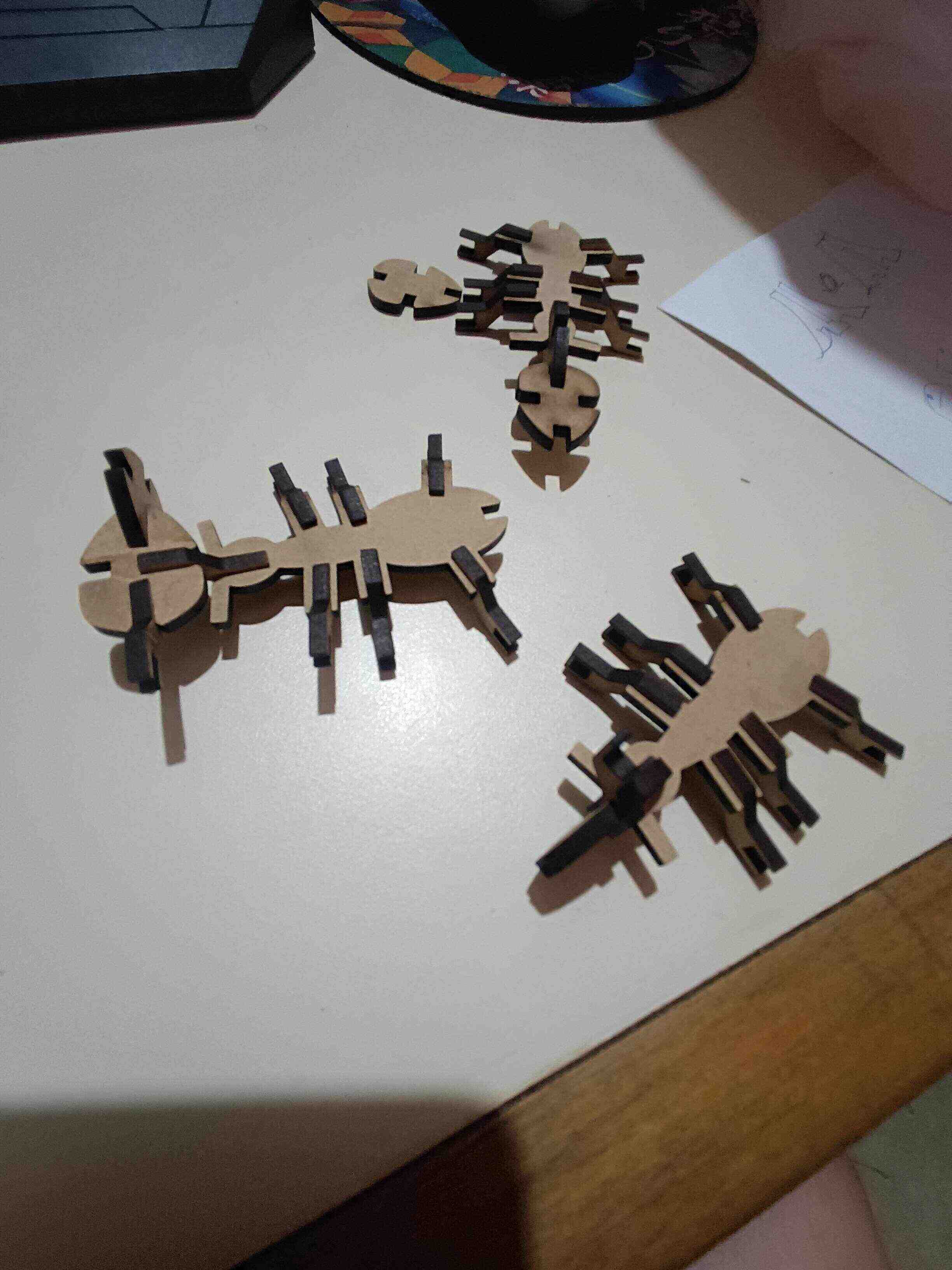
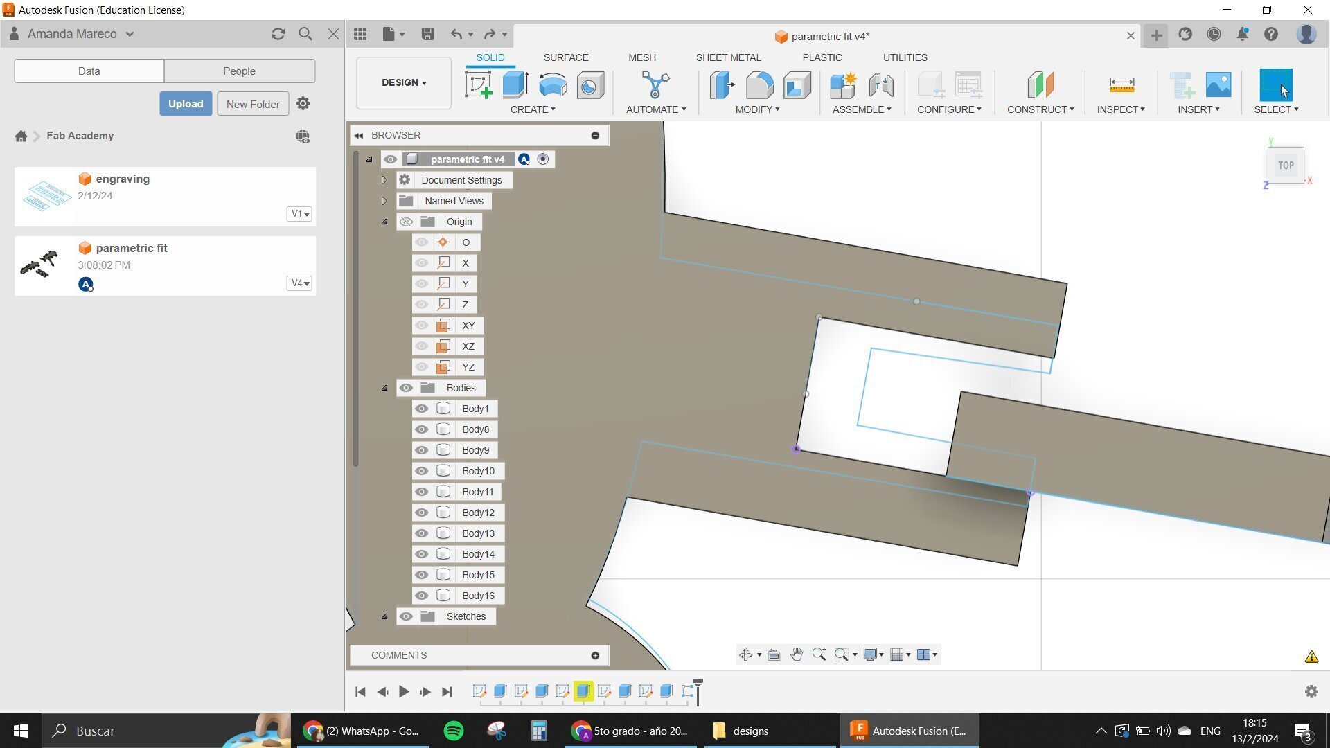
I started with one design where the ant looked a little boxy and had some holes in their legs so we could actually put some extensions on it for it to be standing up.
I didn't like the first design that much so I started to think about giving it an angle leg that could be connected to the body and also to other bodies in the feet.
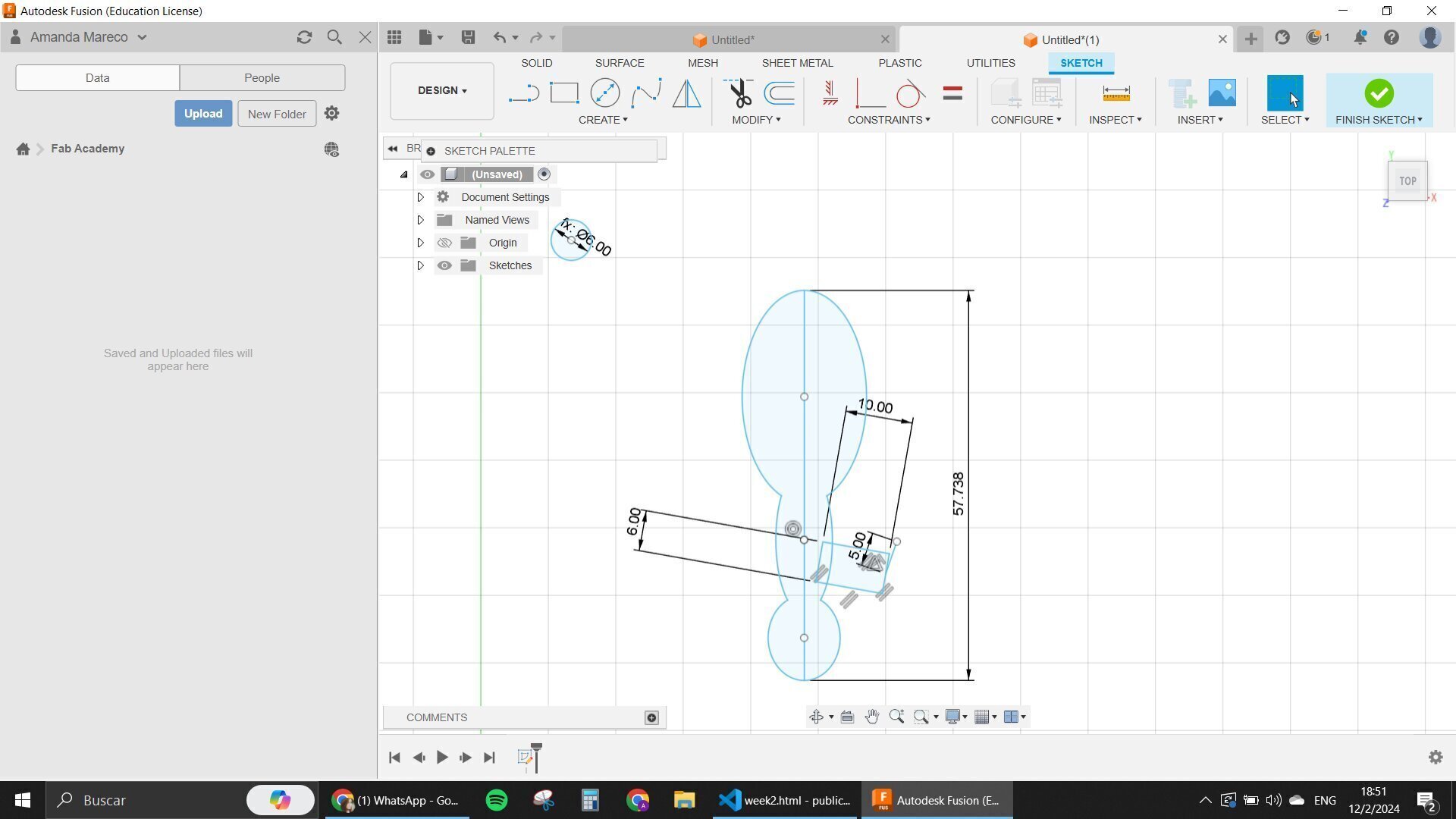
Before that though I started to design the little leaf that would be the one that helps the ants to be connected between themselves. I put some indentations in four parts of it so it can give me some dimensions to work with.
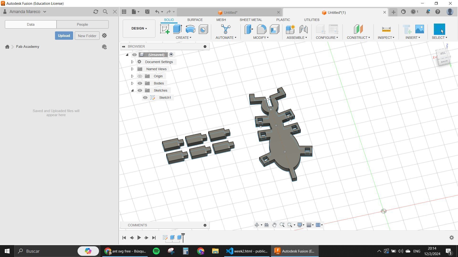
Then I designed the other ant that I wanted. The angled legs at first were very long and I didn't like them again, so I changed them to some smaller ones.
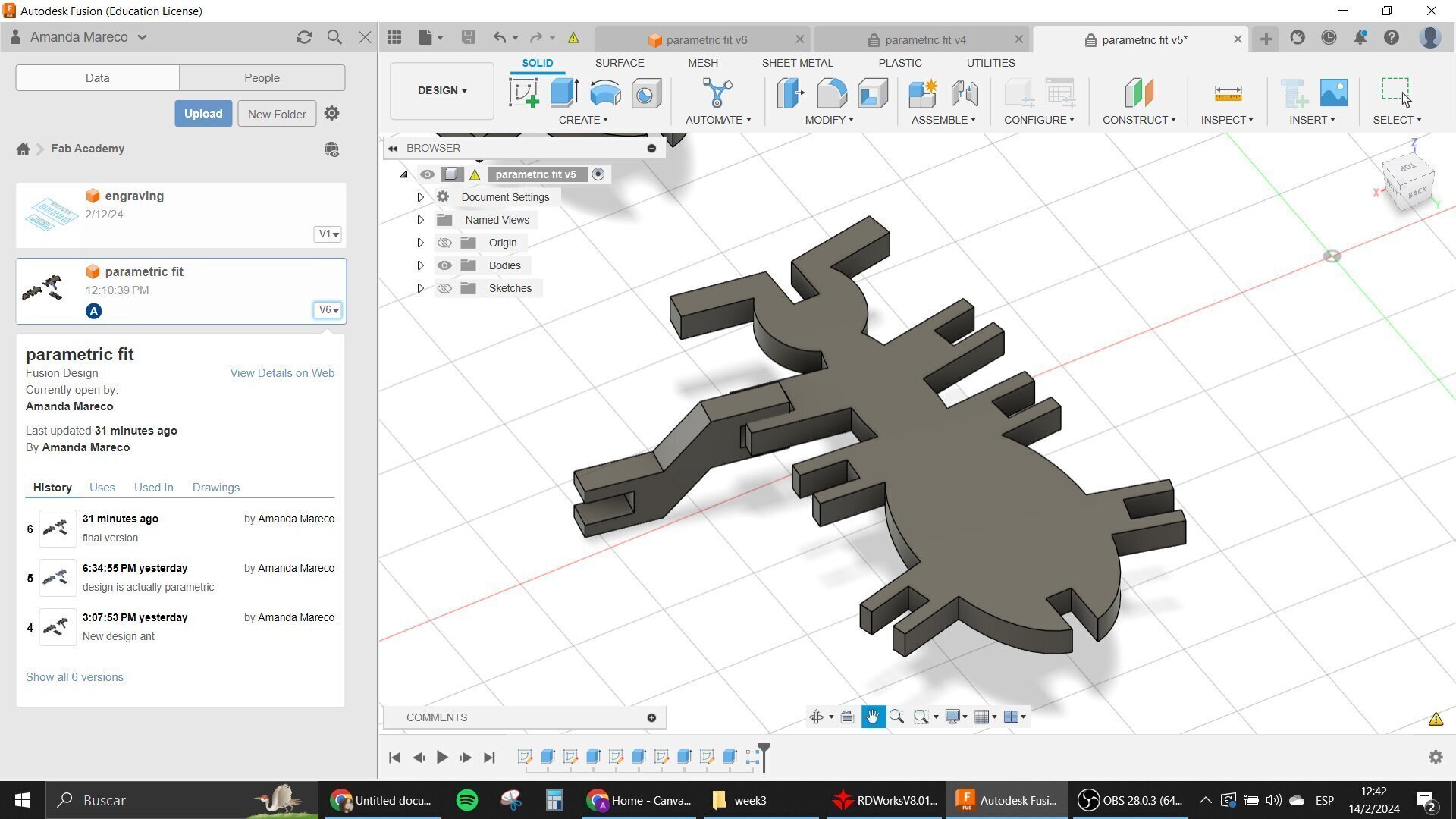
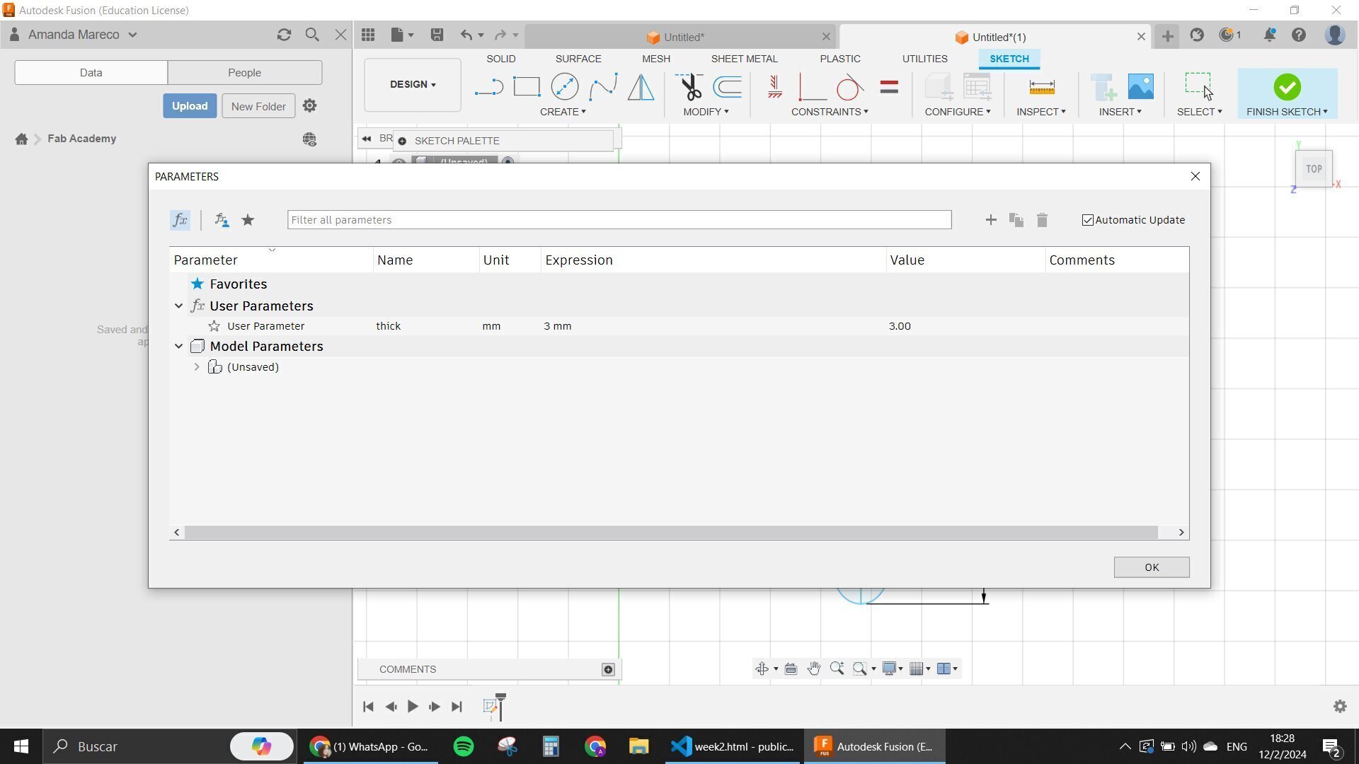
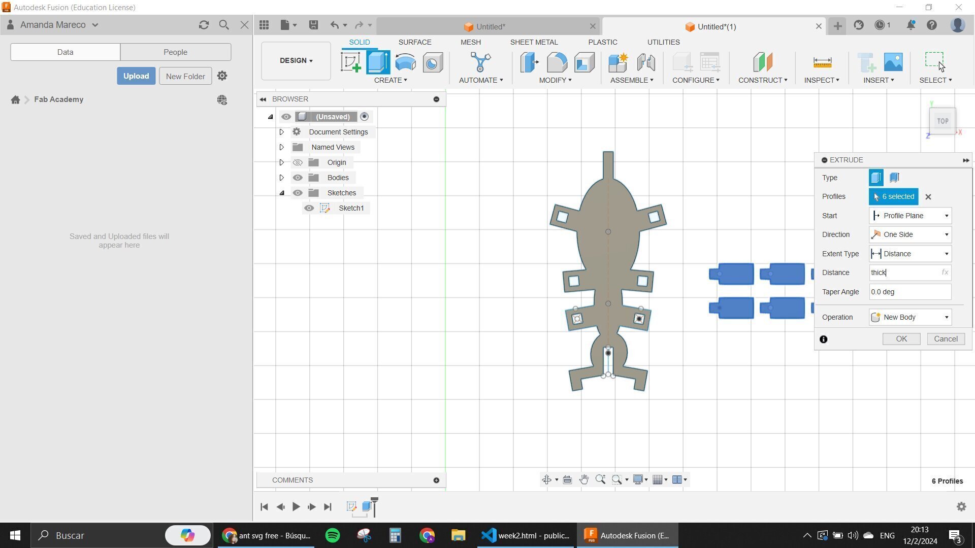
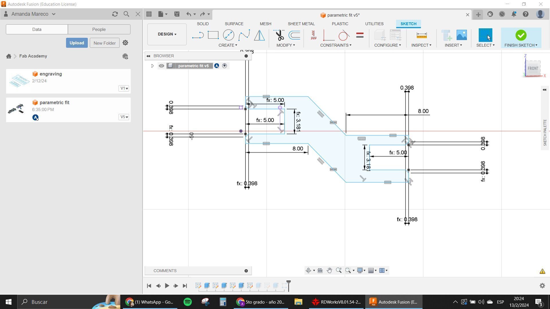
After finishing up with these I try to see if my design was parametric, btw all the time when designing I was putting formulas in the indent and faces where the connections would be, taking into account the kerf.
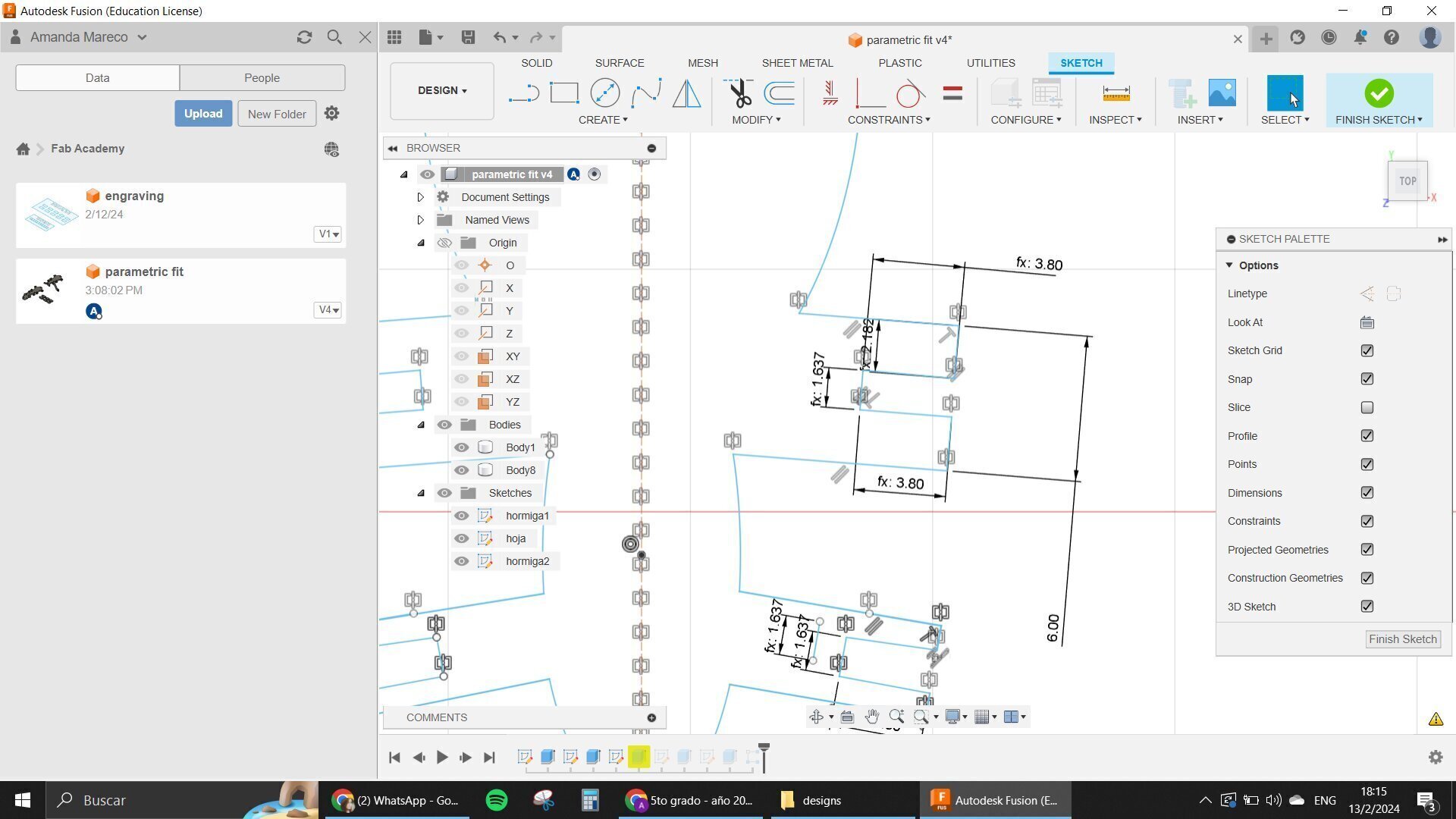
The problem was that when I changed the parameters the ant basically exploded, so I had to do changes for it to work like I wanted it to.
The problem was that I didn't put some constraints in some parts of the design that made it actually be disconnected when the parameters were changed.
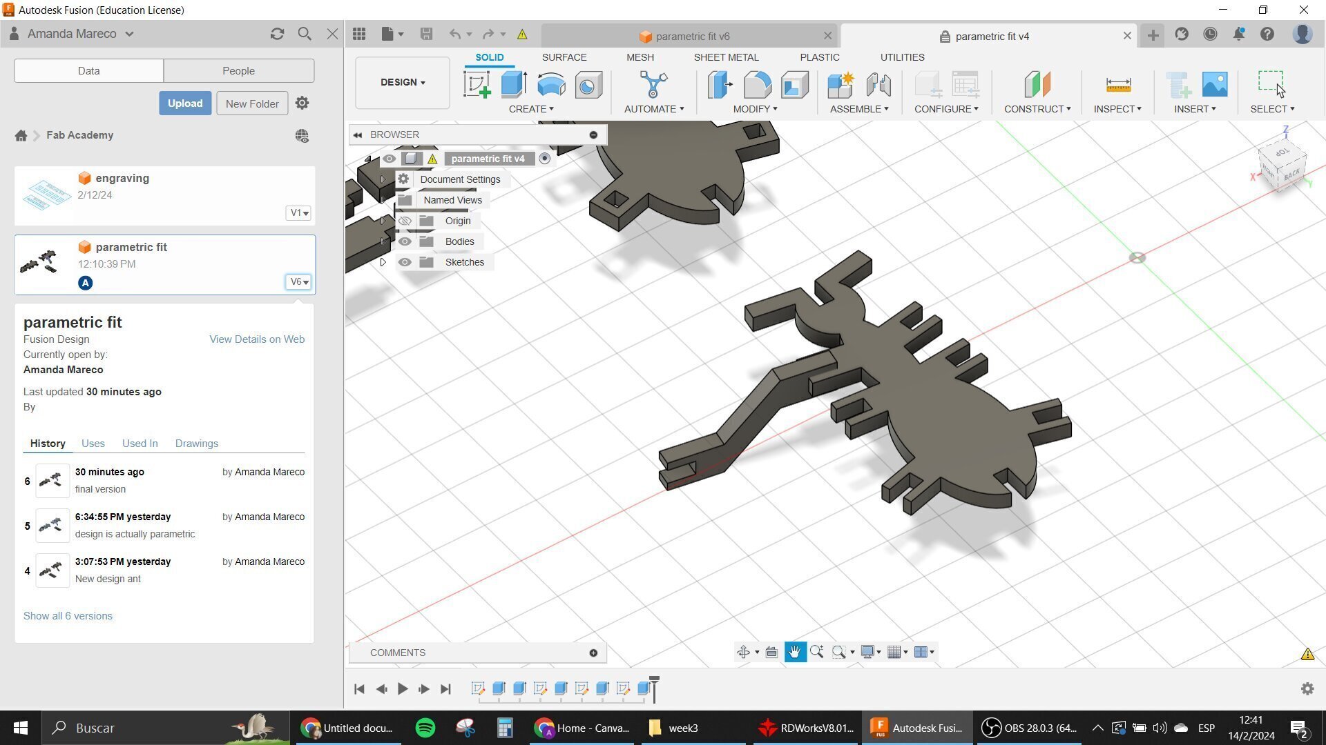
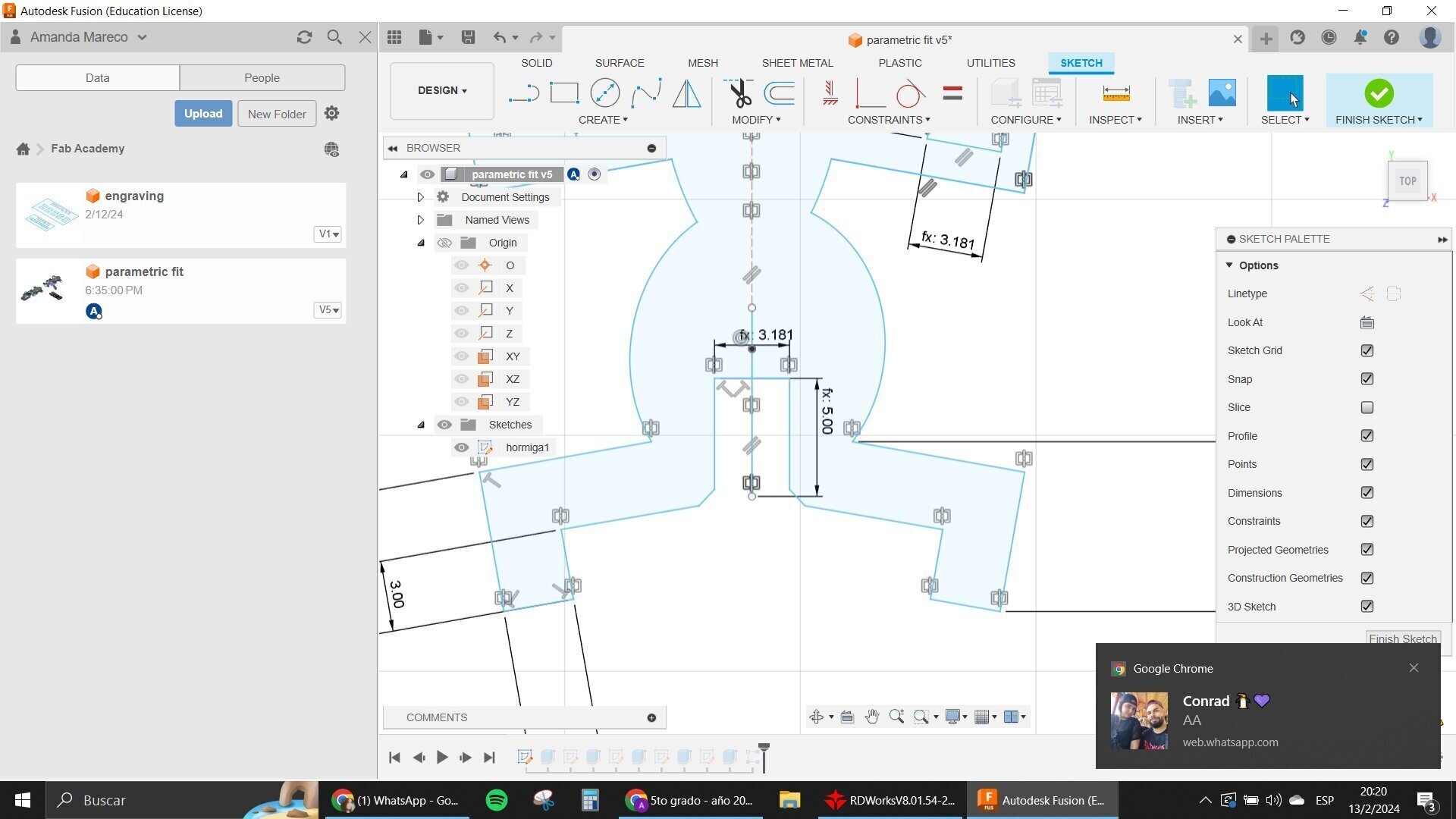
This took me a very long time to figure out but I found all of the places where the parameters were causing problems like some unions that weren't really connected and so on.
I used the Coincident constraint very very much, as well as the mirroring constraint and parallel constraint.
One advice that I could give is to try not to work with Ellipses in Fusion. They are really complicated and glitchy.
When I finally had my ant ready and it was parametric like I needed it for the assignment, I tried to export it in DXF to cut it in the program of the laser cutter.
My problem here was that when I went there and opened my Ant, the program basically decided to ruin the whole thing because it wasn't working like it had to.
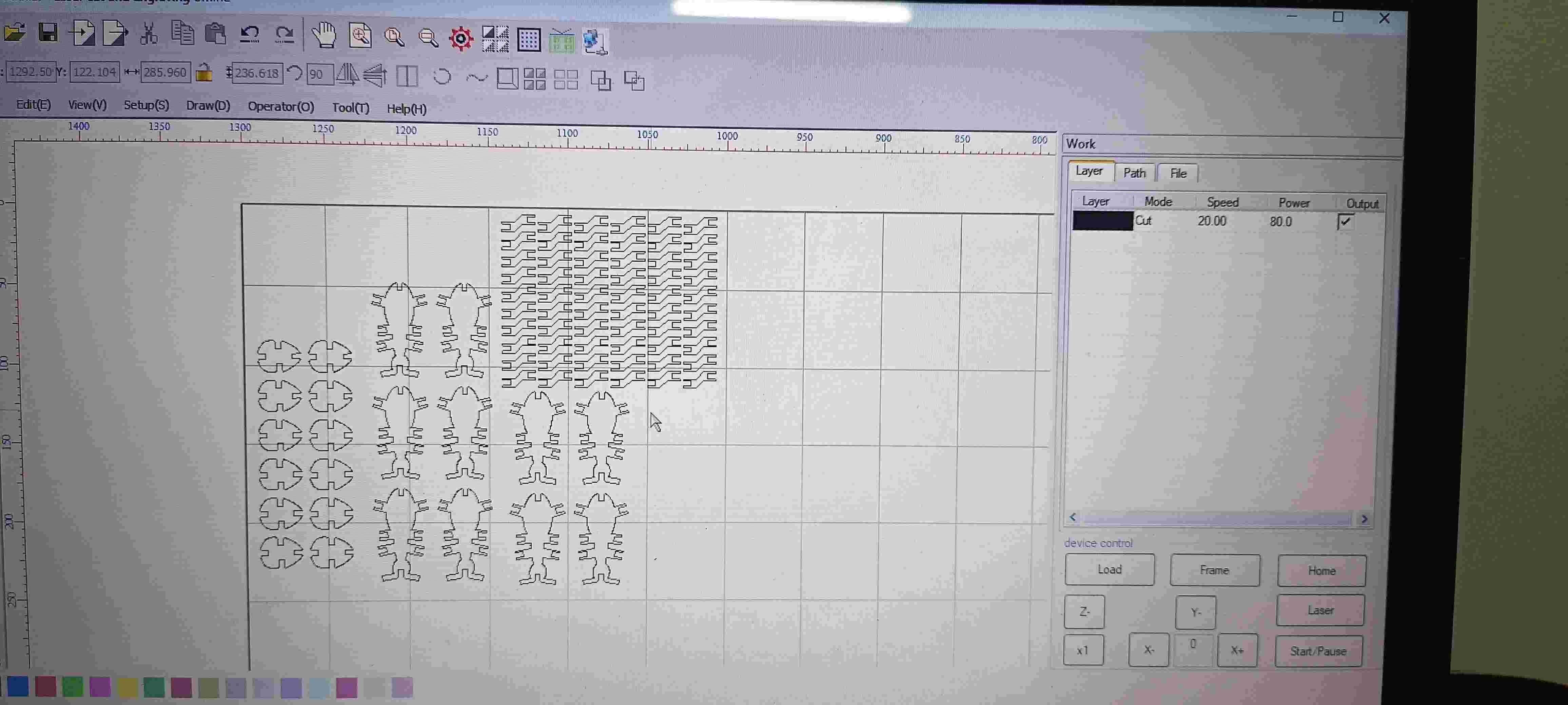
A solution that I found was to try to open it in RDWorks which allowed me to export it in .ai which was a format that Power Cut also supported, so basically I tried to clean up my design in Rd Works before cutting it with the laser.
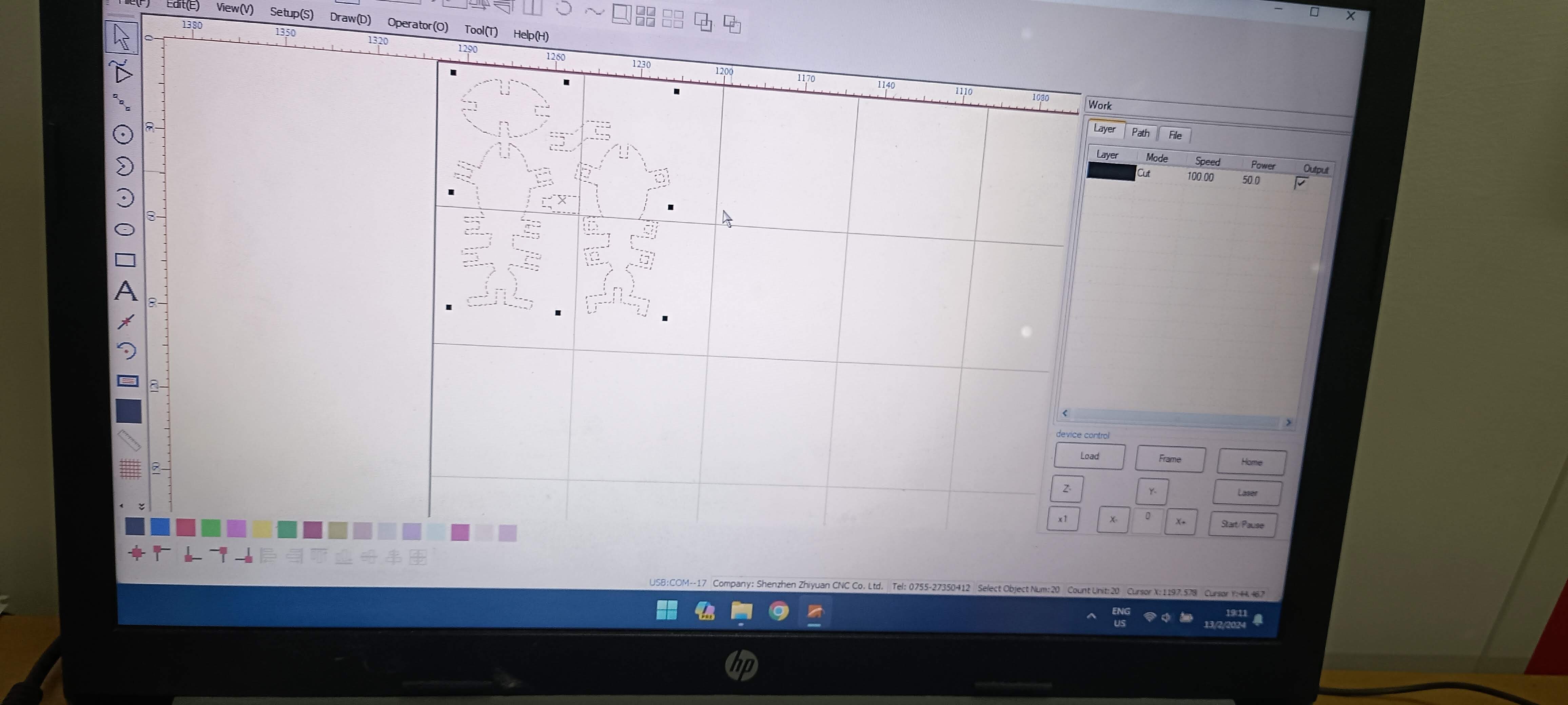
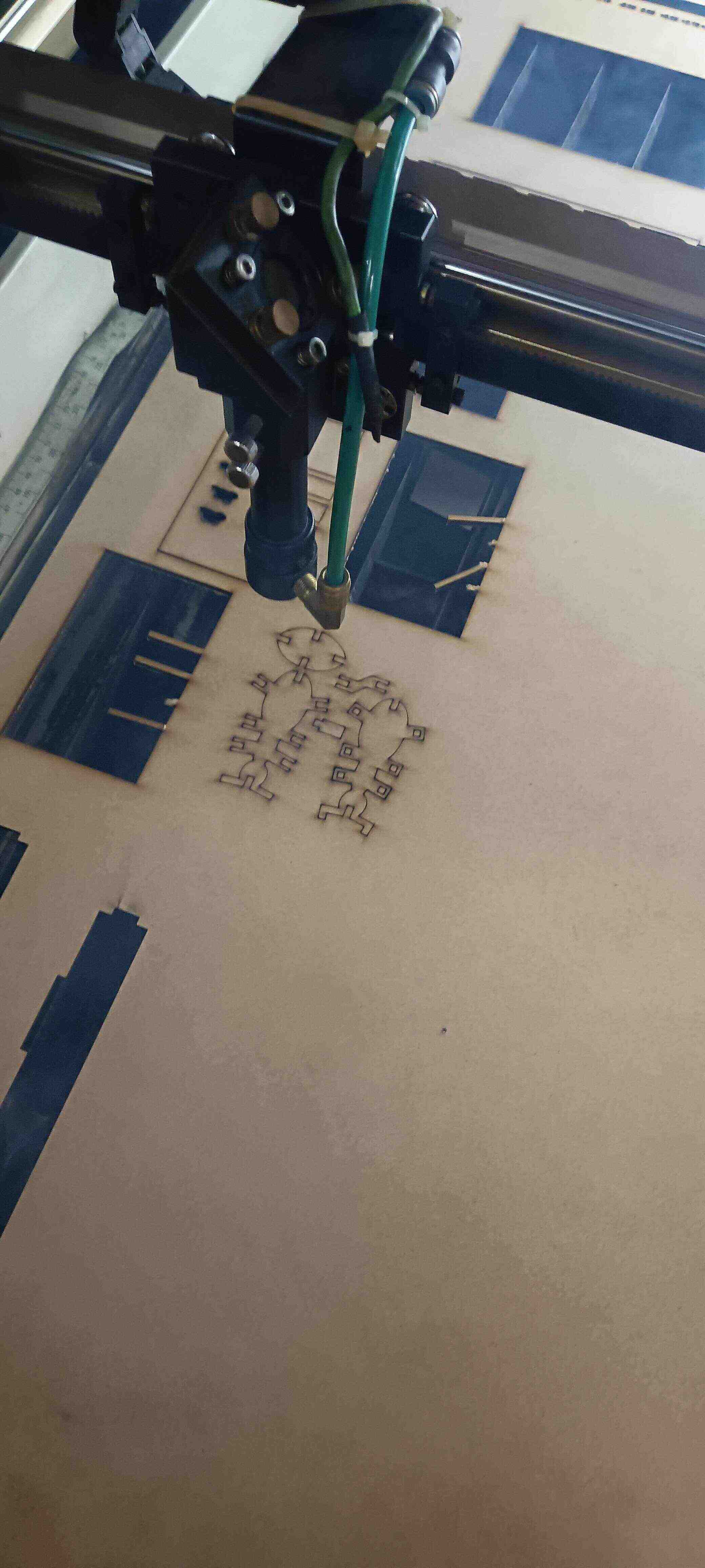
After doing a first test that I could finally cut after many many trials and tribulations I realized that my formula for the kerf was actually making the design be a little too tight so I changed my design a little bit for it to be more loose I also added chamfers.
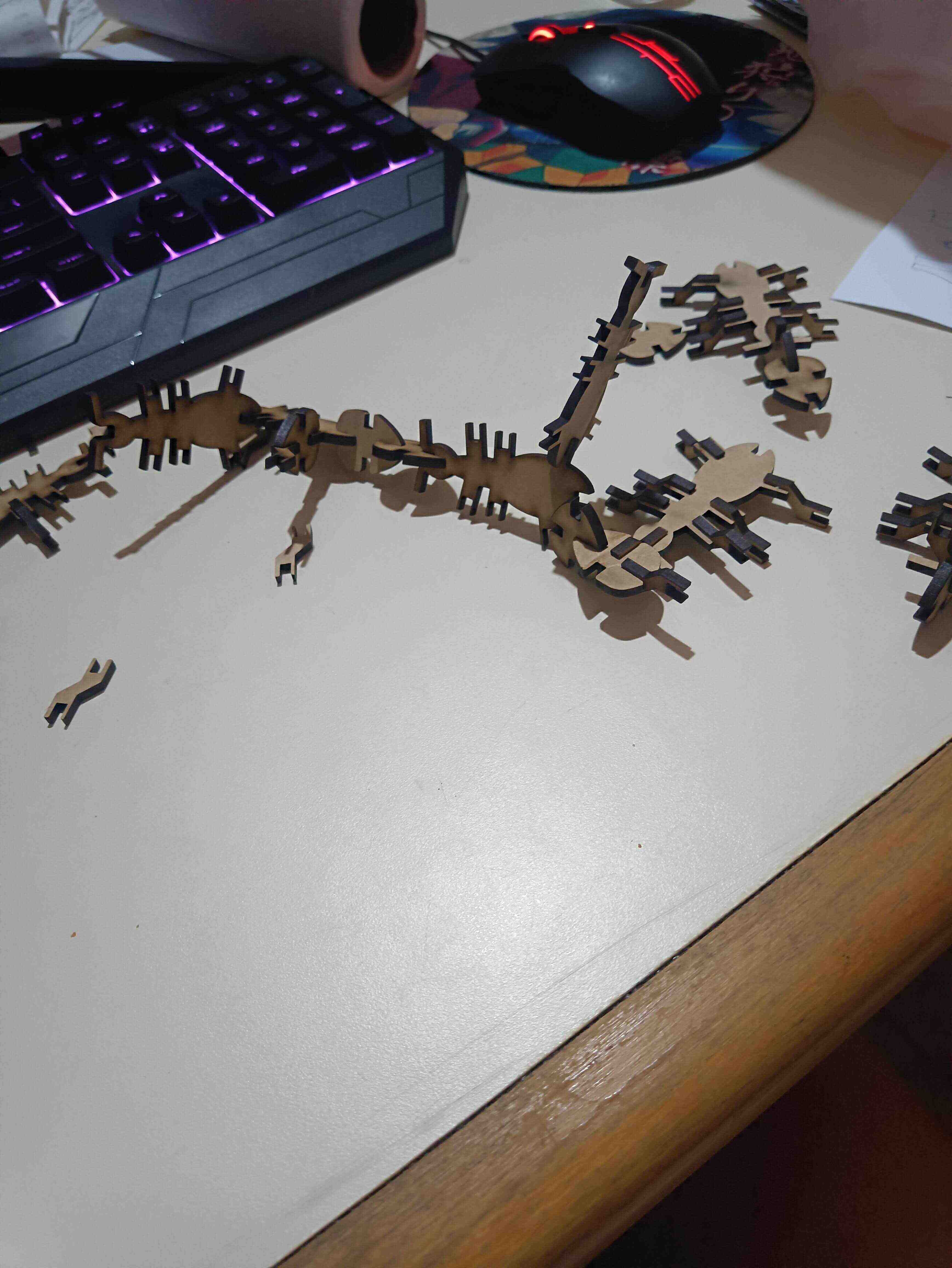
With that changed I tested it one more time and went for my second design of the end to make my colony.
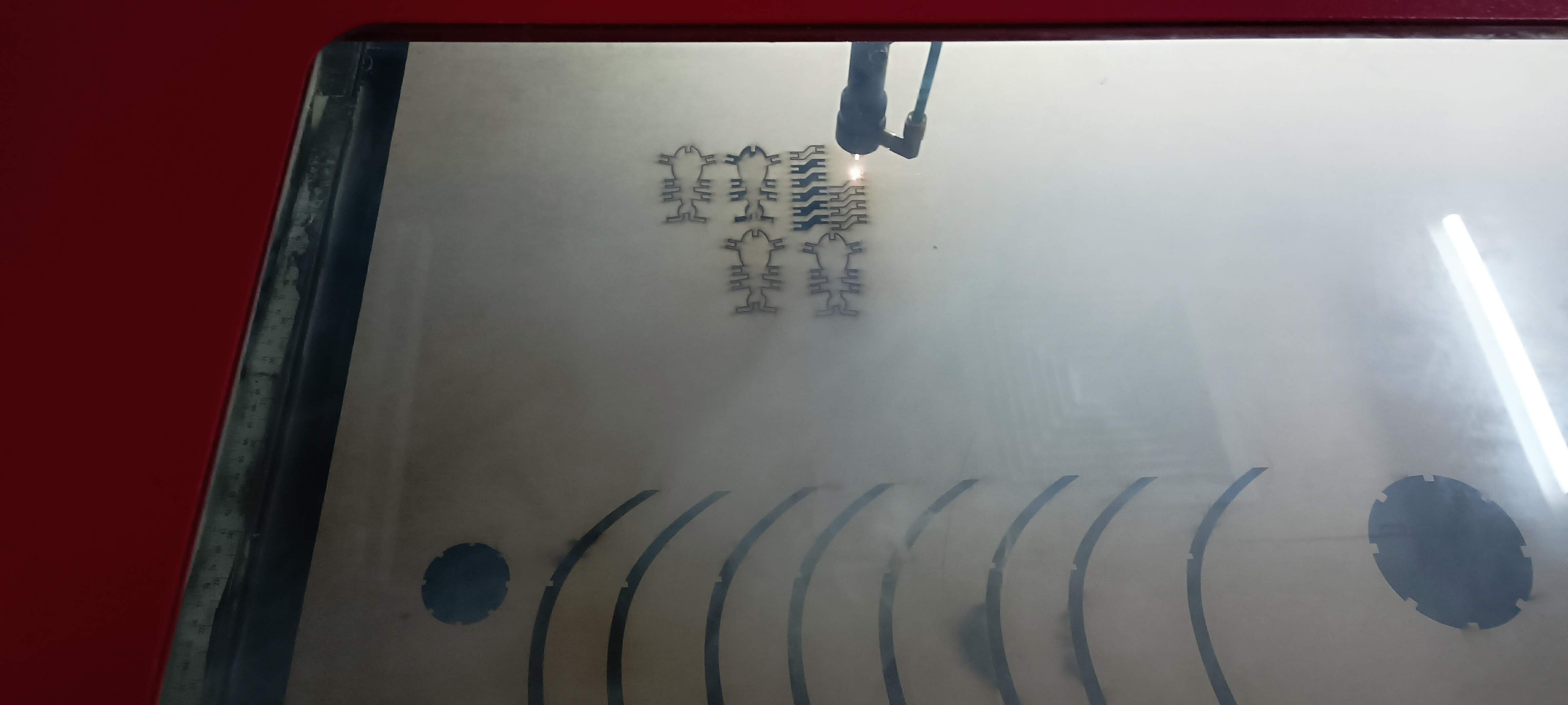
and here is how it went.