Week 9: Output Devices
-
Group assignment:
-
Measure the power consumption of an output device.
-
Document your work on the group work page and reflect on your individual page what you learned.
-
-
Individual assignment:
-
Add an output device to a microcontroller board you’ve designed and program it to do something.
-
In this assignment I tried to use my own Mandy Xiao board to try and test some programs that will allow me to control some output devices that I want to use in my final project.
Navigation
Reviewing the Display
I want to use a little TFT OLED with its touch functions called the ili9341. This is a little screen with the following general specs:
(info taken from the datasheet)
-
Display resolution: [240xRGB](H) x 320(V)
-
Output:
-
720 source outputs
-
320 gate outputs
-
Common electrode output (VCOM)
-
-
a-TFT LCD driver with on-chip full display RAM: 172,800 bytes
-
System Interface
-
8-bits, 9-bits, 16-bits, 18-bits interface with 8080Ⅰ /8080- Ⅱ series MCU
-
6-bits, 16-bits, 18-bits RGB interface with graphic controller
-
3-line / 4-line serial interface
-
-
Display mode:
-
Full color mode (Idle mode OFF): 262K-color (selectable color depth mode by software)
-
Reduce color mode (Idle mode ON): 8-color
-
-
Power saving mode:
-
Sleep mode
-
Deep standby mode
-
-
On chip functions:
-
VCOM generator and adjustment
-
Timing generator
-
Oscillator
-
DC/DC converter
-
Line/frame inversion
-
1 preset Gamma curve with separate RGB Gamma correction
-
-
Content Adaptive Brightness Control
-
MTP (3 times):
-
8-bits for ID1, ID2, ID3
-
7-bits for VCOM adjustment
-
-
Low -power consumption architecture
-
Low operating power supplies:
-
VDDI = 1.65V ~ 3.3V (logic)
-
VCI = 2.5V ~ 3.3V (analog)
-
-
-
LCD Voltage drive:
-
Source/VCOM power supply voltage
-
AVDD - GND = 4.5V ~ 5.5V
-
VCL - GND = -2.0V ~ -3.0V
-
-
Gate driver output voltage
-
VGH - GND = 10.0V ~ 20.0V
-
VGL - GND = -5.0V ~ -15.0V
-
VGH - VGL 3 ≦ 2V
-
-
VCOM driver output voltage
-
VCOMH = 3.0V ~ (AVDD – 0.5)V
-
VCOML = (VCL+0.5)V ~ 0V
-
VCOMH - VCOML ≦ 6.0V
-
-
-
Operate temperature range: -40 ℃ to 85 ℃
-
a-Si TFT LCD storage capacitor : Cst on Common structure only
Using the TFT Display
For this week I followed many tutorials and tested things also with chatGPT.
First thing was trying to install the libraries that were needed for the Display to work properly. And also connect the display to the XIAO.
The tutorial that I found on how to use it with Raspberry had a library compatible with the RP2040 architecture. So I decided to test if it was working the same with the XIAO as it did with the Pico.
I copied the code of the library and pasted it in Thonny and saved it inside the XIAO with the proper name.
Now regarding the connection, like I already said, I used the Mandy Xiao developed in the last assignment that had an SPI connection prepared for this OLED to work. I followed the names of each pin from the display and with my diagram of the Mandy Xiao connected all the things.
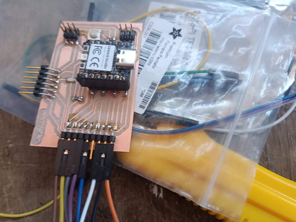
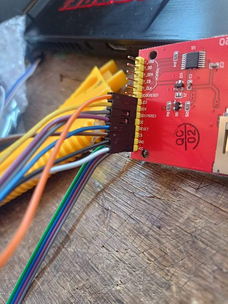
Then I went on with the examples. The first one that I followed was a very simple one where you could see the colors.
Here you can see the original code copied from the tutorial

I went on and tried to put the pins that were dedicated to my SPI and my display settings for the XIAO. Put the code with this new number of pins in the “spi” and “display” variables that are seen here. When I wanted to test it, the Thonny sent an error saying that I had a “bad sck pin”.
Here is where I went back to ChatGPT to try and understand what happened. I fed the code and the problem with the error, and basically I forgot to change the “channel” of my SPI communication. As you can see in the picture, the code says it is channel 1, which is nonexistent in the XIAO. So I had to change that to 0.
After that change, the code worked!
Video colors working
-
Animation Example
After that, I went on with another example that showed a little animation of some polygons appearing on the screen in a sequence. I copied the code and went on with the small changes of the pins for my board like I did before. This one as it was, also was missing something, and sent me an error.
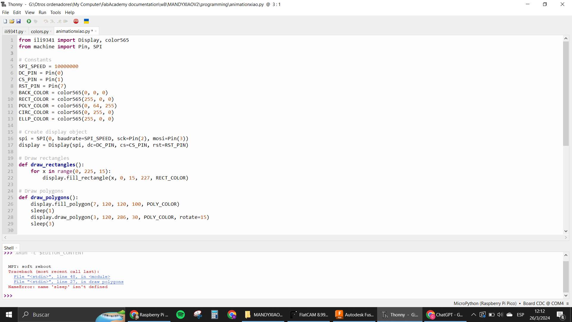
Thankfully this one was an easy fix, as I soon realized that the code in the page was missing the import of the Time library. I added that to fix the mistake.
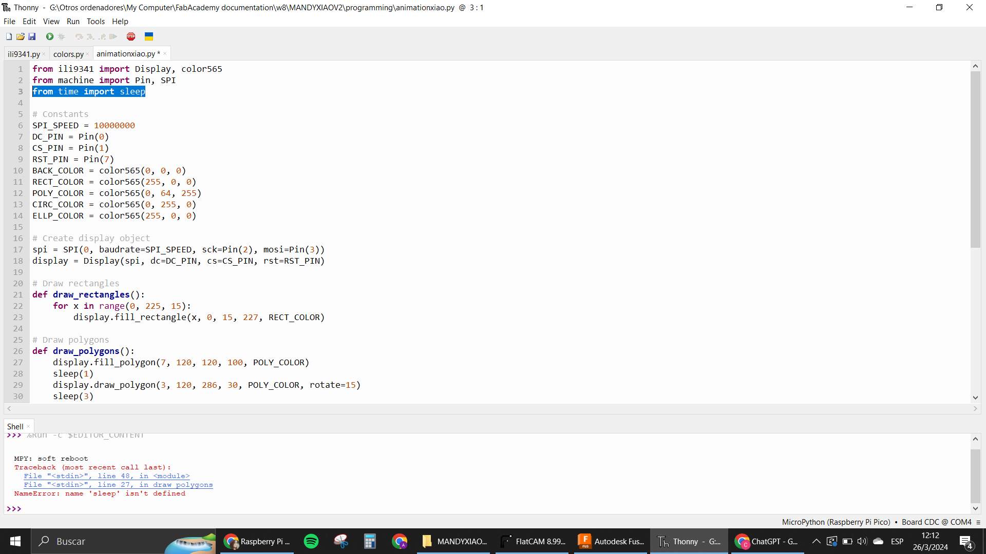
The code basically created a series of functions with each of the polygons that would be seen in the screen, and had some variables with the colors in RGB code saved.
Video animations
-
Bouncing Boxes Example
Next one was the bouncing boxes example. All the same process and this one was smoother because I was starting to understand how the library worked.
Here is the video of my test.
Video bouncing boxes
-
Text usage in Display
After that I wanted to also test how to work with texts on the display. Since the tutorial I was following didn’t cover this part, I looked for a different one and also asked ChatGPT to help me with this. At first I tried installing all the libraries and types of fonts that were shown in a page inside the tutorial.
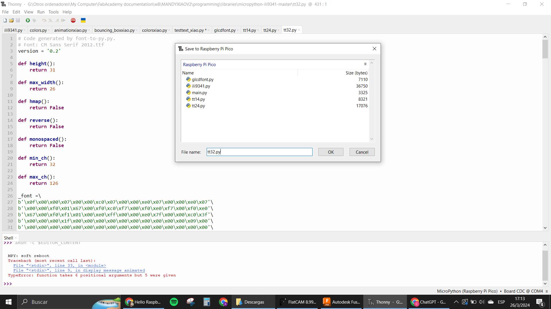
But it didn’t seem to work out cause the library supposed to work with these already made fonts couldn’t really read them. The library was deprecated, so I went for another one called xglcd_font, which was what ChatGPT was asking of me anyway. Apparently the code that was needed for the type of font was a font.c one for this library. I looked for that as well and saved it in a folder in my XIAO with the name fonts. I had many trials with no luck. I couldn’t understand the error because it said something like “AttributeError: 'int' object has no attribute 'get_letter'” in the error message, inside the display_message_animated function that ChatGPT helped me build. I of course went back and asked, many solutions were suggested but it was in my power to go through them. My first instinct was that the library had some issues, cause it had happened before. So I went and looked inside the part where the draw_text function from the library was called. There I realized that the problem was the order in which I had given my attributes for the function. I was giving the color of the font first and the font file after, but in reality it had to be the other way around for the function to work properly.
This fixed the problem finally and I could see the text on my screen.
Here is everything that ChatGPT helped me with in this section.
The only issue was that the message was too long for the size of the screen, so I had to think in a way to make it so that when the letters reached the end of the screen, they would go directly to the next line.
This I did with a little math and logic operation that I tried to implement to help me move the positioning of the cursor that was writing. The x coordinate has to be smaller than the size of the screen, and if it is bigger, the y position of the cursor needs to change and the x has to go back to the beginning of the coordinates. Here you can see the little change I made to the code in the “display_message_animated” function:
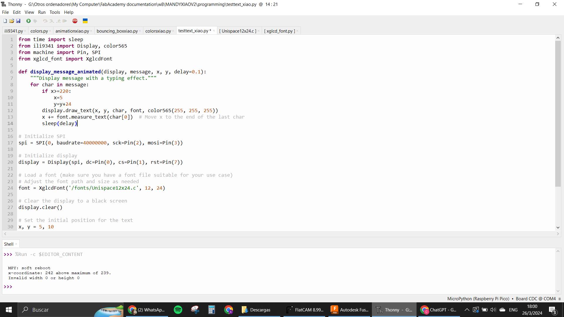
After that, my code worked.
Video of the working text
More tests need to be done to see what else can be done with the screen, like if it can just repeat what the computer is showing or if it is possible to create a user interface in it.
Using a servo thanks to ChatGPT.
Lastly, I tried connecting a servo to one of the General Purpose sections I made in my Mandy Xiao. I used this one called HK-15138
I connected the little servo knowing that this board will only allow me to work with one servo at a time because of the voltage and amp consumption needed for these types of outputs to work out. For a next version I’ll probably make some kind of voltage adapter that will go into the board that will allow me to have a different power source for outputs that need more energy to work.
For the coding. I continued working with my loyal friend ChatGPT and tested if the code it was suggesting worked. It was smooth and made the servo work pretty well. Most likely the section where the duty cycle for the PWM is made is something that will have to be adjusted depending on each servo used, and also the frequency can be tested by looking at each of the servos used datasheets.
Here is the chat with the gpt for this.
And here is the video of the servo working 😀
Groupal Assignment
-
Measure the power consumption of an output device.
In this week's assignment we have to basically learn how to measure the power consumption of any output device. This can be done using a multimeter, by using it to measure the output voltage consumption, and also the current that it draws when it is turned on.
By doing that, you can have the data to use the formula for Power.
P = Volt x Amp
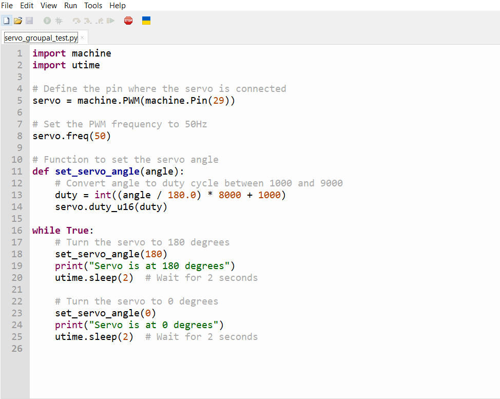
For this, we decided to use the “Mandy Xiao” with a servo motor connected to one of the GPIOs already reserved for that and have a very simple program that will help us turn the motor 180° and also go back to 0°.
We decided to use the MicroPython environment to program this in a very easy way, using the PWM, we create a function that reads the angle, and sends it to the PWM using the “duty” calculated with how the analog read works.
Here a picture of the program:
With the program ready, we finally could start measuring the desired magnitudes, and using the multimeter in the voltage and putting the probes in parallel with the circuit, we get this lecture:
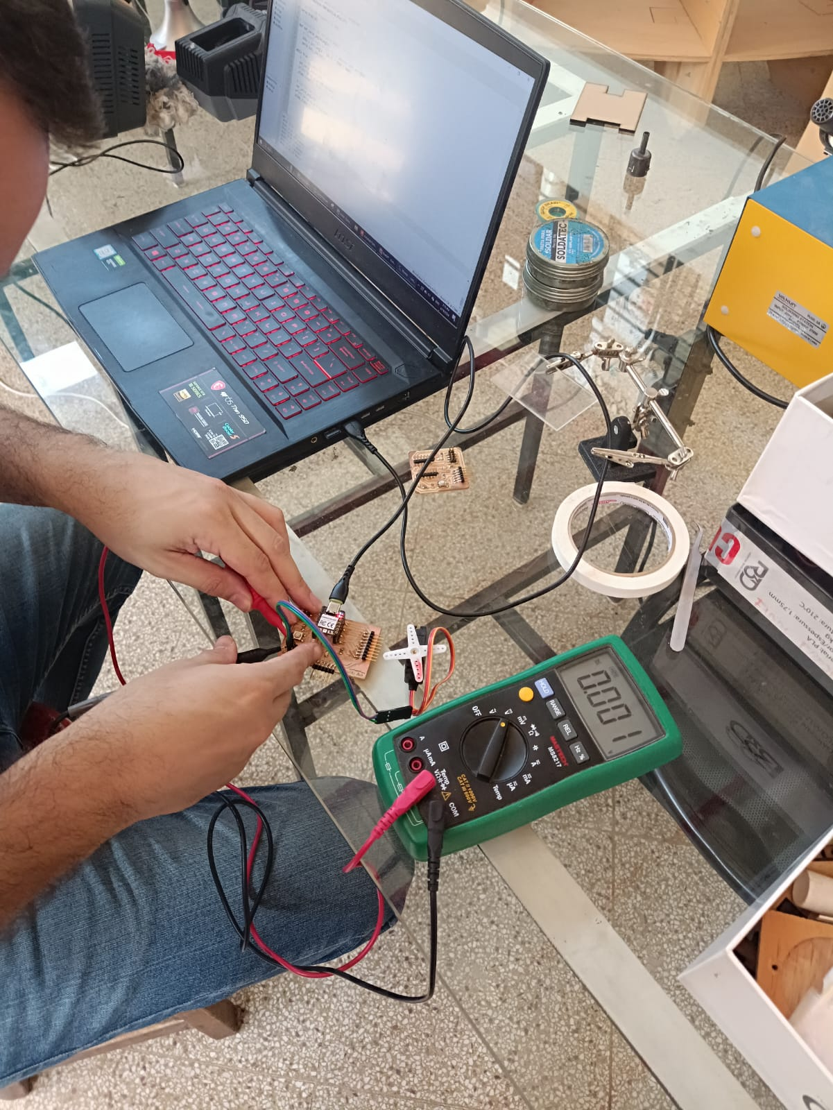
We got 0.42V when the motor turns to 180° and 0V when it is in 0°.
After having that value, we proceed to change the probes of place, to measure the current that flows through the circuit in that moment. And we get this:
We notice that the value changes but its peak is the one shown in the picture above. So we use this value as it’s the most current the circuit has to endure. The value is in micros so this has to be adjusted when the 30,7 is used in the formula.
Using this two we get this:
P = Volt x Amp
P = 0.42 (30.7)-6
P = 50.1pW
So, we can conclude, that the circuit only draws a power consumption of 50.1pW.