Mechanical Design, Machine Design
-
Group assignment:
-
Design a machine that includes mechanism + actuation + automation + application
-
Build the mechanical parts and operate it manually
-
Actuate and automate your machine
-
Document the group project
-
-
Individual assignment:
-
Document your individual contribution
-
Creating Esperancita
For this machine week we decided to build a t-shirt folding machine, after having a long time of discussion about what we wanted to make.
After that, we had to distribute the work and start to think how to build it, so we looked at some examples to help us out, and saw one that we liked.
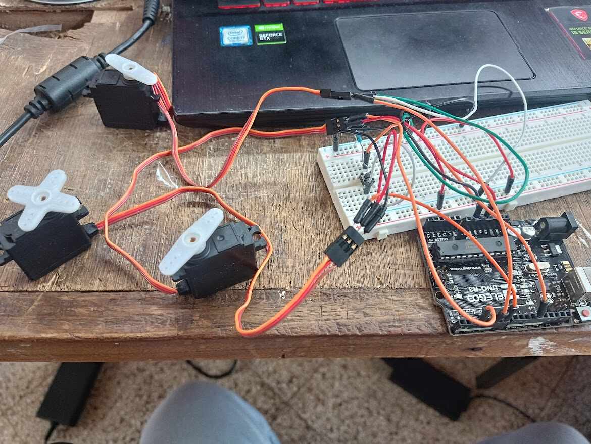
We wanted to make at least the folding part with 3 servomotors controlled by an arduino that were triggered by a button, that was the first iteration of the electronics.
My workflow was to test how the motors would work with the arduino, which we decided to use since it has the 5V that is easier to work with when it is regarding the servos. So I made some tests to see how the connections needed to be done and how the program itself needed to behave, all of them were done in a protoboard for starters just to look how the motors did.
I landed on a program that I liked how it worked. We used this in simulations as will be explained later, and it seemed to be fine, but then, we tested it with the actual mechanism and we found lots of issues.
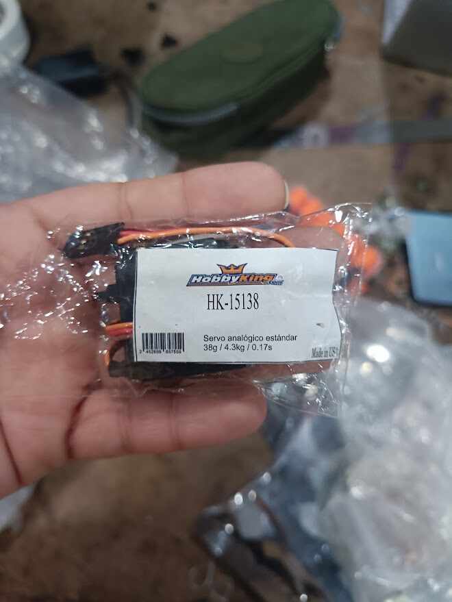
The first one was that the motor couldn’t move the arm. Second one that everything was getting hot quickly. Our first idea was that the motor was actually too small for it, we were using one that worked up until 4kg/cm of force at 4.8V, which seemed like enough but for the configuration of our mechanism for the arm was not enough, at least not while using acrylic like we wanted to.
That is why we tried to find a motor that we thought could help us out, of course, time was not on our side and the only servo motors available at the lab where the ones with “not enough force”, so we had to buy it. Buying servos in Paraguay is a little bit of a complicated task, they are not as available and there is not a big variety to choose from. We saw one that seemed like it could help us out, and we asked in the lab if we could buy to test it out. We went ahead and bought 2 of them, and tested one out, but at the second try we made, it started to make a weird noise.
I know servos are basically motors with a gearbox inside, so I was afraid that the problem was one of the gears moved place or something, but to my demise it was even worse than that, the main gear connected to the outside axle was broken. In the picture, you can see us trying to do something about it, but truly, there was nothing to be done.
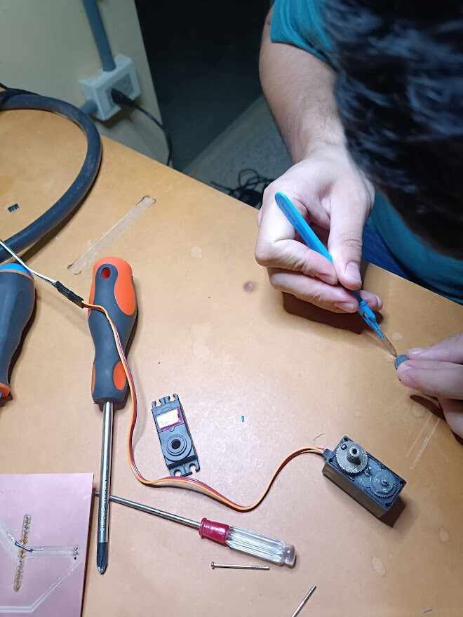
This was pretty frustrating, since according to the datasheet this is supposed to be a metal gearbox servo, and it was sold as such, but in reality, it wasn’t. At this point, we basically decided to change the idea of the acrylic and try to use the servos we already had but move the mechanism a bit so it would help out with the movement. (I am not really a physicist, I can’t truly say how this was actually done, but there is a little guide we used to take into account how far away from the arm the load needed to be and so.
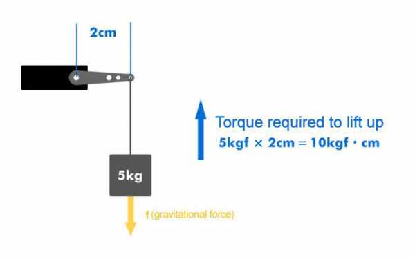
We knew our servo was good for at least 4.8kg/cm so we thought that the closest the load was from where the axle of the movement was, it would work best, and we were right!
After changing the placement of the servo, making it be closer to where the load was supposed to be, it could lift the arm and start folding the clothes so we basically went with that.
Making the PCB:
As I explained earlier, we basically used an Arduino UNO as it was available in the lab and way easier to work with for the voltage thing. I used a little design on TinkerCAD to test the 3 servos configuration with my program as a simulation (I know it is a program intended to be used with kids, but a simulator is a simulator at the end of the day.
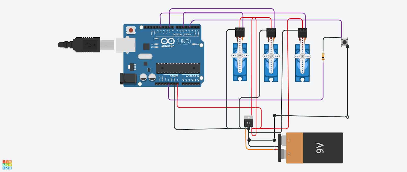
Based on that, I started my design on Fusion and made the Schematics and PCB using the TinkerCAD library as well since it already came with an Arduino footprint and the servos were basically connectors as I needed them to be.
I used a voltage regulator for the first time in a long while, and an SMD at that, and left the Vcc and GND spots to connect it with a transformer we had in the lab that sent at least 1A of output current (which seemed like enough).
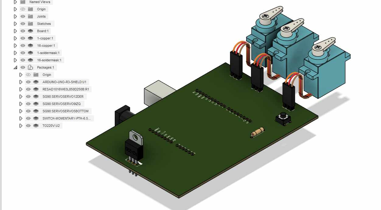
We used a bigger button of course, but with the same principle, a pulse switch that basically turns the sequence of motors on when pressed. I wanted to add more to the whole thing but at the same time I was not sure how to implement different time libraries and they were messing up my initial configuration of the servos (which was pretty important because the positioning of the initial state is decided by the mechanism itself so the motors needed to read that value and save it but it was a bit hard to manipulate in the software for me).
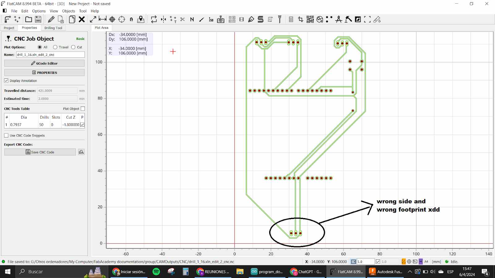
Anyway, the board was made and sadly I didn’t notice an error while placing the components and in my first board I made the mistake of putting the regulator in the wrong layer. Had to make another one and this was a bit time consuming.
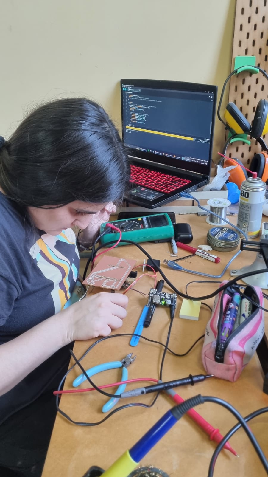
After that, we landed on the final design and we started the tests as explained before. Here a picture of where the circuit was left in the design:
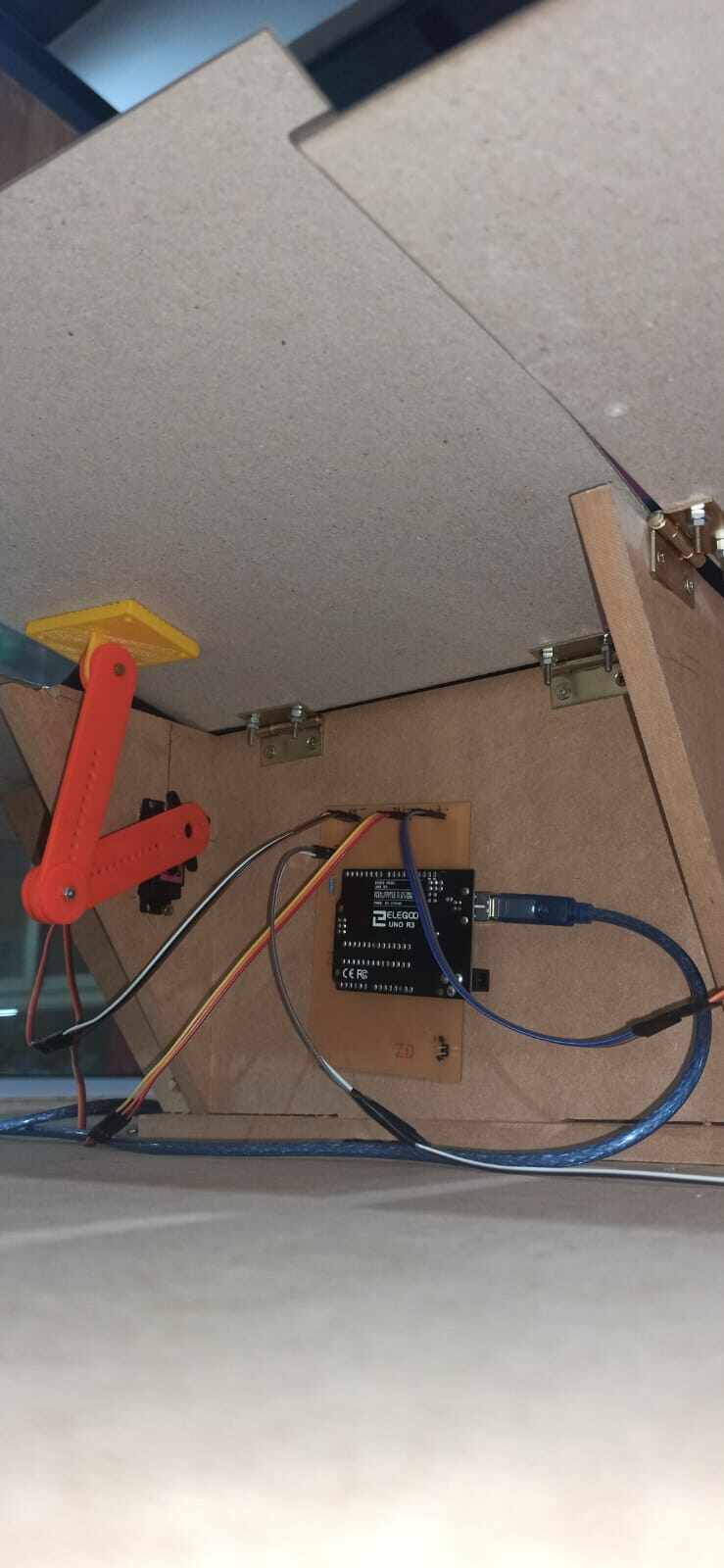
The information of the files is on the side with the fusion project and also the program that we made for esperancita to work.