17 Applications and Implications
This week's assignment is to propose a final project masterpiece that integrates the range of units covered.
Tot be? - a stacking lamp
This week was not only time to scope out the project but also to triage and decide which elements will be part of version 0 still covering: 2D and 3D design Additive and subtractive fabrication processes, Electronics design and production, Embedded microcontroller interfacing and programming, System integration and packaging.
What will it do?
Tot be? is a lamp that grows with a person's life adding shells that tell their personal story. Each shell represents another stage in the life of a person and explores another material and fabrication process. My idea is to create an individual shell that differs in shape and material, but follows the same measurements, but keep the structure, meaning the electronics, the fixture and power supply identical to make it a hidden tech part, easy to reproduce.
Who has done what beforehand?
Lamps are one of the most created projects in the designworld, stacking and with magnetic connections as well as Fabacademy Final Porjects. While I have included the design research in in my Project Development Page, I quickly want to elaborate about two final projects I took inspiration from:
- connection of different rings with magnets
- casted lampshade
- uses neopixel ring, light on top!
- ATmaga328p
- uses neopixel strip
- no extra case for light (3d printed part)
- ATTiny 84
What will you design?
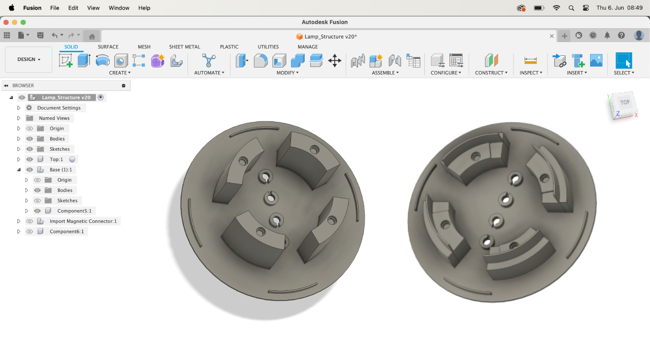
On the one hand there is the identical structure, that I will be designing with Fusion360:

- Top: contains 4 magnets and a magnet fixture to connect to the bottom
- Bottom: contatins 4 magnets, a socket for the neopixel, the pcb and a magnet fixture to connect to the top
On the other hand I am designing three different individual shells with Rhino and Grasshopper:

- clay piece: used Grasshopper to generate parametric curves and loft them to a final shape with Rhino.
- petg piece: used Rhino/Grasshopper to create a shape with isocurves.
- lasercut piece: used Rhino to draw the lines for valley and mountain cuts.
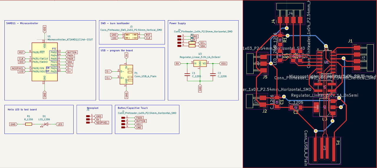
On top of that I am designing the PCB that controls the neopixel strip in each piece:

What materials and components will be used and how much will they cost?
- 3D-printed structural pieces: Polymaker PolyTerra PLA (a few cents)
- 3D-printed shell: Polymaker PolyLite PETG (a few cents)
- lasercut shell: Plakene Polypropylene (2-5 euros)
- lasercut base: Birch Plywood 4mm (2-7 euros)
- neopixel strip: Seeedstudio Grove 1-m (10 euros)
- 34 magnets: 6x2mm circular neodymium magnets (2-4 euros)
- pcb: double-sided copper clad board (1-5 euros)
- wire connection: WAGO inline connectors 221 (2-7 euros)
- AC/DC converter: AC/DC converter/USB (1 euro)
- USB cable: USB A cable (1 euro)
- 3x SAMD11 microcontrollers: ATSAMD11C14A-SSUT (3 euros)
- 3x voltage regulators 3.3V 1A: TC1262-3.3VDB (1,80 euros)
- 6 resistors 5k Ohm: RC0603FR-105K1L (a few cents)
- 6 capcitors 1 µF: Kemet C1210X105K5RAC3316 (a few cents)
- 3 LEDs: SM0805UGC (a few cents)
- pinnheaders: CONN HEADER SMD R/A 36POS 2.54MM (a few cents)
- smd pinnheaders: Males Header Dual Vertical (a few cents)
Where will they come from?
During the period of Fabacadmy the materials used will be provided by the Fablab Barcelona.
What parts and systems will be made?
- structure: combination of two 3D-printed PLA pieces that fix the magnets in the right place on top and bottom, hold the PCB and wire connections, connect to the capacitive touch button on the shell and fix the neopixel strip
- shell: 3D printed and lasercut shell pieces that follow the same dimensions: diameter 13 cm height 6.4 cm
- electronic system: one seperate pcb controlling each neopixel strip seperately with a capacitive touch button and one "parentboard" that controls the I2C network
What processes will be used?
- 3D printing: PETG, clay and PLA
- PCB milling
- lasercutting
- soldering
What questions need to be answered?
For now the concept is clear but still a few questions need to be answered or adjusted accordingly to the time available:
- Which on/off switch will be used? (button > capacitive touch button > sensor with capacitive wire)
- Which microcontroller will be used? (SAMD11 > SAMD21)
- How will I connect the structural top and bottom pieces? (magnet > simple locking machanism)
- How will I wire the magnets from top to bottom? (connectors > directly on the pcb)
- Which board will be the parentboard for the I2C network? (Barduino > self-designed board)
How will it be evaluated?
Mostly the success of the lamp strikes with the magnetic connection, whether they transfer the VDD, GND, SCL, SDA and each different piece will light up.