Final Project
Kunststof: final project development

How do you translate pulling, squeezing and stretching into something permanent?
A five bar linkage plotter on an easle that moves based on variable resistance input from knitted sensors on the other easle. The painting robot translates the manipulation of textiles directly into brush strokes. You have to figure out new ways to get the machine to do what you want in a human/machine collaborative effort.
The smaller easle has place for two interchangeable e-textiles sensors. You have to start with calibrating the sensors: press the CALIBRATE button and manipulate the sensors for five seconds. After that the painting robot gets to work, translating the touch of the textiles into an illustration. With the BRUSH button you can toggle the height of the brush, touching or hovering above the canvas.
Introduction
On this page I will talk about the entire process of making this installation. I documented this both as I went and after the fact. The document-as-you-go part consisted for a large part of me writing down what I was doing and what I encountered over a couple of weeks, so there was a lot of moving around and filtering to do after the fact since I changed back and forth with certain settings a couple of times and I worked on multiple parts of the project at the same time. I’ve divided the documentation into focus areas: the bill of materials, hardware, programming and installation development & design. Within those areas I’ve divided the parts by topic and within those topics I’ve tried to be as chronological as possible. Spiral development can turn documentation into a complex non-linear storyline, so I’ve tried my best to make it as readable as possible.
Research
I have changed my idea many, many times. To see all of the options I’ve considered and research I’ve done on those options, visit my project research page. Below the gif that decided the five bar linkage plotter direction for me.

BOM
PCBs
The following BOMs for the PCB exclude a 12V 5A power supply for the main board, a 4,5V battery pack and all of the (ribbon) wires and connectors.
Prices are unit prices from Digikey (where possible), excluding taxes. All components came from the lab so I didn’t pay for them myself. When bought in bulk, the unit prices are lower. I just used the unit price when buying one component. Actual cost of the PCBs is a little lower. Prices are apiece unless otherwise stated.
Main output board
The board controlling all of the motors on the installation.
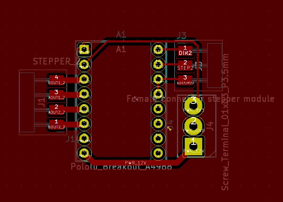
Stepper modules
Items per module; I’ve made 3 modules of which I only used 2.
Later I remade two boards with the DRV8825 instead of the A4988 and with a 17HS19 stepper motor; the driver modules have the same footprint so I didn’t change the design in KiCad.
| Component | Quantity | € | Datasheet | Notes |
| DRV8825 breakout | 1 | 2,22 | https://www.ti.com/product/DRV8825 | Price found here (11,09 / 5) |
| 17HS19-2004S1 Stepper Motor | 1 | 15,99 | https://pdf1.alldatasheet.com/datasheet-pdf/view/1141324/STEPPERONLINE/17HS19-2004S1.html | Price found here |
Input board
This is the board connected to the various e-textiles sensors and switches. It excludes regular yarn used for the sensors since I got the regular yarn mostly from my mom.
| Component | Quantity | € | Datasheet | Kicad Footprint | Notes |
|---|---|---|---|---|---|
| Schottky diode | 1 | 0,39 | https://www.digikey.nl/en/products/detail/stmicroelectronics/BAT46ZFILM/1207026 | fab:SOD-123 | |
| LED | 2 | 0,35 | https://www.digikey.nl/en/products/detail/lumex-opto-components-inc/SML-LX1206IC-TR/229140 | fab:LED 1206 | Red and orange |
| Vertical pin header 2x02 (2 to connect e-textiles, 1 for battery) | 3 | 0,80 | https://www.digikey.nl/en/products/detail/amphenol-icc-fci/20021121-00010T1LF/4243614 | fab:PinHeader 2x02 P2.54mm Vertical SMD | They’re too close to each other on the board so not optimal |
| Horizontal pin socket 1x06 | 1 | 0,84 | https://www.digikey.nl/en/products/detail/gct/BG300-06-A-L-A/9859597 | fab:PinHeader 1x06 P2.54mm Horizontal SMD | |
| XIAO-ESP32C3 | 1 | 4,53 | https://www.digikey.fi/en/products/detail/seeed-technology-co-ltd/113991054/16652880 | See socket | |
| XIAO-ESP32C3 Socket | 1 | Not applicable | fab:SeedStudio XIAO SocketSMD | Made with 2x vertical pin socket 1x03 and 2x vertical pin socket 1x04 | |
| 220 Ohm resistor | 2 | 0,09 | https://www.digikey.nl/en/products/detail/yageo/RC1206FR-07220RL/728693?s=N4IgTCBcDaIEoGECMYAMA2AYnAtKg7GGnADIgC6AvkA | fab:R 1206 | |
| 10k Ohm resistor | 2 | 0,09 | https://www.digikey.nl/en/products/detail/yageo/RC1206FR-0710KL/728483 | fab:R 1206 | |
| Tactile switch | 1 | 0,97 | https://www.digikey.nl/en/products/detail/omron-electronics-inc-emc-div/B3SN-3112P/27856 | fab:Button Omron B3SN 6.0x6.0mm | Pulled up internally |
| Conductive yarn | n.a. | 5 | I used various yarns from Bart & Francis, a little bit of each basically |
Installation
The materials that I used for my installation prototype were found in the attic of the Waag building or were from leftover stock that we bought a while back for the fablab, so I don’t know how much it originally cost. I looked for a similar alternatives online. For the actual installation (both easles) I used a piece of 9mm plywood of 900x2000mm.
| What? | Quantity | € | Notes |
|---|---|---|---|
| 3.6mm plywood | 1 | 22,10 | Based on the price here; for prototype easle, for the canvas of the actual easle and for the e-textiles frame (I used 5mm plywood for that though) |
| 5mm Plexiglas | 1 | 9,95 | Based on the price here; for prototype arms |
| 9mm plywood | 1 | 42,70 | Based on the price here; for the two easles |
| 3mm Plexiglas | 1 | 9,95 | Based on the price here; used transparent for the brush module guide and dark brown Plexiglas for the arms and big gears |
| 3D printing filament | 0,25kg (approx.) | 7,50 | I used this one |
| Wood glue | 1 | 2,79 | Based on the price here |
| 16x5x5.5mm bearings | 12 | 7,42 | Took them out of skateboard bearings; based on the price here |
| M3, M4, M5 bolts, nuts and washers | plenty | 3 | Estimation; if you get one of these boxes you’re golden |
| M5 bolt 45mm | 2 | 0,80 | Can be longer; based on price here; to connect arms to frame |
| M5 bolt 30mm | 2 | 0,25 | Based on price here; to connect the arms |
Hardware
This part is about all of the electronic hardware. The programming is discussed in the next part.
PCB development
Failed first attempt
I made this massive board to control three steppers and two servos. Long story short: it doesn’t work because I used the wrong stepper driver chips, so I redid the entire board and made it modular. See networking & communications for the documentation of my failed mother board.
Modular system
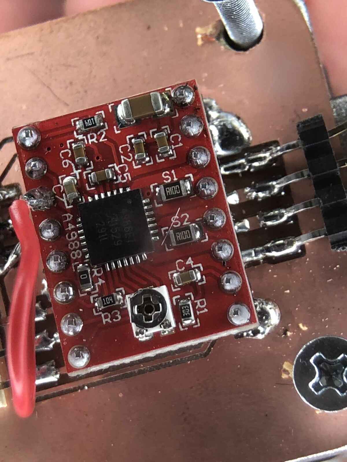
After the previous debacle I decided to be a little bit smarter and make my PCBs modular. The elements are still mostly the same except for the stepper motor driver elements that have been replaced by the A4988.
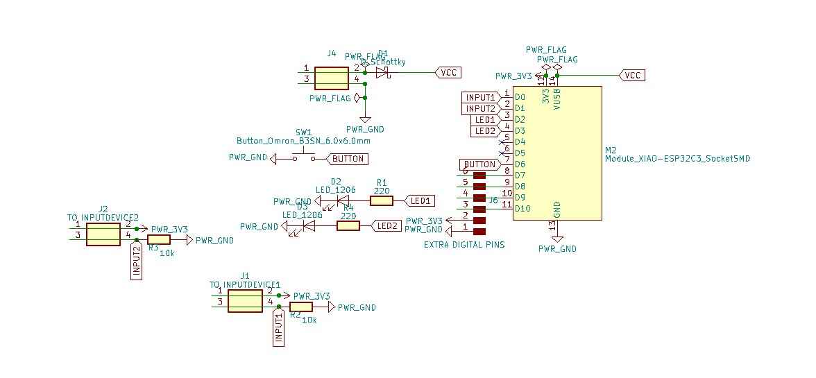
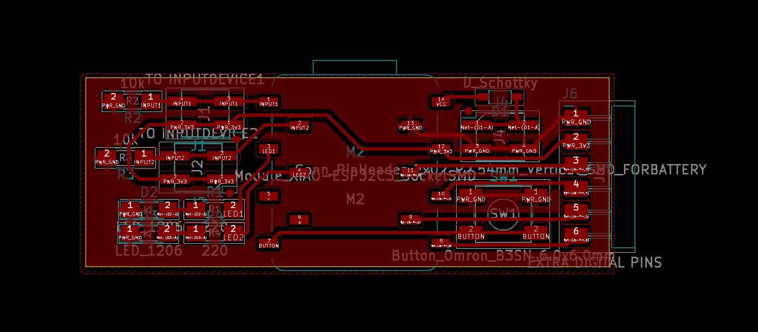
XIAO ESP32 input devices board PCB and schematic:
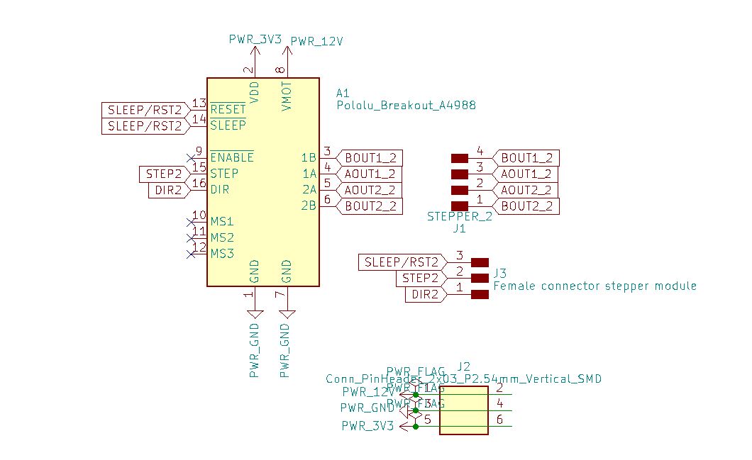
Stepper module schematic and PCB layout:
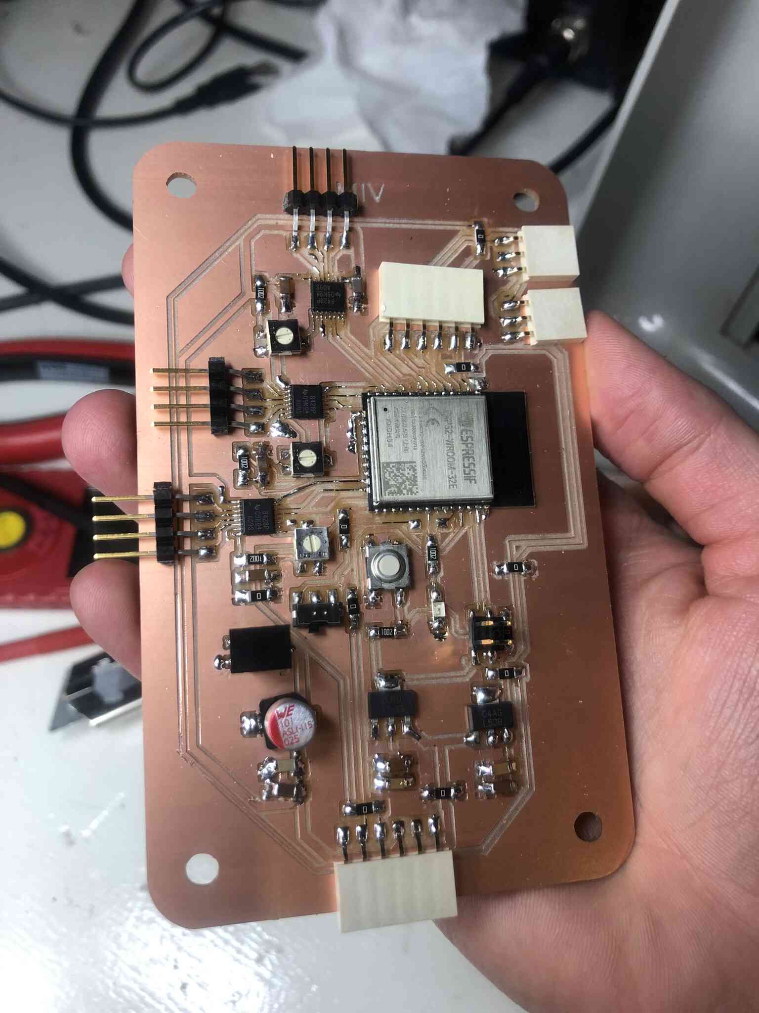
ESP32 WROOM main board schematic:
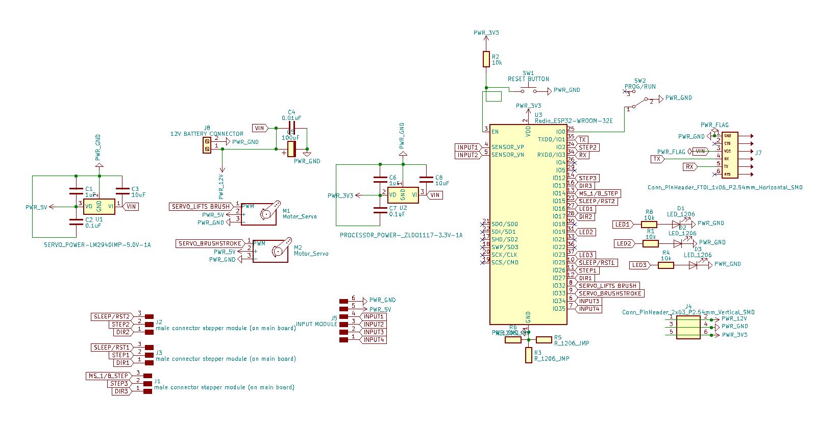
And the PCB layout:
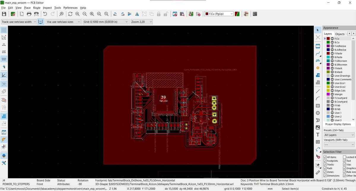
I did the edge cut in Illustrator because it was easier.
Some notes on the stepper motors:
- Since I want to be able to test the stepper motor while programming it, I’m adding the 5V power line to the 12V power line for VM (voltage for the motor). I just have to make sure that I’m not attaching 12V and 5V at the same time because that’s probably a bad idea (although the driver will probably just shut down because of its safety measures).
- Stepstick: I’m not connecting MS1, MS2 and MS3 because I don’t need microstepping for my purposes and because I don’t have enough pins; it can also done in hardware but I’m not doing that now (if I really need it I’ll make some bridges; this is what I did later).
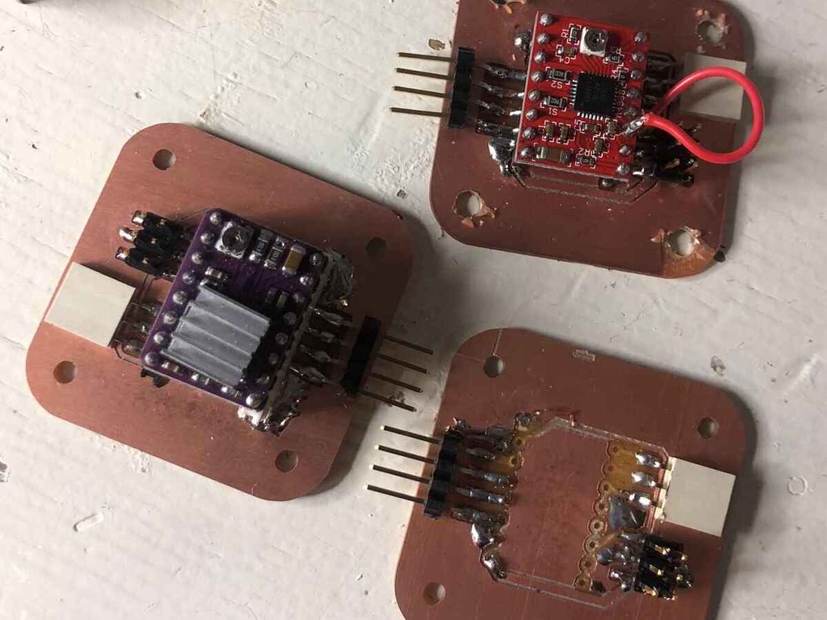
All the new boards milled and soldered:
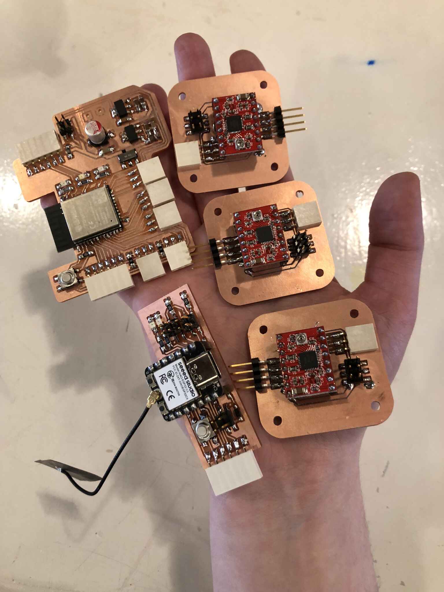
A couple of weeks later I made new stepper motor modules with the DRV8825, this time with female header pins so I could replace the chips easily. Since I didn’t want to change the KiCad design to save time I used PTH header pins that would fit in the holes in my previous design. In the end it took me a full day to make the new PCBs working because it was really hard to solder the header pins. I spent about 8 hours struggling with the new boards and setting the Vref. In the end, it was bad soldering and I’m embarrassed that it took me that long to figure out (or actually, Henk figured it out for me since I was too upset to notice apparently). The working result was messy and not my best solder work. They all didn’t work initially because I didn’t solder the boards well enough, and one of the boards started behaving erratically after a couple of hours because a solder connection failed. I had to make another one because I ripped off some traces after I soldered on a board that didn’t work and wanted to take it off. So my time-saving method actually cost me a lot of time and frustration.
Here you can see the new stepper motor driver, the old one at the top (with red wire microstepping bridge) and the broken one.
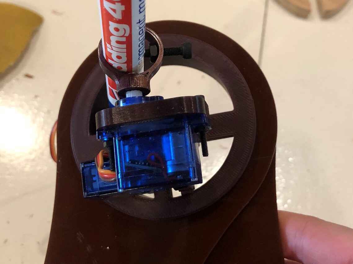
Stepper motors & drivers
I started out with a 17HS4401 motor controlled with a 4988 motor driver. I later upgraded to a 17HS19 motor that has a higher rated current and holding torque and to a DRV8825 motor driver that can provide more current. This part documents my battle against gravity, torque, speed and constantly bumping into new limitations.
Current limiting (4988)
The Nema17 motors I started with have a rated current of 1.7A per phase. I have to use the onboard potentiometer on the 4988 to limit the current (following this tutorial). I did this measurement while connected to 12V.
Vref = Current Limit / 2.5
In my case this is 1.7 / 2.5 = 0.68 Vref
I clipped the multimeter red pole to a small screwdriver and held the black pole to ground, then used the screwdriver to carefully turn the potentiometer on board until the multimeter displayed 0.68V.
One of the boards didn’t seem to work properly so I checked it but everything was connected how it should have been. Then I realized I set the Vref for that one at 0.068V instead of 0.68V (which is also why it was so hard to get the exact voltage on that board).
Correct Vref formula
Later when I was troubleshooting the torque (torque is the constant bane of my existence in my final project) I was thinking that the formula I used for calculating Vref wasn’t the right one, so I looked into it some more. Here the following formula is used:
VREF = Imax * 8 * Rs
Where Rsense is a value found on the stepstick. I checked mine and it had Rsense resistors with R100 written on them which means 0.1Ω.
1,7 * 8 * 0,1 = 1,36V
I currently have them set to 0,68V so that’s half of what I calculated above. The datasheet doesn’t tell me if the rated current of 1.7A is per phase (I later learned that it is indeed per phase) or in total so that left me a bit worried. I had another look at the steppermotorshop link where it explicitly says Each phase draws 1.5A,allowing for a holding torque of 42N.cm (60oz.in). That’s another rating than the datasheet says, but it is more clear. I also read that it’s always best to leave some margin and lower the current by around 10-20%; 10% as margin makes the current 1.5*0.9=1,35A. So to calculate Vref again:
1,35 * 8 * 0,1 = 1,08V
However I couldn’t set it to that voltage: for both stepsticks the voltage jumped from 0,82 to 1,82V with no possibility to set it accurately. According to posts on this forum the A4988 cannot deliver the current I want per coil. Checking back here they did mention that the A4988 has a current limitation of 1A per coil which means that I have to adjust my formula once more. This is written about the 4988:
These ones are the simplest and cheapest you can get and have a current limitation of about 1A per motor coil, which means 2A in total. However, this mostly depends on how cool you can keep the chip, either by using passive cooling (heatsink), active cooling (fan blowing air) or both (heatsink + fan).
I’m using only a heatsink, so pushing the driver to its absolute limit might not be the best.
1 * 8 * 0,1 = 0,8V
Which is also what I read in the forum. So I guess I’ll do that then.
At this point I also realized that I calculated my holding torque based on getting the full 1.5A per phase, so if I can only deliver 66% of that, my calculated holding torque will also be significantly lower. I don’t know if the holding torque and the rated current have a linear correlation, but I’m pretty sure less current means less torque any way you look at it.
Links:
- https://www.circuitist.com/how-to-set-driver-current-a4988-drv8825-tmc2208-tmc2209/ (Vref calculator)
- https://electronics.stackexchange.com/questions/436218/how-to-find-stepper-motors-rated-current-to-set-current-limit
Current limiting (DRV8825)
I upgraded from the 4988 to the DRV8825 after I tried to push the 4988 to its limit and I still had significant skipping of the motor, especially when moving the arm (with or without the outer arms attached). This is written about its features:
This breakout board for TI’s DRV8825 microstepping bipolar stepper motor driver features adjustable current limiting, over-current and over-temperature protection, and six microstep resolutions (down to 1/32-step). It operates from 8.2 V to 45 V and can deliver up to approximately 1.5 A per phase without a heat sink or forced air flow (rated for up to 2.2 A per coil with sufficient additional cooling). The driver has a pinout and interface that are nearly identical to those of our A4988 stepper motor driver carriers, so it can be used as a higher-performance drop-in replacement for those boards in many applications.
This one uses a different formula to calculate Vref:
Vref = Current Limit / 2
- 2 amps per coil for 17HS19-2004S1 which makes Vref 1
- 1,5 amps per coil for 1701HS which makes Vref 0,75 > starting with this since I also disabled microstepping for now
With this setting it’s not working for either drivers.
This is written in the datasheet of the DRV8825: Operational at VREF between 0 V and 1 V, but accuracy is degraded. I found that pretty strange because the maximum current it can handle is 2.2A which would mean that only between 2 and 2.2A the accuracy is good.
After replacing one of the A4988 drivers with the DRV8825 and disabling microstepping, I could see that the motor was skipping way less but still too much, so I decided to replace the weaker motors with the stronger 17HS19. I increased the Vref to 1V on the driver. This helped and was sufficient for my final project.
Nema 23 iteration
I ordered the 23HS8430 after my final project presentation which has a holding torque of 1,9Nm but it has a 3A rated current which my DRV8825 cannot provide. I looked into other options like the TB67S249FTG which has a peak current per phase of 4.5A, but it also costs around 15 euros which I don’t want to spend. I’m gonna see if I can manage with the DRV8825 max current of 2.2A (or 2.5A if I’m really going to push it); best case scenario is that the torque with 70% of the rated current is also about 70%, or at least more than the 0,59Nm of the Nema17 that I’m using now. I could calculate this but I’m just going to try it out.
The motors arrived and they’re significantly bigger and heavier than the Nema 17 motors I’ve been using so far. Moving the shaft by hand is way harder than moving the Nema17 shaft, which I hope indicates a way greater position holding power. To be continued!
https://opencircuit.nl/product/tb67s249ftg-stepper-motor-driver-compact-2
Links: https://www.pololu.com/product/2133 https://forum.arduino.cc/t/update-current-adjustment-for-motor-drivers-drv8825-a4988/400151/4
Servo motors
I started out with the high torque MG995 servo motor in mind to lift the entire brush mechanism. I changed this later to the SG90 Micro Servo since I decided to only lift the brush which required way less power. Unlike the stepper motors, servo motors work pretty much straight out of the box. The only frustration is figuring out the min and max PWM values for specific motors. Other than that they can be connected directly to a data pin (and power and ground).
Erratic behavior
One thing I noticed was that the servo was behaving irregularly when connected to the ESP WROOM when connected to my computer (powered via a SAMD11C serial bridge). I measured the voltage provided to the board and when it was a stable 4.8V it was running fine, but then it would randomly drop voltage both on the 5V power line (from 4.8 to 4.4 approximately) and on the data line to the servo. When running fine this fluctuates between about 200 and 310 mV, but it drops when the motor starts moving in random directions. When I connected the board to a 12V power supply, it was working fine and the 5V power line was outputting a stable 4.95V reading. So I think my issue was that the 5V provided by my computer was just too little to get a stable 5V via the 5V voltage regulator.
Power & wiring
I’m powering the main board from a 12V 5A (60 Watt) power supply. Some components need 3.3V, some 5V and some 12V. I am not sure yet how much current all of the motors will pull, but I want to make sure that I’m not frying that line. The rated current for the steppers I wanted to use at the point of this deep dive was 1.7A and I planned on using 3 of them. At this point I was still making a plotter on wheels so some of the information is no longer relevant.
Power in a circuit in series on the left and in parallel on the right (this is mostly a note to self):
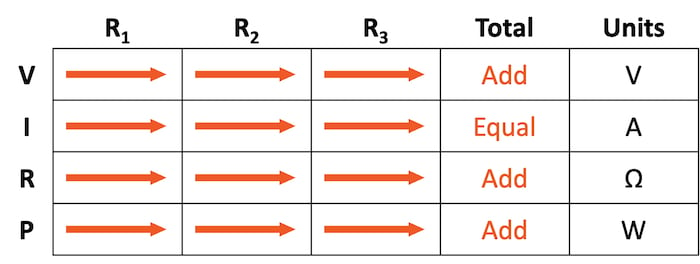
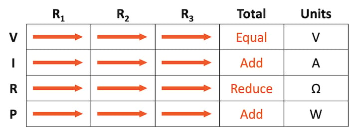
I need a bigger gauge wire for the 12V line, so I’m connecting it with a terminal instead. I’m wiring my power line in parallel, which means that the voltage is 12V everywhere, but the amperage has to be added. The rated current for the stepper motors I’m using is 1.7A, so for 3 motors running simultaneously they could pull 5.1A. You should always add a margin for spikes and for the length of the wire (more on that here).
AWG
The maximum length of the cable I’m going to use depends on whether I can use a battery instead of a power supply. In case of a battery I would need less than 50 centimeter while in case of a stationary power supply I would need a couple of meters depending on how big my final machine will be. I think 5 meters would be the absolute max.
Following this table then, I’m having a look at the 10 Amps row to be well within the limit (5 Amps would be just too little and then I don’t have a margin either). 10 feet equals about 3 meters, so I think 14 awg would be fine unless I’m going to use a really long wire (for reference: jumper wires range from AWG 20-26 generally; the higher the number the thinner the wire).
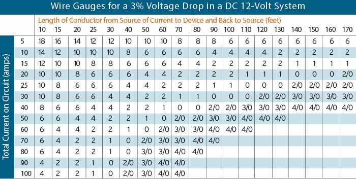
To make my life easier I’m using a terminal with 3 screws so I can connect the 3.3V line to the same terminal so all of the power is grouped together. The one we have in the lab are rated for 125V, 6A and AWG 28-16 so I guess I’m going to use an AWG 16 wire. I think that should be fine too; or I’ll try to squeeze the slightly thicker AWG 14 wire in.
Henk advised against using terminals though and we didn’t have the one I was looking for in the lab. Anyhow, for now I’m using 1x02 header pins and a ribbon wire with a couple of 2x02 connectors to power the 3 stepper modules. I didn’t really do anything with the AWG research: I figured I would just use the 28 AWG wires in the lab and see how it goes.
Programming
In this chapter of the documentation the focus is on the programming of the separate elements of this project. The subjects can roughly be divided into the servo motor, stepper motors, calibration and BLE. I programmed these elements (somewhat) isolated, then integrated them into the ‘master code’ for the input board and for the output board. Since I was working on elements of the code in spirals, sometimes you will find parts of code not discussed yet already in the ‘code so far’. Don’t worry, it will be discussed.
Servo toggling with button
I wanted to be able to lift the button from the canvas and to have a more interesting brush stroke by moving the brush back and forth. The latter I dropped during my weight reduction trials since it wasn’t very spectacular or necessary for my final project. I did make a prototype for it so can still do it in the future.
It made the most sense to me to be able to control the servo motor from the input device with a button of some sort, so I looked into examples of state switching with buttons. The positioning of the servo motors as well as the min and max values for the attach and write functions I found iteratively; I learned during output devices week already that datasheets for servo motors aren’t always accurate with the PWM information. Here you can see it in action:
This is the code I wrote to test out the push button in combination with a servo motor (the code on the board in the video above):
#include <ESP32Servo.h>

Servo myservo;  // create servo object to control a servo

int pos = 0;    // variable to store the servo position

int servoPin = 10;
const int buttonPin = 21;

int buttonState;            // the current reading from the input pin
int lastButtonState = LOW;  // the previous reading from the input pin

// the following variables are unsigned longs because the time, measured in
// milliseconds, will quickly become a bigger number than can be stored in an int.
unsigned long lastDebounceTime = 0;  // the last time the output pin was toggled
unsigned long debounceDelay = 50;    // the debounce time; increase if the output flickers


void setup() {
  Serial.begin(9600);
  while (!Serial) {
    ; // wait for serial port to connect. Needed for native USB port only
  }
  pinMode(buttonPin, INPUT_PULLUP);

  myservo.attach(servoPin, 400, 2500);
  myservo.write(140);
}

void loop() {
  int reading = digitalRead(buttonPin);

  // If the switch changed, due to noise or pressing:
  if (reading != lastButtonState) {
    // reset the debouncing timer
    lastDebounceTime = millis();
  }
  if ((millis() - lastDebounceTime) > debounceDelay) {

    // if the button state has changed:
    if (reading != buttonState) {
      buttonState = reading;

      if (buttonState == LOW) {
        Serial.println("buttonpressed");


        for (pos = 140; pos >= 0; pos -= 1) { // goes from 180 degrees to 0 degrees
          myservo.write(pos);    // tell servo to go to position in variable 'pos'
          delay(15);             // waits 15ms for the servo to reach the position
        }

        for (pos = 0; pos <= 140; pos += 1) { // goes from 0 degrees to 180 degrees
          // in steps of 1 degree
          myservo.write(pos);    // tell servo to go to position in variable 'pos'
          delay(3);             // waits 15ms for the servo to reach the position
        }
      }

    }
  }
  lastButtonState = reading;

}
Stepper motors & drivers
AccelStepper library
Since I’m controlling multiple steppers I’m going to use a library called AccelStepper. I used the example code MultiStepper from the library to test the motors. I had to change the pins to the ones I’m using and I added some lines to set the pinMode for the sleep and enable pins on high to enable the motors.
Here you can see the motors working (I’m using a 12V power supply); powering two wheels and the beehive axis on the first iteration of my final project, when I was still making a robot on wheels. The steppers for the wheels are moving in the same direction but since they’re on opposite sides, they’re working against each other. But at least they all work!
Code used in the example above:
// Include the AccelStepper Library
#include <AccelStepper.h>

// Define pin connections
const int dirPin1 = 27;
const int stepPin1 = 26;
const int sleepResetPin1 = 25;

const int dirPin2 = 17;
const int stepPin2 = 2;
const int sleepResetPin2 = 15;


const int dirPin3 = 13;
const int stepPin3 = 12;
const int sleepResetPin3 = 14;

// Define motor interface type
#define motorInterfaceType 1

// Creates an instance
AccelStepper myStepper1(motorInterfaceType, stepPin1, dirPin1);
AccelStepper myStepper2(motorInterfaceType, stepPin2, dirPin2);
AccelStepper myStepper3(motorInterfaceType, stepPin3, dirPin3);


void setup() {
  // set the maximum speed, acceleration factor,
  // initial speed and the target position
  myStepper1.setMaxSpeed(1000);
  myStepper1.setAcceleration(50);
  myStepper1.setSpeed(200);
  myStepper1.moveTo(200);

  myStepper2.setMaxSpeed(1000);
  myStepper2.setAcceleration(50);
  myStepper2.setSpeed(200);
  myStepper2.moveTo(200);

  myStepper3.setMaxSpeed(1000);
  myStepper3.setAcceleration(50);
  myStepper3.setSpeed(200);
  myStepper3.moveTo(200);


  pinMode(sleepResetPin1, HIGH);
  pinMode(sleepResetPin2, HIGH);
  pinMode(sleepResetPin2, HIGH);

  delay(1);
}

void loop() {
  // Change direction once the motor reaches target position
  if (myStepper1.distanceToGo() == 0)
    myStepper1.moveTo(-myStepper1.currentPosition());

  // Move the motor one step
  myStepper1.run();

  if (myStepper2.distanceToGo() == 0)
    myStepper2.moveTo(-myStepper2.currentPosition());

  // Move the motor one step
  myStepper2.run();

    if (myStepper3.distanceToGo() == 0)
    myStepper3.moveTo(-myStepper3.currentPosition());

  // Move the motor one step
  myStepper3.run();
}
Absolute positioning
From the accelstepper missing manual:
moveTo((long) absolute_position)
  Argument: absolute_position in steps. The desired absolute position of type long. May be positive or negative.
Set the target position. The run() function will try to move the motor (at most one step per call) from the current position to the target position set by the most recent call to this function. Caution: moveTo() also recalculates the speed for the next step.  If you are trying to use constant speed movements, you should call setSpeed() after calling moveTo(). If moveTo() is called while the motor is moving,the target position is changed immediately and the acceleration algorithm is used to calculate the new speed. If the motor is running at a high speed in a particular direction and the new target position is in the opposite direction, the motor will continue to run in the same direction, decelerate to stop, then accelerate in the new direction until it approaches the new target and slows to a stop.
Speed and torque
Since I need 3 full revolutions to move the bigger arm gear one revolution, I tried mapping the values from 0-600 instead of 0-200 but that didn’t work as I expected initially. I tried without the upper arms and then I could get a full revolution but I think I’m overloading the board with position data for the steppers or the steppers want to finish their motion before they accept a next position so you don’t see a clear relationship between changing values with the potentiometer. If I’m sliding the potentiometer more often than the arms can move within the same timespan it’s becoming messy. You can also see that the arms are struggling to keep their position.
I first tried to fix this in the code. On the Accelstepper reference I read this:
The fastest motor speed that can be reliably supported is about 4000 steps per second at a clock frequency of 16 MHz on Arduino such as Uno etc. Faster processors can support faster stepping speeds. However, any speed less than that down to very slow speeds (much less than one per second) are also supported, provided the run() function is called frequently enough to step the motor whenever required for the speed set. Calling setAcceleration() is expensive, since it requires a square root to be calculated.
I tried the following (top two paragraphs are in the setup, bottom two in the loop) instead of using moveTo and run. That didn’t work how I expected however, moving very jittery and slowly.
  myStepper1.setMaxSpeed(1000);
  //  myStepper1.setAcceleration(50);
  myStepper1.setSpeed(1000);
  myStepper1.moveTo(0);

  myStepper2.setMaxSpeed(1000);
  //  myStepper2.setAcceleration(50);
  myStepper2.setSpeed(1000);
  myStepper2.moveTo(0);


      myStepper1.setSpeed(1000);
      myStepper1.moveTo(sensorValue1);
      myStepper1.runSpeedToPosition();

      myStepper2.setSpeed(1000);
      myStepper2.moveTo(sensorValue2);
      myStepper2.runSpeedToPosition();
When setting it back to a moveTo and run in combination with setAcceleration it’s running faster and smoother. I did a lot of trial and error and finally I got it to work. Here you can see smooth motion and an obvious correlation between sliding the potentiometer and the movement of the arm.
However, once the other two arms and the brush module are attached, it’s not so smooth. The weight seems to be too much for the small motors. Only when moving very slowly with the potentiometers it works somewhat, although you can see that the motors are struggling to keep the arms in place. As soon as the motor can’t hold it anymore, the arms fall down a bit, after which the motor thinks it’s somewhere else than where it is. Since I’m using a physical end stop to stop the arms from falling the other way, that is an issue: the motor tries to continue in a direction it can’t go in, and get’s even more lost in its position which you can also see in the video. Now that I have the code somewhat set, it’s time to fix these regular crashes.
Microstepping
I wasn’t using microstepping before because I read that you can have higher torque when in full step mode, and I don’t need a very high precision of steps.
This is what I read online about it (via www.brainy-bits.com):
For example using Full steps you might be able to reach close to 4 rotation a second at max speed, well if using 1/4 steps that maximum speed might be reduced to only 1 rotation a second.
This has nothing to do with the Stepper Motor itself, it’s a combination of the stepper driver and the micro controller maximum speed at which it can turn on and off the motor coils.
One other compromise might be about the maximum torque that can be achieve.
Although this is debatable, using Full steps normally will result in higher torque compared to micro stepping.
So in conclusion, if you’re project requires maximum speed, maybe using Full steps is the way to go.
On the other hand if you need more precision, then using micro stepping is a better choice.
Keep in mind that using a faster micro controller and better stepper driver will affect these choices.
However while testing out accelerations and speeds I noticed the stepper was stalling and skipping steps quite a bit and I read that it could be because of misalignment between the windings and rotor:
The skipping steps is when the synchronization between the electrical windings and the mechanical rotor go out of alignment. The electrical part of it can move faster than the mechanical part of it can respond, so that can make it lose synchronization. Skipping steps is simply a little bit of a misalignment, whereas a full-blown stalling is when the rotor stops, and the current continues on around the windings trying to command it to move with the rotor actually stopped. This could be because the electrical windings are trying to move faster than the rotor. It could also be because the amount of magnetic force that keeps them synchronized has been exceeded so that the mechanics are no longer attracted to the magnetism of the windings.
Here you can see the skipping of steps pretty well:
One solution for this can be microstepping. After trying out various combinations of setMaxSpeed, setAcceleration and setSpeed in full step mode I tried to set microstepping to 1/4 which did seem to help (for this you do need to set the speeds and acceleration higher, times 4 basically) because of the answer given here. The moveTo also has to be multiplied by 4. It was 600 because I have two gears with a ratio of 1:3 so one revolution of the arm on my installation means 3 revolutions of the stepper motor. One revolution in full step mode is 200 steps (1.8 degrees). Times 4 is 2400.
With these settings and microstepping set to 1/4 the stepper moved pretty smoothly:
  myStepper1.setMaxSpeed(4000);
  myStepper1.setAcceleration(4000);
  myStepper1.setSpeed(4000);
  myStepper1.moveTo(2400);
I used a bridge from the MS2 pin to the 3.3V line to enable 1/4 step.
Half step
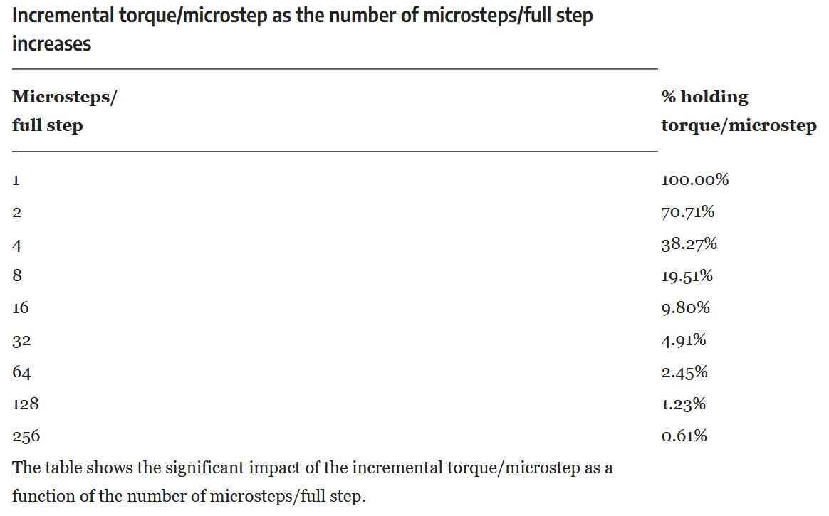
While quarter stepping worked well when the motor wasn’t attached to the installation, I ran into a lot of torque issues in the actual setting. I had another look at the relation between microstepping and torque. I found this table and the loss of torque is already at over 60% when doing 4 microsteps. As a compromise, I switched to 2 microsteps. In that case I only lose about 30% of torque which I hoped would leave me with enough torque.
At this point I changed the microstepping resolution to 1/2 while keeping the code on the client side the same. I changed the mapped stepper motor position values on the server side from 0-1200 to 0-600 so the range of the movement (0-180 degrees, 1200 would be a full rotation) would be the same and I halved the speeds and acceleration.
sensorValue1 = map(sensorValue1, sensorMin1, sensorMax1, 0, 600);
Sadly this didn’t help at all. Then I decreased the speeds even further in the client code (600 speed and 300 acceleration). I also added a line to set the new 0 position to be within the canvas. It was still skipping a lot of steps and it was just too slow now.
Another thing I read that I could do is increase the voltage input (to 18 or 24), but that doesn’t work for my voltage regulators which work up until 12V input voltage. A workaround would be to power the stepper modules separately from the board but it would be an unelegant wire mess and I don’t have time to make another board. I could also replace the A4988 with the DRV8825 since it can handle more than double the current (2.2A per coil) and it can be used as a drop-in replacement since they have the same pin-out. This last option is what I did in the end, as well as going back to full step mode to regain some more torque since the lack of enough torque was the biggest cause of skipping steps. Full step ended up working smooth and fast enough.
Links:
UniversalTimer
At first the motor was only working smoothly in an isolated setting when only testing the motor and nothing else. In my actual code, it was even slower than before, so I had a look at my loop and the Accelstepper reference. I set the delay for sending values from my input board to 50ms and in the loop on my output board I have if (pRemoteCharacteristic->canRead()) { > run stepper motor. I read in the documentation that every time run is called, it does one step. This means that it’s only doing one step every 50ms (probably even a bit more ms). So, running the motor should happen as often as possible, which means that I have to move some things around in my main loop. I fixed this by adding a timer (using the UniversalTimer library). Current output board code below:
/**
   A BLE client example that is rich in capabilities.
   There is a lot new capabilities implemented.
   author unknown
   updated by chegewara
   Modified by Michelle Vossen
*/

#include "BLEDevice.h"
//#include "BLEScan.h"
#include <AccelStepper.h>
#include <UniversalTimer.h>

UniversalTimer timer(500, true);

// Define pin connections for steppers

const int dirPin1 = 27;
const int stepPin1 = 26;
const int sleepResetPin1 = 25;

const int dirPin2 = 17;
const int stepPin2 = 2;
const int sleepResetPin2 = 15;

//const int dirPin3 = 13;
//const int stepPin3 = 12;
//const int sleepResetPin3 = 14;

// Define motor interface type
#define motorInterfaceType 1

// Creates an instance
AccelStepper myStepper1(motorInterfaceType, stepPin1, dirPin1);
AccelStepper myStepper2(motorInterfaceType, stepPin2, dirPin2);
//AccelStepper myStepper3(motorInterfaceType, stepPin3, dirPin3);

// To convert the incoming string into ints
int i;
char delimiter[] = ",";
char *p;
char string[128];
String sensorValuesString[2];
int sensorValue1;
int sensorValue2;
String valueString;

BLERemoteService* pRemoteService;
BLEClient*  pClient;

// The remote service we wish to connect to.
static BLEUUID serviceUUID("4fafc201-1fb5-459e-8fcc-c5c9c331914b");
// The characteristic of the remote service we are interested in.
static BLEUUID    charUUID("beb5483e-36e1-4688-b7f5-ea07361b26a8");

static boolean doConnect = false;
static boolean connected = false;
static boolean doScan = false;
static BLERemoteCharacteristic* pRemoteCharacteristic;
static BLEAdvertisedDevice* myDevice;

static void notifyCallback(
  BLERemoteCharacteristic* pBLERemoteCharacteristic,
  uint8_t* pData,
  size_t length,
  bool isNotify) {
  Serial.print("Notify callback for characteristic ");
  Serial.print(pBLERemoteCharacteristic->getUUID().toString().c_str());
  Serial.print(" of data length ");
  Serial.println(length);
  Serial.print("data: ");
  Serial.write(pData, length);
  Serial.println();
}

class MyClientCallback : public BLEClientCallbacks {
    void onConnect(BLEClient* pclient) {
    }

    void onDisconnect(BLEClient* pclient) {
      connected = false;
      Serial.println("onDisconnect");
    }
};

bool connectToServer() {
  Serial.print("Forming a connection to ");
  Serial.println(myDevice->getAddress().toString().c_str());

  pClient  = BLEDevice::createClient();
  Serial.println(" - Created client");

  pClient->setClientCallbacks(new MyClientCallback());

  // Connect to the remote BLE Server.
  pClient->connect(myDevice);  // if you pass BLEAdvertisedDevice instead of address, it will be recognized type of peer device address (public or private)
  Serial.println(" - Connected to server");
  pClient->setMTU(517); //set client to request maximum MTU from server (default is 23 otherwise)

  // Obtain a reference to the service we are after in the remote BLE server.
  pRemoteService = pClient->getService(serviceUUID);
  if (pRemoteService == nullptr) {
    Serial.print("Failed to find our service UUID: ");
    Serial.println(serviceUUID.toString().c_str());
    pClient->disconnect();
    return false;
  }
  Serial.println(" - Found our service");


  // Obtain a reference to the characteristic in the service of the remote BLE server.
  pRemoteCharacteristic = pRemoteService->getCharacteristic(charUUID);
  if (pRemoteCharacteristic == nullptr) {
    Serial.print("Failed to find our characteristic UUID: ");
    Serial.println(charUUID.toString().c_str());
    pClient->disconnect();
    return false;
  }
  Serial.println(" - Found our characteristic");

  // Read the value of the characteristic.
  if (pRemoteCharacteristic->canRead()) {
    std::string value = pRemoteCharacteristic->readValue();
    Serial.print("The characteristic value was: ");
    Serial.println(value.c_str());
  }

  if (pRemoteCharacteristic->canNotify())
    pRemoteCharacteristic->registerForNotify(notifyCallback);

  connected = true;
  return true;
}
/**
   Scan for BLE servers and find the first one that advertises the service we are looking for.
*/
class MyAdvertisedDeviceCallbacks: public BLEAdvertisedDeviceCallbacks {
    /**
        Called for each advertising BLE server.
    */
    void onResult(BLEAdvertisedDevice advertisedDevice) {
      Serial.print("BLE Advertised Device found: ");
      Serial.println(advertisedDevice.toString().c_str());

      // We have found a device, let us now see if it contains the service we are looking for.
      if (advertisedDevice.haveServiceUUID() && advertisedDevice.isAdvertisingService(serviceUUID)) {

        BLEDevice::getScan()->stop();
        myDevice = new BLEAdvertisedDevice(advertisedDevice);
        doConnect = true;
        doScan = true;

      } // Found our server
    } // onResult
}; // MyAdvertisedDeviceCallbacks


void setup() {
  Serial.begin(115200);
  while (!Serial) {
    ; // wait for serial port to connect. Needed for native USB port only
  }
  Serial.println("Starting Arduino BLE Client application...");
  BLEDevice::init("");

  // Retrieve a Scanner and set the callback we want to use to be informed when we
  // have detected a new device.  Specify that we want active scanning and start the
  // scan to run for 5 seconds.
  BLEScan* pBLEScan = BLEDevice::getScan();
  pBLEScan->setAdvertisedDeviceCallbacks(new MyAdvertisedDeviceCallbacks());
  pBLEScan->setInterval(1349);
  pBLEScan->setWindow(449);
  pBLEScan->setActiveScan(true);
  pBLEScan->start(5, false);

  myStepper1.setMaxSpeed(4000);
  myStepper1.setAcceleration(4000);
  myStepper1.setSpeed(4000);
  myStepper1.moveTo(0);

  myStepper2.setMaxSpeed(4000);
  myStepper2.setAcceleration(4000);
  myStepper2.setSpeed(4000);
  myStepper2.moveTo(0);

  timer.start();
} // End of setup.


// This is the Arduino main loop function.
void loop() {
  //      Serial.println(sensorValue1);
  //      Serial.println(sensorValue2);

  if (myStepper1.distanceToGo() == 0)
    myStepper1.moveTo(sensorValue1);

  // Move the motor one step
  myStepper1.run();

  if (myStepper2.distanceToGo() == 0)
    myStepper2.moveTo(-sensorValue2);

  // Move the motor one step
  myStepper2.run();

  if (timer.check()) {

    // If the flag "doConnect" is true then we have scanned for and found the desired
    //z BLE Server with which we wish to connect.  Now we connect to it.  Once we are
    // connected we set the connected flag to be true.
    if (doConnect == true) {
      if (connectToServer()) {
        Serial.println("We are now connected to the XIAO ESP BLE Server.");
      } else {
        Serial.println("We have failed to connect to the server; there is nothing more we will do.");
      }
      doConnect = false;
    }

    if (connected) {
      // Read the value of the characteristic.
      if (pRemoteCharacteristic->canRead()) {
        std::string value = pRemoteCharacteristic->readValue();
        //      Serial.print("The characteristic value was: ");
        //      Serial.println(value.c_str());

        // Convert received data to two separate integers
        char *cstr = &value[0];
        i = 0;
        p = strtok(cstr, delimiter);

        while (p && i < 2)
        {
          sensorValuesString[i] = p;
          p = strtok(NULL, delimiter);
          ++i;
        }

        sensorValue1 = sensorValuesString[0].toInt();
        sensorValue2 = sensorValuesString[1].toInt();
        return;
      }
    } else if (doScan) {
      BLEDevice::getScan()->start(0);
      return;
    }
  }
}
BLE
During networking and communications I figured out how BLE works and how to communicate wirelessly between boards. For the programming of both ESPs for my final project I continued building on that code. In that code I also had the calibration code I used for my embroidered board; you can see that code in action here. This time I had a button to recalibrate integrated in the PCB so I changed the code accordingly.
I started out with sending the data of one sensor, but I actually need the values from two sensors. I first tried to add another characteristic but it was making my code unnecessarily messy. I then figured that since I was sending the sensor data as a cstring, I might as well send two values in one line, and then unpack the values like I did during interface and application programming.
On the left you can see the server board with the sensors, on the right the client board with the motors.
BLE Client code so far:
/**
   A BLE client example that is rich in capabilities.
   There is a lot new capabilities implemented.
   author unknown
   updated by chegewara
   Modified by Michelle Vossen
*/

#include "BLEDevice.h"
//#include "BLEScan.h"


BLERemoteService* pRemoteService;
BLEClient*  pClient;

// The remote service we wish to connect to.
static BLEUUID serviceUUID("4fafc201-1fb5-459e-8fcc-c5c9c331914b");
// The characteristic of the remote service we are interested in.
static BLEUUID    charUUID("beb5483e-36e1-4688-b7f5-ea07361b26a8");

static boolean doConnect = false;
static boolean connected = false;
static boolean doScan = false;
static BLERemoteCharacteristic* pRemoteCharacteristic;
static BLEAdvertisedDevice* myDevice;

static void notifyCallback(
  BLERemoteCharacteristic* pBLERemoteCharacteristic,
  uint8_t* pData,
  size_t length,
  bool isNotify) {
  Serial.print("Notify callback for characteristic ");
  Serial.print(pBLERemoteCharacteristic->getUUID().toString().c_str());
  Serial.print(" of data length ");
  Serial.println(length);
  Serial.print("data: ");
  Serial.write(pData, length);
  Serial.println();
}

class MyClientCallback : public BLEClientCallbacks {
    void onConnect(BLEClient* pclient) {
    }

    void onDisconnect(BLEClient* pclient) {
      connected = false;
      Serial.println("onDisconnect");
    }
};

bool connectToServer() {
  Serial.print("Forming a connection to ");
  Serial.println(myDevice->getAddress().toString().c_str());

  pClient  = BLEDevice::createClient();
  Serial.println(" - Created client");

  pClient->setClientCallbacks(new MyClientCallback());

  // Connect to the remove BLE Server.
  pClient->connect(myDevice);  // if you pass BLEAdvertisedDevice instead of address, it will be recognized type of peer device address (public or private)
  Serial.println(" - Connected to server");
  pClient->setMTU(517); //set client to request maximum MTU from server (default is 23 otherwise)

  // Obtain a reference to the service we are after in the remote BLE server.
  pRemoteService = pClient->getService(serviceUUID);
  if (pRemoteService == nullptr) {
    Serial.print("Failed to find our service UUID: ");
    Serial.println(serviceUUID.toString().c_str());
    pClient->disconnect();
    return false;
  }
  Serial.println(" - Found our service");


  // Obtain a reference to the characteristic in the service of the remote BLE server.
  pRemoteCharacteristic = pRemoteService->getCharacteristic(charUUID);
  if (pRemoteCharacteristic == nullptr) {
    Serial.print("Failed to find our characteristic UUID: ");
    Serial.println(charUUID.toString().c_str());
    pClient->disconnect();
    return false;
  }
  Serial.println(" - Found our characteristic");

  // Read the value of the characteristic.
  if (pRemoteCharacteristic->canRead()) {
    std::string value = pRemoteCharacteristic->readValue();
    Serial.print("The characteristic value was: ");
    Serial.println(value.c_str());
  }

  if (pRemoteCharacteristic->canNotify())
    pRemoteCharacteristic->registerForNotify(notifyCallback);

  connected = true;
  return true;
}
/**
   Scan for BLE servers and find the first one that advertises the service we are looking for.
*/
class MyAdvertisedDeviceCallbacks: public BLEAdvertisedDeviceCallbacks {
    /**
        Called for each advertising BLE server.
    */
    void onResult(BLEAdvertisedDevice advertisedDevice) {
      Serial.print("BLE Advertised Device found: ");
      Serial.println(advertisedDevice.toString().c_str());

      // We have found a device, let us now see if it contains the service we are looking for.
      if (advertisedDevice.haveServiceUUID() && advertisedDevice.isAdvertisingService(serviceUUID)) {

        BLEDevice::getScan()->stop();
        myDevice = new BLEAdvertisedDevice(advertisedDevice);
        doConnect = true;
        doScan = true;

      } // Found our server
    } // onResult
}; // MyAdvertisedDeviceCallbacks


void setup() {
  Serial.begin(115200);
  while (!Serial) {
    ; // wait for serial port to connect. Needed for native USB port only
  }

  Serial.println("Starting Arduino BLE Client application...");
  BLEDevice::init("");

  // Retrieve a Scanner and set the callback we want to use to be informed when we
  // have detected a new device.  Specify that we want active scanning and start the
  // scan to run for 5 seconds.
  BLEScan* pBLEScan = BLEDevice::getScan();
  pBLEScan->setAdvertisedDeviceCallbacks(new MyAdvertisedDeviceCallbacks());
  pBLEScan->setInterval(1349);
  pBLEScan->setWindow(449);
  pBLEScan->setActiveScan(true);
  pBLEScan->start(5, false);
} // End of setup.


// This is the Arduino main loop function.
void loop() {

  // If the flag "doConnect" is true then we have scanned for and found the desired
  // BLE Server with which we wish to connect.  Now we connect to it.  Once we are
  // connected we set the connected flag to be true.
  if (doConnect == true) {
    if (connectToServer()) {
      Serial.println("We are now connected to the XIAO ESP BLE Server.");
    } else {
      Serial.println("We have failed to connect to the server; there is nothing more we will do.");
    }
    doConnect = false;
  }

  // If we are connected to a peer BLE Server, update the characteristic each time we are reached
  // with the current time since boot.
  if (connected) {
    // Read the value of the characteristic.
    if (pRemoteCharacteristic->canRead()) {
      std::string value = pRemoteCharacteristic->readValue();
      Serial.print("The characteristic value was: ");
      Serial.println(value.c_str());
    }
//    pRemoteCharacteristic->writeValue("Hello");
  } else if (doScan) {
    BLEDevice::getScan()->start(0);
  }

  delay(10); // Delay a second between loops.
} // End of loop
BLE Server code so far:
#include <BLEDevice.h>
#include <BLEUtils.h>
#include <BLEServer.h>

BLEServer *pServer;
BLEService *pService;
BLECharacteristic *pCharacteristic;

#define SERVICE_UUID        "4fafc201-1fb5-459e-8fcc-c5c9c331914b"
#define CHARACTERISTIC_UUID "beb5483e-36e1-4688-b7f5-ea07361b26a8"


const int sensorPin1 = 2;
const int sensorPin2 = 3;

const int ledPin1 = 4;
const int ledPin2 = 5;

const int buttonPin = 21;

int sensorValue1 = 0;   // the sensor value
int sensorMin1 = 4095;  // minimum sensor value
int sensorMax1 = 0;     // maximum sensor value

int sensorValue2 = 0;   // the sensor value
int sensorMin2 = 4095;  // minimum sensor value
int sensorMax2 = 0;     // maximum sensor value

int ledState1 = LOW;        // the current state of the output pin
int ledState2 = LOW;        // the current state of the output pin
int buttonState;            // the current reading from the input pin
int lastButtonState = LOW;  // the previous reading from the input pin

// the following variables are unsigned longs because the time, measured in
// milliseconds, will quickly become a bigger number than can be stored in an int.
unsigned long lastDebounceTime = 0;  // the last time the output pin was toggled
unsigned long debounceDelay = 50;    // the debounce time; increase if the output flickers


void setup() {
  // turn on LED to signal the start of the calibration period:
  Serial.begin(115200);
  while (!Serial) {
    ; // wait for serial port to connect. Needed for native USB port only
  }
  pinMode(ledPin1, OUTPUT);
  pinMode(ledPin2, OUTPUT);
  pinMode(sensorPin1, INPUT);
  pinMode(sensorPin2, INPUT);
  pinMode(buttonPin, INPUT_PULLUP);

  digitalWrite(ledPin1, ledState1);
  digitalWrite(ledPin2, ledState2);

  Serial.println("Starting BLE work!");

  BLEDevice::init("XIAO input device board");

  // C++ code: in class BLEDevice we call createServer(); this method returns a pointer (=address)
  // of type BLEServer and we store that in a variable named pServer of type pointer to BLEServer
  // (BLEServer *).
  pServer = BLEDevice::createServer();

  pService = pServer->createService(SERVICE_UUID);
  pCharacteristic = pService->createCharacteristic(
                       CHARACTERISTIC_UUID,
                       BLECharacteristic::PROPERTY_READ |
                       BLECharacteristic::PROPERTY_WRITE
                     );

  pService->start();
  // BLEAdvertising *pAdvertising = pServer->getAdvertising();  // this still is working for backward compatibility
  BLEAdvertising *pAdvertising = BLEDevice::getAdvertising();
  pAdvertising->addServiceUUID(SERVICE_UUID);
  pAdvertising->setScanResponse(true);
  pAdvertising->setMinPreferred(0x06);  // functions that help with iPhone connections issue
  pAdvertising->setMinPreferred(0x12);
  BLEDevice::startAdvertising();
  Serial.println("Characteristic defined");
}

void loop() {
  int reading = digitalRead(buttonPin);

  // If the switch changed, due to noise or pressing:
  if (reading != lastButtonState) {
    // reset the debouncing timer
    lastDebounceTime = millis();
  }

  if ((millis() - lastDebounceTime) > debounceDelay) {

    // if the button state has changed:
    if (reading != buttonState) {
      buttonState = reading;

      // only toggle the LED if the new button state is HIGH
      if (buttonState == LOW) {
        Serial.println("start");
        digitalWrite(ledPin1, HIGH);
        digitalWrite(ledPin2, HIGH);

        // determine min and max values of both sensors for 5 seconds
        for (int timems = 0; timems < 5000; timems++) {
          sensorValue1 = analogRead(sensorPin1);
          sensorValue2 = analogRead(sensorPin2);

          // record the maximum sensor value
          if (sensorValue1 > sensorMax1) {
            sensorMax1 = sensorValue1;
          }
          // record the maximum sensor value
          if (sensorValue2 > sensorMax2) {
            sensorMax2 = sensorValue2;
          }

          // record the minimum sensor value
          if (sensorValue1 < sensorMin1) {
            sensorMin1 = sensorValue1;
          }
          // record the minimum sensor value
          if (sensorValue2 < sensorMin2) {
            sensorMin2 = sensorValue2;
          }
          delay(1);
        }
        // signal the end of the calibration period
        digitalWrite(ledPin1, LOW);
        digitalWrite(ledPin2, LOW);

        Serial.print("Results for sensor 1: ");

        Serial.print(sensorMin1);
        Serial.print("\t");
        Serial.println(sensorMax1);

        Serial.print("Results for sensor 2: ");

        Serial.print(sensorMin2);
        Serial.print("\t");
        Serial.println(sensorMax2);
      }
    }

    sensorValue1 = analogRead(sensorPin1);
    sensorValue2 = analogRead(sensorPin2);

    Serial.print(sensorValue1);
    Serial.print("\t");
    Serial.print(sensorValue2);
    Serial.print("\t");

    sensorValue1 = constrain(sensorValue1, sensorMin1, sensorMax1);
    sensorValue1 = map(sensorValue1, sensorMin1, sensorMax1, 0, 255);
    Serial.print(sensorValue1);
    Serial.print("\t");

    sensorValue2 = constrain(sensorValue2, sensorMin2, sensorMax2);
    sensorValue2 = map(sensorValue2, sensorMin2, sensorMax2, 0, 255);
    Serial.println(sensorValue2);

    // fade the LED using the calibrated value:
    analogWrite(ledPin1, sensorValue1);
    analogWrite(ledPin2, sensorValue2);

    String valueString1 = String(sensorValue1);
    String valueString2 = String(sensorValue2);
    String bothValues = String(valueString1 + "," + valueString2);
    pCharacteristic->setValue(bothValues.c_str()); // expects 0 terminated string, converts String to c_str which is a character array
    pCharacteristic->notify();
    delay(1);
  }

  // save the reading. Next time through the loop, it'll be the lastButtonState:
  lastButtonState = reading;
}
Notes:
- Code only running when serial monitor is open: fixed this by disabling the serial monitor and all print statements.
Troubleshooting lost connection
When connecting both ESPs to a serial monitor to see when it would lose the connection as it did when I was trying it out ‘live’ (after about a minute or two), I didn’t lose the connection at all. When I would disconnect the server manually then reconnect, the client found the server immediately again. So that leaves me a bit confused as to why it stops working when the ESP Wroom is attached to my machine. I left it running for about ten minutes after which I disconnected one of the boards myself. The only thing different from the code before was that I changed serviceUUID and characteristicUUID to see if that would help.
I made the mistake of changing a couple of things at once in both of my codes, after which I had all kinds of errors and no clue why. I went back to the original code which worked, and tried to add stuff bit by bit. It seemed to go wrong after I added a third value to send to the client, and the crash would happen after I would press the reset button.
When I recalibrated the input board sensors and try to send the values again I got the following message in the serial monitor:
Guru Meditation Error: Core  1 panic'ed (LoadProhibited). Exception was unhandled.

Core  1 register dump:
PC      : 0x400d7be9  PS      : 0x00060830  A0      : 0x800d7e24  A1      : 0x3ffc9690
A2      : 0x3ffc39c4  A3      : 0x011f3576  A4      : 0x00000001  A5      : 0x0000019a
A6      : 0x00000000  A7      : 0xff000000  A8      : 0x00000001  A9      : 0x00000001
A10     : 0x011f3576  A11     : 0x00000001  A12     : 0xfffffc02  A13     : 0x000003fe
A14     : 0x7ff00000  A15     : 0x40bf4000  SAR     : 0x00000001  EXCCAUSE: 0x0000001c
EXCVADDR: 0x0000000d  LBEG    : 0x4008443d  LEND    : 0x40084445  LCOUNT  : 0x00000027


Backtrace: 0x400d7be6:0x3ffc9690 0x400d7e21:0x3ffc96b0 0x400d2543:0x3ffc96d0 0x400d9585:0x3ffc9730
I was thinking maybe the issue is that I’m trying to send to many bytes but according to various sources the maximum is 20 bytes over BLE and the max. amount of values I’m sending is 12 bytes. After fiddling for a while and scrolling up and down the code for clues I suddenly saw that String sensorValuesString[2]; needed a 3 instead of a 2 now that I added a third value to send. After changing this, my code worked again. I just need to figure out if the connection is stable when the Wroom is back in the installation. It worked for at least 90 minutes without disconnecting after which I disconnected it myself.
- https://stackoverflow.com/questions/58123580/how-to-fix-guru-meditation-error-core-1-paniced-loadprohibited-exception-w
- https://stackoverflow.com/questions/24135682/android-sending-data-20-bytes-by-ble/24178409#24178409
Code so far for the client:
/**
   A BLE client example that is rich in capabilities.
   There is a lot new capabilities implemented.
   author unknown
   updated by chegewara
   Modified by Michelle Vossen
*/

#include "BLEDevice.h"
//#include "BLEScan.h"
#include <AccelStepper.h>
#include <UniversalTimer.h>
#include <ESP32Servo.h>

Servo myservo;  // create servo object to control a servo

int pos = 140;    // variable to store the servo position

// Define servo motor pin
const int servoPin = 32;

UniversalTimer timer(500, true);

// Define stepper pins

const int dirPin1 = 27;
const int stepPin1 = 26;
const int sleepResetPin1 = 25;

const int dirPin2 = 17;
const int stepPin2 = 2;
const int sleepResetPin2 = 15;

//const int dirPin3 = 13;
//const int stepPin3 = 12;
//const int sleepResetPin3 = 14;

// Define motor interface type
#define motorInterfaceType 1

// Creates an instance
AccelStepper myStepper1(motorInterfaceType, stepPin1, dirPin1);
AccelStepper myStepper2(motorInterfaceType, stepPin2, dirPin2);
//AccelStepper myStepper3(motorInterfaceType, stepPin3, dirPin3);

// To convert the incoming string into ints
int i;
char delimiter[] = ",";
char *p;
char string[128];
String sensorValuesString[3];
int sensorValue1;
int sensorValue2;
String valueString;

BLERemoteService* pRemoteService;
BLEClient*  pClient;

// The remote service we wish to connect to.
static BLEUUID serviceUUID("d881bfae-0213-11ee-be56-0242ac120002");
// The characteristic of the remote service we are interested in.
static BLEUUID    charUUID("0b85454c-0214-11ee-be56-0242ac120002");

static boolean doConnect = false;
static boolean connected = false;
static boolean doScan = false;
static BLERemoteCharacteristic* pRemoteCharacteristic;
static BLEAdvertisedDevice* myDevice;

static void notifyCallback(
  BLERemoteCharacteristic* pBLERemoteCharacteristic,
  uint8_t* pData,
  size_t length,
  bool isNotify) {
  Serial.print("Notify callback for characteristic ");
  Serial.print(pBLERemoteCharacteristic->getUUID().toString().c_str());
  Serial.print(" of data length ");
  Serial.println(length);
  Serial.print("data: ");
  Serial.write(pData, length);
  Serial.println();
}

class MyClientCallback : public BLEClientCallbacks {
    void onConnect(BLEClient* pclient) {
    }

    void onDisconnect(BLEClient* pclient) {
      connected = false;
      Serial.println("onDisconnect");
    }
};

bool connectToServer() {
  Serial.print("Forming a connection to ");
  Serial.println(myDevice->getAddress().toString().c_str());

  pClient  = BLEDevice::createClient();
  Serial.println(" - Created client");

  pClient->setClientCallbacks(new MyClientCallback());

  // Connect to the remote BLE Server.
  pClient->connect(myDevice);  // if you pass BLEAdvertisedDevice instead of address, it will be recognized type of peer device address (public or private)
  Serial.println(" - Connected to server");
  pClient->setMTU(517); //set client to request maximum MTU from server (default is 23 otherwise)

  // Obtain a reference to the service we are after in the remote BLE server.
  pRemoteService = pClient->getService(serviceUUID);
  if (pRemoteService == nullptr) {
    Serial.print("Failed to find our service UUID: ");
    Serial.println(serviceUUID.toString().c_str());
    pClient->disconnect();
    return false;
  }
  Serial.println(" - Found our service");


  // Obtain a reference to the characteristic in the service of the remote BLE server.
  pRemoteCharacteristic = pRemoteService->getCharacteristic(charUUID);
  if (pRemoteCharacteristic == nullptr) {
    Serial.print("Failed to find our characteristic UUID: ");
    Serial.println(charUUID.toString().c_str());
    pClient->disconnect();
    return false;
  }
  Serial.println(" - Found our characteristic");

  // Read the value of the characteristic.
  if (pRemoteCharacteristic->canRead()) {
    std::string value = pRemoteCharacteristic->readValue();
    Serial.print("The characteristic value was: ");
    Serial.println(value.c_str());
  }

  if (pRemoteCharacteristic->canNotify())
    pRemoteCharacteristic->registerForNotify(notifyCallback);

  connected = true;
  return true;
}


/**
   Scan for BLE servers and find the first one that advertises the service we are looking for.
*/
class MyAdvertisedDeviceCallbacks: public BLEAdvertisedDeviceCallbacks {
    /**
        Called for each advertising BLE server.
    */
    void onResult(BLEAdvertisedDevice advertisedDevice) {
      Serial.print("BLE Advertised Device found: ");
      Serial.println(advertisedDevice.toString().c_str());

      // We have found a device, let us now see if it contains the service we are looking for.
      if (advertisedDevice.haveServiceUUID() && advertisedDevice.isAdvertisingService(serviceUUID)) {

        BLEDevice::getScan()->stop();
        myDevice = new BLEAdvertisedDevice(advertisedDevice);
        doConnect = true;
        doScan = true;

      } // Found our server
    } // onResult
}; // MyAdvertisedDeviceCallbacks

//--------------------------------------------------


void setup() {
  Serial.begin(115200);
  while (!Serial) {
    ; // wait for serial port to connect. Needed for native USB port only
  }
  Serial.println("Starting Arduino BLE Client application...");
  BLEDevice::init("");

  // Retrieve a Scanner and set the callback we want to use to be informed when we
  // have detected a new device.  Specify that we want active scanning and start the
  // scan to run for 5 seconds.
  BLEScan* pBLEScan = BLEDevice::getScan();
  pBLEScan->setAdvertisedDeviceCallbacks(new MyAdvertisedDeviceCallbacks());
  pBLEScan->setInterval(1349);
  pBLEScan->setWindow(449);
  pBLEScan->setActiveScan(true);
  pBLEScan->start(5, false);

  myStepper1.setMaxSpeed(4000);
  myStepper1.setAcceleration(4000);
  myStepper1.setSpeed(4000);
  myStepper1.moveTo(0);

  myStepper2.setMaxSpeed(4000);
  myStepper2.setAcceleration(4000);
  myStepper2.setSpeed(4000);
  myStepper2.moveTo(0);

  timer.start();

  myservo.attach(servoPin, 400, 2500);
  myservo.write(pos);

} // End of setup.


// This is the Arduino main loop function.
void loop() {
  //      Serial.println(sensorValue1);
  //      Serial.println(sensorValue2);

  if (myStepper1.distanceToGo() == 0)
    myStepper1.moveTo(sensorValue1);

  // Move the motor one step
  myStepper1.run();

  if (myStepper2.distanceToGo() == 0)
    myStepper2.moveTo(-sensorValue2);

  // Move the motor one step
  myStepper2.run();


  if (timer.check()) {

    // If the flag "doConnect" is true then we have scanned for and found the desired
    //z BLE Server with which we wish to connect.  Now we connect to it.  Once we are
    // connected we set the connected flag to be true.
    if (doConnect == true) {
      if (connectToServer()) {
        Serial.println("We are now connected to the XIAO ESP BLE Server.");
      } else {
        Serial.println("We have failed to connect to the server; there is nothing more we will do.");
      }
      doConnect = false;
    }

    if (connected) {
      // Read the value of the characteristic.
      if (pRemoteCharacteristic->canRead()) {
        std::string value = pRemoteCharacteristic->readValue();
        Serial.print("The characteristic value was: ");
        Serial.println(value.c_str());

        // Convert received data to 3 separate integers
        char *cstr = &value[0];
        i = 0;
        p = strtok(cstr, delimiter);

        while (p && i < 3)
        {
          sensorValuesString[i] = p;
          p = strtok(NULL, delimiter);
          ++i;
        }

        sensorValue1 = sensorValuesString[0].toInt();
        sensorValue2 = sensorValuesString[1].toInt();
        pos = sensorValuesString[2].toInt();
        //        myservo.write(pos);

        return;
      }
    } else if (doScan) {
      BLEDevice::getScan()->start(0); // restart scanning if the connection is lost
      return;
    }

  }
}
Code for the server:
#include <BLEDevice.h>
#include <BLEUtils.h>
#include <BLEServer.h>

BLEServer *pServer;
BLEService *pService;
BLECharacteristic *pCharacteristic;

#define SERVICE_UUID        "d881bfae-0213-11ee-be56-0242ac120002"
#define CHARACTERISTIC_UUID "0b85454c-0214-11ee-be56-0242ac120002"


const int sensorPin1 = 2;
const int sensorPin2 = 3;

const int ledPin1 = 4;
const int ledPin2 = 5;

const int buttonPin = 21;
const int servoButtonPin = 9;

// Brush lifting with a button
int servoPos = 140;
int servoButtonPushCounter = 0;  // counter for the number of button presses
int servoButtonState = 0;        // current state of the button
int servoLastButtonState = 0;    // previous state of the button

int sensorValue1 = 0;   // the sensor value
int sensorMin1 = 4095;  // minimum sensor value
int sensorMax1 = 0;     // maximum sensor value

int sensorValue2 = 0;   // the sensor value
int sensorMin2 = 4095;  // minimum sensor value
int sensorMax2 = 0;     // maximum sensor value

int ledState1 = LOW;        // the current state of the output pin
int ledState2 = LOW;        // the current state of the output pin
int buttonState;            // the current reading from the input pin
int lastButtonState = LOW;  // the previous reading from the input pin

// the following variables are unsigned longs because the time, measured in
// milliseconds, will quickly become a bigger number than can be stored in an int.
unsigned long lastDebounceTime = 0;  // the last time the output pin was toggled
unsigned long debounceDelay = 50;    // the debounce time; increase if the output flickers


void setup() {
  Serial.begin(115200);
  while (!Serial) {
    ; // wait for serial port to connect. Needed for native USB port only
  }
  pinMode(ledPin1, OUTPUT);
  pinMode(ledPin2, OUTPUT);
  pinMode(sensorPin1, INPUT);
  pinMode(sensorPin2, INPUT);
  pinMode(buttonPin, INPUT_PULLUP);
  pinMode(servoButtonPin, INPUT_PULLUP);

  digitalWrite(ledPin1, ledState1);
  digitalWrite(ledPin2, ledState2);

  Serial.println("Starting BLE work!");

  BLEDevice::init("XIAO input device board");

  // C++ code: in class BLEDevice we call createServer(); this method returns a pointer (=address)
  // of type BLEServer and we store that in a variable named pServer of type pointer to BLEServer
  // (BLEServer *).
  pServer = BLEDevice::createServer();

  pService = pServer->createService(SERVICE_UUID);
  pCharacteristic = pService->createCharacteristic(
                      CHARACTERISTIC_UUID,
                      BLECharacteristic::PROPERTY_READ |
                      BLECharacteristic::PROPERTY_WRITE
                    );

  pService->start();
  // BLEAdvertising *pAdvertising = pServer->getAdvertising();  // this still is working for backward compatibility
  BLEAdvertising *pAdvertising = BLEDevice::getAdvertising();
  pAdvertising->addServiceUUID(SERVICE_UUID);
  pAdvertising->setScanResponse(true);
  pAdvertising->setMinPreferred(0x06);  // functions that help with iPhone connections issue
  pAdvertising->setMinPreferred(0x12);
  BLEDevice::startAdvertising();
  Serial.println("Characteristic defined");
}

void loop() {
  int reading = digitalRead(buttonPin);
  servoButtonState = digitalRead(servoButtonPin);
  Serial.println(servoButtonState);

  // If the switch changed, due to noise or pressing:
  if (reading != lastButtonState) {
    // reset the debouncing timer
    lastDebounceTime = millis();
  }

  if ((millis() - lastDebounceTime) > debounceDelay) {

    // if the button state has changed:
    if (reading != buttonState) {
      buttonState = reading;

      // only toggle the LED if the new button state is HIGH
      if (buttonState == LOW) {
        Serial.println("start");
        digitalWrite(ledPin1, HIGH);
        digitalWrite(ledPin2, HIGH);

        // determine min and max values of both sensors for 5 seconds
        for (int timems = 0; timems < 5000; timems++) {
          sensorValue1 = analogRead(sensorPin1);
          sensorValue2 = analogRead(sensorPin2);

          // record the maximum sensor value
          if (sensorValue1 > sensorMax1) {
            sensorMax1 = sensorValue1;
          }
          // record the maximum sensor value
          if (sensorValue2 > sensorMax2) {
            sensorMax2 = sensorValue2;
          }

          // record the minimum sensor value
          if (sensorValue1 < sensorMin1) {
            sensorMin1 = sensorValue1;
          }
          // record the minimum sensor value
          if (sensorValue2 < sensorMin2) {
            sensorMin2 = sensorValue2;
          }
          delay(1);
        }
        // signal the end of the calibration period
        digitalWrite(ledPin1, LOW);
        digitalWrite(ledPin2, LOW);

        Serial.print("Results for sensor 1: ");

        Serial.print(sensorMin1);
        Serial.print("\t");
        Serial.println(sensorMax1);

        Serial.print("Results for sensor 2: ");

        Serial.print(sensorMin2);
        Serial.print("\t");
        Serial.println(sensorMax2);
      }
    }

    sensorValue1 = analogRead(sensorPin1);
    sensorValue2 = analogRead(sensorPin2);

    Serial.print(sensorValue1);
    Serial.print("\t");
    Serial.print(sensorValue2);
    Serial.print("\t");

    sensorValue1 = constrain(sensorValue1, sensorMin1, sensorMax1);
    sensorValue1 = map(sensorValue1, sensorMin1, sensorMax1, 0, 2400);
    Serial.print("constrained and mapped:");
    Serial.print("\t");
    Serial.print(sensorValue1);
    Serial.print("\t");

    sensorValue2 = constrain(sensorValue2, sensorMin2, sensorMax2);
    sensorValue2 = map(sensorValue2, sensorMin2, sensorMax2, 0, 2400);

    Serial.print(sensorValue2);
    Serial.print("\t");

    // fade the LED using the calibrated value:
    analogWrite(ledPin1, sensorValue1 / 10);
    analogWrite(ledPin2, sensorValue2 / 10);


    // Filtering the values by dividing by 10 then multiplying by 10

    Serial.print("filtered:");
    Serial.print("\t");
    sensorValue1 = sensorValue1 / 10;
    sensorValue1 = sensorValue1 * 10;
    Serial.print(sensorValue1);
    Serial.print("\t");

    sensorValue2 = sensorValue2 / 10;
    sensorValue2 = sensorValue2 * 10;
    Serial.println(sensorValue2);


    // compare the buttonState to its previous state
    if (servoButtonState != servoLastButtonState) {
      // if the state has changed, increment the counter
      if (servoButtonState == LOW) {
        // if the current state is HIGH then the button went from off to on:
        servoButtonPushCounter++;
        Serial.println("on");
        Serial.print("number of button pushes: ");
        Serial.println(servoButtonPushCounter);
      } else {
        // if the current state is LOW then the button went from on to off:
        Serial.println("on to off");
      }
      // Delay a little bit to avoid bouncing
      delay(50);
    }
    // save the current state as the last state, for next time through the loop
    servoLastButtonState = servoButtonState;

    if (servoButtonPushCounter % 2 == 0) {
      Serial.println("modulo 2 is 0");
      servoPos = 0;

    } else {
      servoPos = 140;
    }


    String valueString1 = String(sensorValue1);
    String valueString2 = String(sensorValue2);
    String valueString3 = String(servoPos);
    String bothValues = String(valueString1 + "," + valueString2 + "," + valueString3);

    Serial.println(bothValues);
    pCharacteristic->setValue(bothValues.c_str()); // expects 0 terminated string, converts String to c_str which is a character array
    pCharacteristic->notify();
    delay(50);
  }

  // save the reading. Next time through the loop, it'll be the lastButtonState:
  lastButtonState = reading;
}
When trying to restart server in the loop I got the following CORRUPT HEAP error; now that I fixed the error above I didn’t see this anymore; this was when I had a patchwork of code so honestly I probably deserved the error.
ets Jul 29 2019 12:21:46

rst:0x1 (POWERON_RESET),boot:0x13 (SPI_FAST_FLASH_BOOT)
configsip: 0, SPIWP:0xee
clk_drv:0x00,q_drv:0x00,d_drv:0x00,cs0_drv:0x00,hd_drv:0x00,wp_drv:0x00
mode:DIO, clock div:1
load:0x3fff0030,len:1344
load:0x40078000,len:13924
ho 0 tail 12 room 4
load:0x40080400,len:3600
entry 0x400805f0
Starting Arduino BLE Client application...
BLE Advertised Device found: Name: XIAO input device board, Address: 58:cf:79:f2:0b:32, serviceUUID: d881bfae-0213-11ee-be56-0242ac120002, txPower: 9, rssi: -45
Forming a connection to 58:cf:79:f2:0b:32
 - Created client
 - Connected to server
 - Found our service
 - Found our characteristic
The characteristic value was: 0,-1820,140
We are now connected to the XIAO ESP BLE Server.
Notify callback for characteristic 0b85454c-0214-11ee-be56-0242ac120002 of data length 13
data: 100,-1800,140
CORRUPT HEAP: Bad head at 0x3ffc96fe. Expected 0xabba1234 got 0x312d0030

assert failed: multi_heap_free multi_heap_poisoning.c:253 (head != NULL)


Backtrace: 0x40083755:0x3ffc9460 0x40092a61:0x3ffc9480 0x400983bd:0x3ffc94a0 0x4009804b:0x3ffc95d0 0x40083af5:0x3ffc95f0 0x400983ed:0x3ffc9610 0x400d9221:0x3ffc9630 0x400d92f8:0x3ffc9670 0x400d932d:0x3ffc9690 0x400d938a:0x3ffc96b0 0x400d25c5:0x3ffc96d0 0x400d9569:0x3ffc9730

ELF file SHA256: 07981d55a9af21da

Rebooting...
ets Jul 29 2019 12:21:46

rst:0xc (SW_CPU_RESET),boot:0x13 (SPI_FAST_FLASH_BOOT)
configsip: 0, SPIWP:0xee
clk_drv:0x00,q_drv:0x00,d_drv:0x00,cs0_drv:0x00,hd_drv:0x00,wp_drv:0x00
mode:DIO, clock div:1
load:0x3fff0030,len:1344
load:0x40078000,len:13924
ho 0 tail 12 room 4
load:0x40080400,len:3600
entry 0x400805f0
Starting Arduino BLE Client application...
BLE Advertised Device found: Name: , Address: 50:6d:e1:26:13:23, manufacturer data: 4c00100501980c0907, txPower: 8, rssi: -97
BLE Advertised Device found: Name: , Address: 04:2e:b2:d2:cb:f5, manufacturer data: 4c000906035d0a0087a9, rssi: -65
(... and more devices found)
Translating String to int
Using this example I converted the string I got over BLE to two integers.
I had a look in the AccelStepper library reference to see what would be the best option to move the steppers with the sensor data. I can either map sensor values to absolute positions or to relative positions. I started with absolute positioning and I got good results with that so that’s what I’m doing here.
I didn’t have a lot of problems on the server side with converting the integers that I had into something that I could send over BLE; this was just a matter of setting the characteristic value to a c_str (which returns a const char*).
pCharacteristic->setValue(bothValues.c_str()); // expects 0 terminated string, converts String to c_str which is a character array
On the client side, I could read the values just fine in the serial monitor. However, splitting and using those values in other functions was a different story. I found the C library function strtok which breaks string str into a series of tokens using a delimiter like this:
char *strtok(char *str, const char *delim)`
I tried to integrate this in my code, first with p = strtok(value, delimiter); where p is declared as char *p;. With that, I got the error in the terminal cannot convert 'std::__cxx11::string' {aka 'std::__cxx11::basic_string<char>'} to 'char*'. I replaced the first argument with value.c_str() and value.data() which gave me the error invalid conversion from 'const char*' to 'char*' [-fpermissive]. After searching Stack Overflow, trial and error I found a method that worked (snippet excluding variable declarations at the top):
        // Convert received data to 3 separate integers
        char *cstr = &value[0];
        i = 0;
        p = strtok(cstr, delimiter);

        while (p && i < 3)
        {
          sensorValuesString[i] = p;
          p = strtok(NULL, delimiter);
          ++i;
        }

        sensorValue1 = sensorValuesString[0].toInt();
        sensorValue2 = sensorValuesString[1].toInt();
        pos = sensorValuesString[2].toInt();
        myservo.write(pos);

        return;
I found this solution here in the accepted answer. I also tried the newer method with value.data() instead of &value[0] but that didn’t work.
Links:
Calibration
I made a start with the calibration code already during electronics production week, so more on that there.
With the serial monitor open, I noticed that my calibration code seemed to work with e-textiles but not how I needed it to work. I could determine the range just fine it seemed, but the highest resistance value should be when the knit is not stretched. This should be then translated to a very low value that I used analogWrite with. However when in rest, the analogwrite value was still around 150, no matter how often I recalibrated. However when I tried to compare it to the output of an LDR, they both worked as expected suddenly. Here you see two columns of analogRead values, followed by the corresponding analogWrite values on the right.
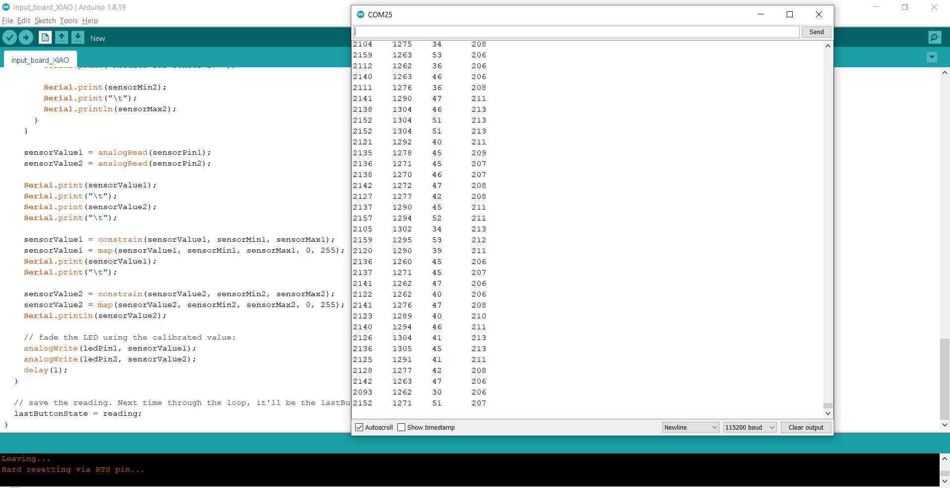
Potentiometer
Since it’s not always easy to get a linear resistance range, and I wanted to make sure that my machine was actually working the way I wanted, I first experimented with a potentiometer to get a more reliable resistance range. That way it’s easier to see if the minimum and maximum values of the resistance actually correspond to the correct positions of the stepper motors.
This is the wiring of the slide potentiometer (for my own reference):

I can actually connect the potentiometer to my input device board just like the other sensors (so to ground and data) so far which is nice; I don’t have to connect the VCC (learned about that here).
Smoothing values
I noticed with the knitted sensors already that when mapping the min and max sensor values from 0-255, the actual range seemed to be from about 130 to 255 instead of 0-255 (with about 2300-4095 as analog read values). The same was more apparent with a slide potentiometer. I think it’s because I have a 10k Ohm resistor on the board so the actual range (in case of the 10k Ohm potentiometer) is from 10k to 20k.
I tried smoothing out the values using the Smoothing example but that didn’t work at all, not even with bigger delays nor with 30 instead of 10 values in the array. I found this forum post where they advise to smooth out the values in hardware by adding capacitors. I added two capacitors from 3.3V to ground (0.1uF and 0.01uF) and a 1uF capacitor from data to ground for both sensors. This did the trick for getting more even results. It also helped in getting more accurate measurements: after adding the capacitors I didn’t have the problem anymore with the mapped range only ranging from 130 to 255.
During the last lecture I was picked by the random review generator (well, not so random anymore) so I could show my current progress and the video so far. Neil mentioned I could smooth the signal in software with a schmitt trigger or a first order low pass filter.
This simple filter can be seen in the hello.temp.45.py example, these lines in the code:
eps = 0.5 # filter time constant
filter = 0.0 # filtered value

   filter = (1-eps)*filter + eps*T
First order low pass filter:

Schmitt trigger:
Libaries:
Decoupling:
Then I tried a filter that I didn’t see before but is really super simple: just dividing by 10 then multiplying by 10. Somehow this simple filter worked the best out of all of the options. Later, when I mapped the values to a 180 degrees turn of the arm instead of a 360 degrees turn, I changed the 10 to 5.
    // Filtering the values by dividing by 10 then multiplying by 10

    Serial.print("filtered:");
    Serial.print("\t");
    sensorValue1 = sensorValue1 / 10;
    sensorValue1 = sensorValue1 * 10;
    Serial.print(sensorValue1);
    Serial.print("\t");

    sensorValue2 = sensorValue2 / 10;
    sensorValue2 = sensorValue2 * 10;
    Serial.println(sensorValue2);
Installation design
Since my first idea was a painting robot, I started making a rough prototype so I could try out all of the mechanics. It doesn’t deserve a beauty award (or stability price) but it did work.
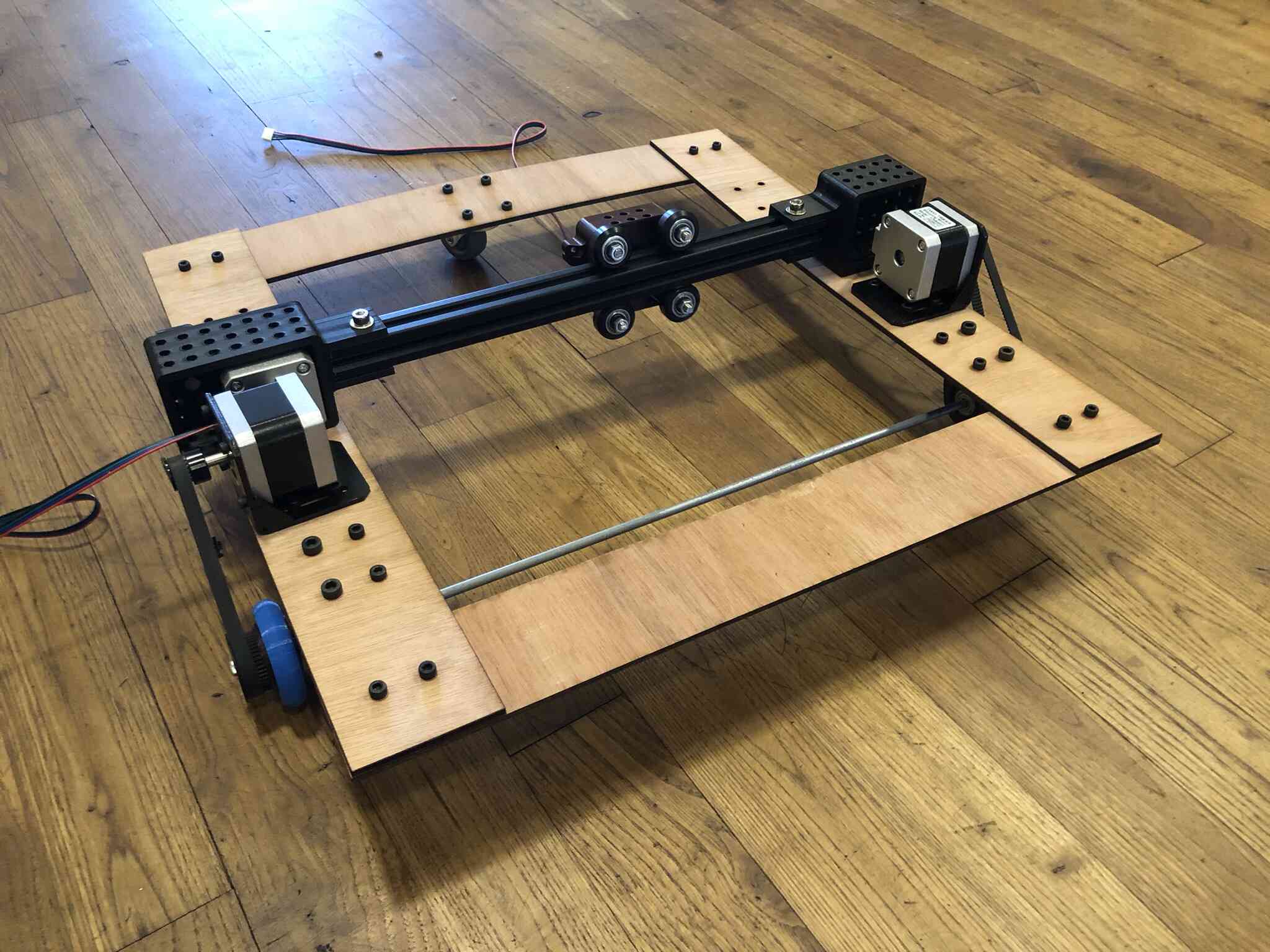
After this I decided I didn’t like it and iterated on my idea to make it more into a set canvas on which I would draw. The five bar linkage plotter gif that you’ve seen before was a big inspiration for this change of plan, so I started out with making these arms and trying them out with the same electronics I had made for the driving robot as soon as possible.
Linkage mechanism
I designed the arms for the five bar linkage system first. I wanted to reach an area of 50x70cm so I kept that in mind when determining the length of the arms. I took some rough measurements and made a cardboard prototype based on that. Here the design for the arms is seen together with the stepper motor mounts that I made after.
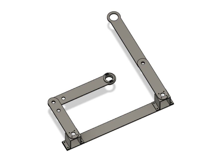
Together with Samson and someone who happened to walk into the fablab we checked the range of the first arms, which looked pretty decent. I then realized that I would have twice as much range if I placed the stepper motors in the middle of the canvas instead of at the bottom. This did complicate it a little bit I think it’s going to be worth it.
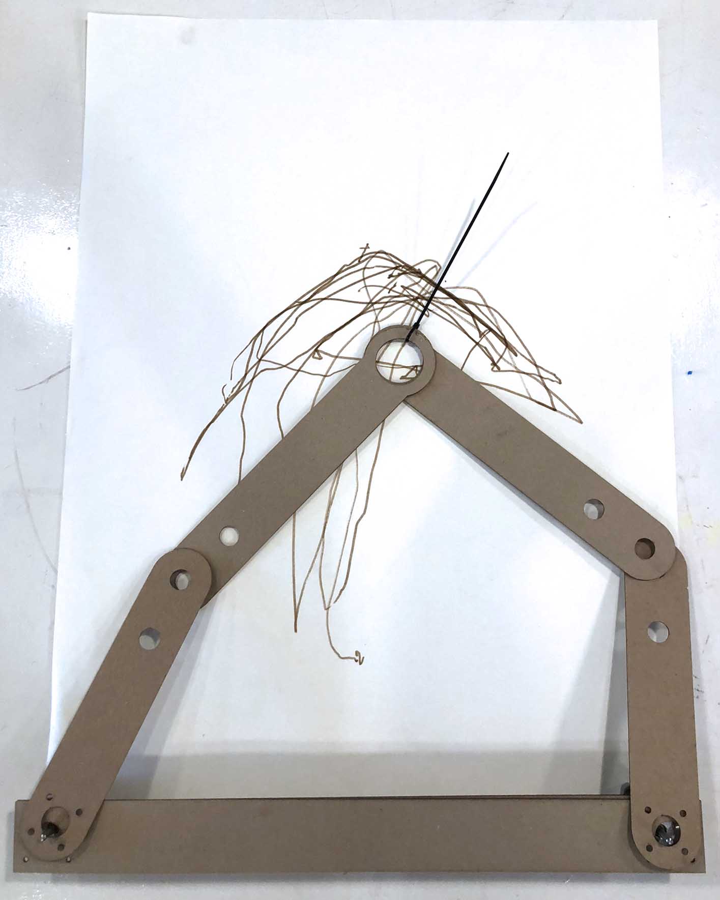
I then cut them out of 5mm transparent acrylic. I left two holes for bearings which were designed to fit the skateboard bearing I used perfectly. In the end I don’t think I’ll need the extra holes as the reach is pretty nice now. If I need to cut the arms again, I’ll probably leave them out. I also designed a simple component that I could put in the hole of the two arms, keeping them in place. I then added a component that I could slot in there that could hold a brush. This of course only works when the canvas is laying horizontally, so it wasn’t very handy. The next iteration I wanted it to snap into the holder. I also designed simple stepper motor mounts. The mount would have to be high enough so the stepstick didn’t touch anything and I would have space to route some wires. I made them 60mm high and printed them with 100% infill.
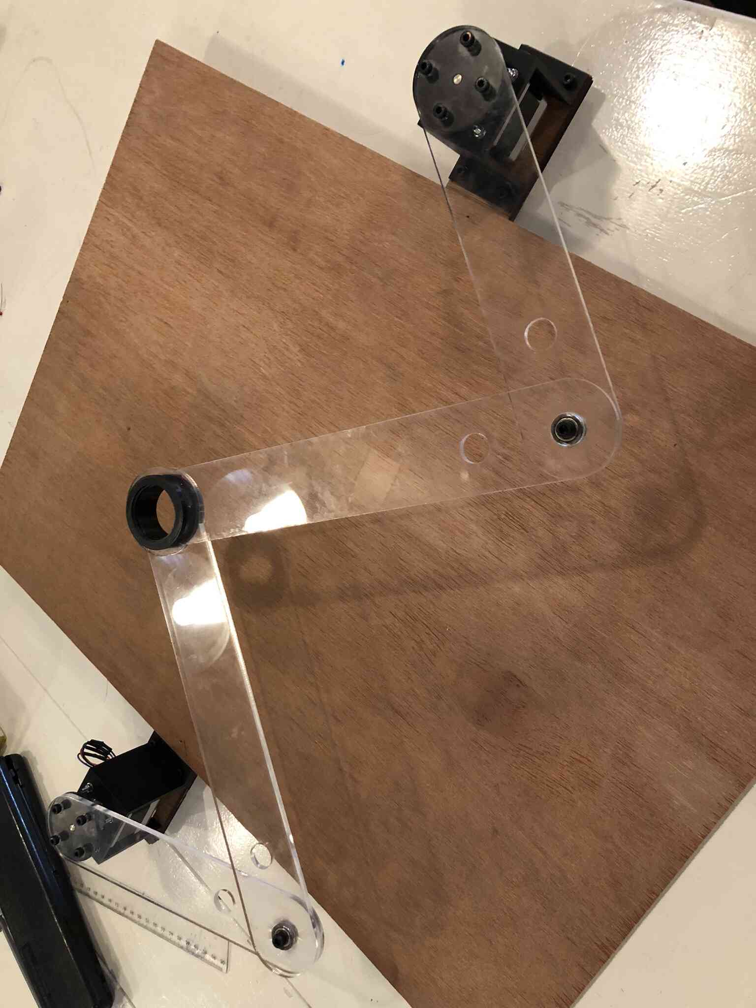
I mounted the base bar to the back of the frame with these simple brackets; I want to add a servo lifting mechanism for the entire assembly here.
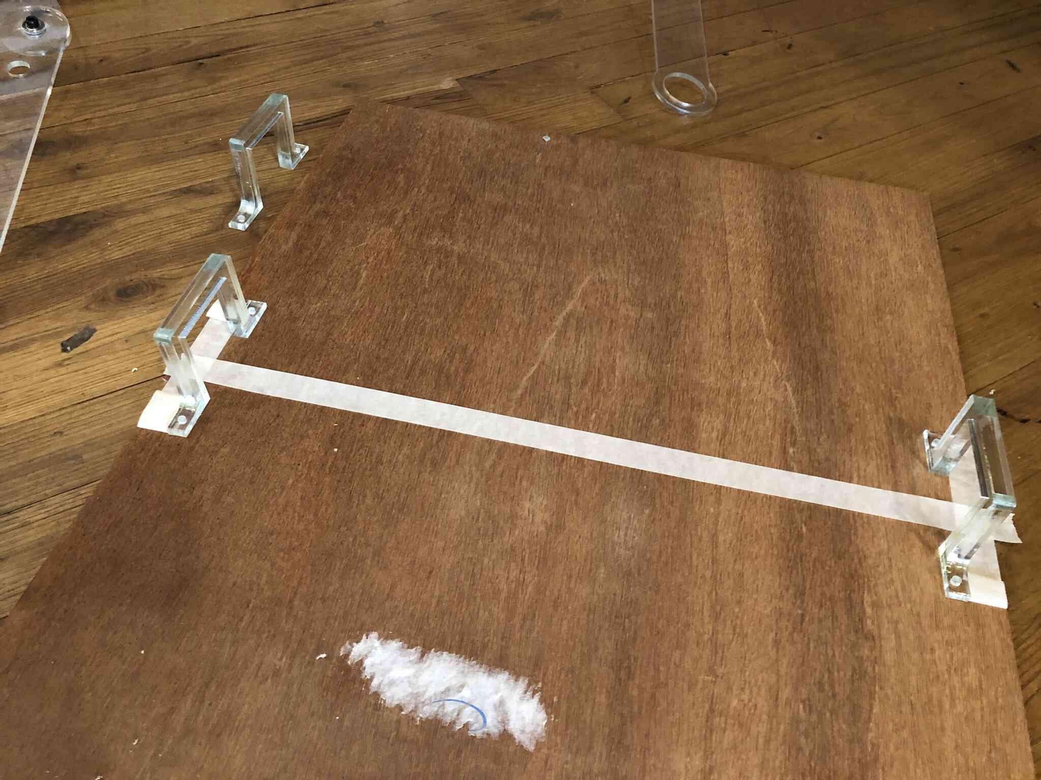
Trying it out
I tried to control the stepper motors with an LDR and a knitted sensor to compare the range and see what would happen.
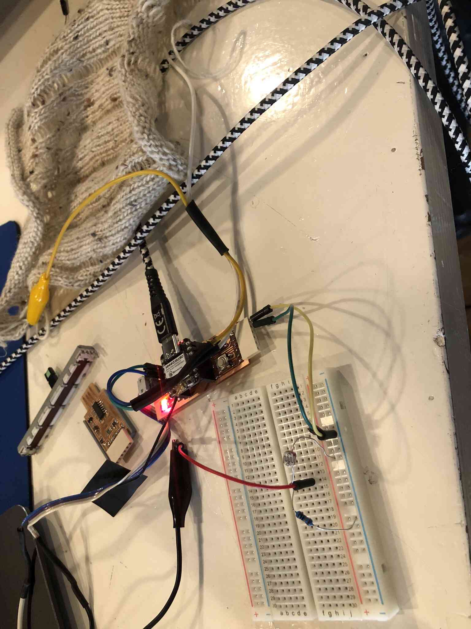
Here you can see the arms moving based on the sensor input:
The motions aren’t very clear and deliberate yet, but I’m very happy that at least it works! I think I can make the link between the interaction with the sensors and the motion of the arms clearer by programming and mapping the values in a way that makes sense. Here you can see the easle together with the linkage assembly and canvas (and plenty of glue clamps):
Automated modeling
I knew I wanted to make a nice looking installation for my painting robot, and I settled on an easle. I asked Craiyon to visualize a picture of an easle for painting in a bauhaus style that can be made in a fablab with a white background. the easle has a roll of fabric draped over the frame and there is a painting robot attached to the front (with various iterations of this prompt) as a starting point, but they’re not speaking to me yet so I’m going to design the look of the ‘easle’ myself.
I wanted to try out automated modeling in Fusion360 to design the ‘easle’ on which I will have my canvas.
I started out with this assembly of the stepper motor mounts, the bar on which I connected the stepper motors and the canvas.
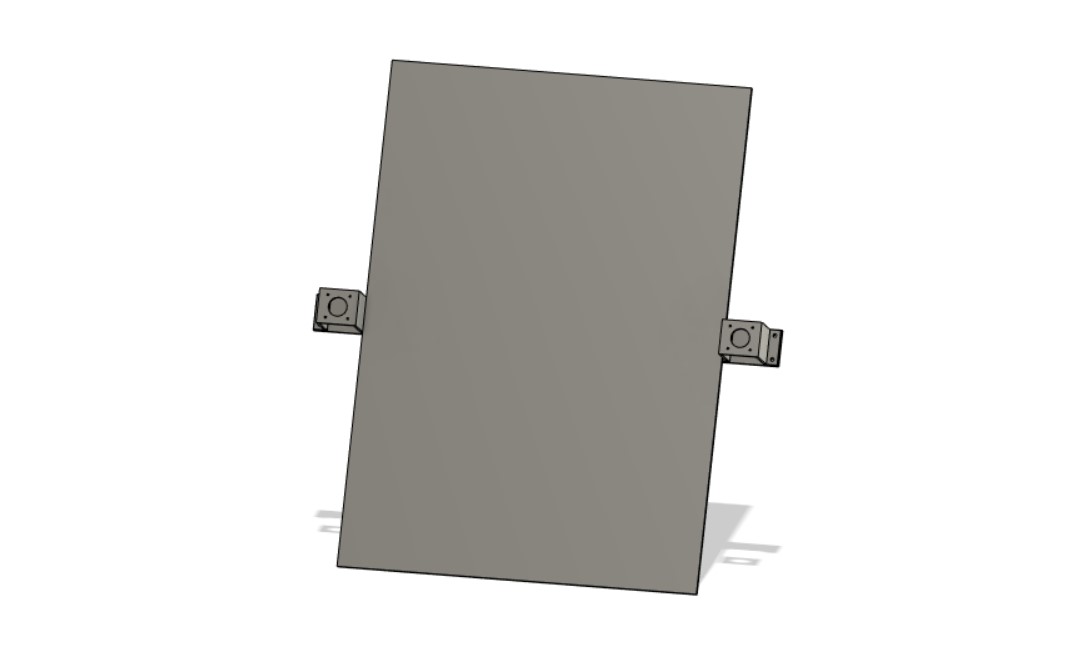
Then I added some circles that I extruded as bodies so I could select them in the automated modeling process.
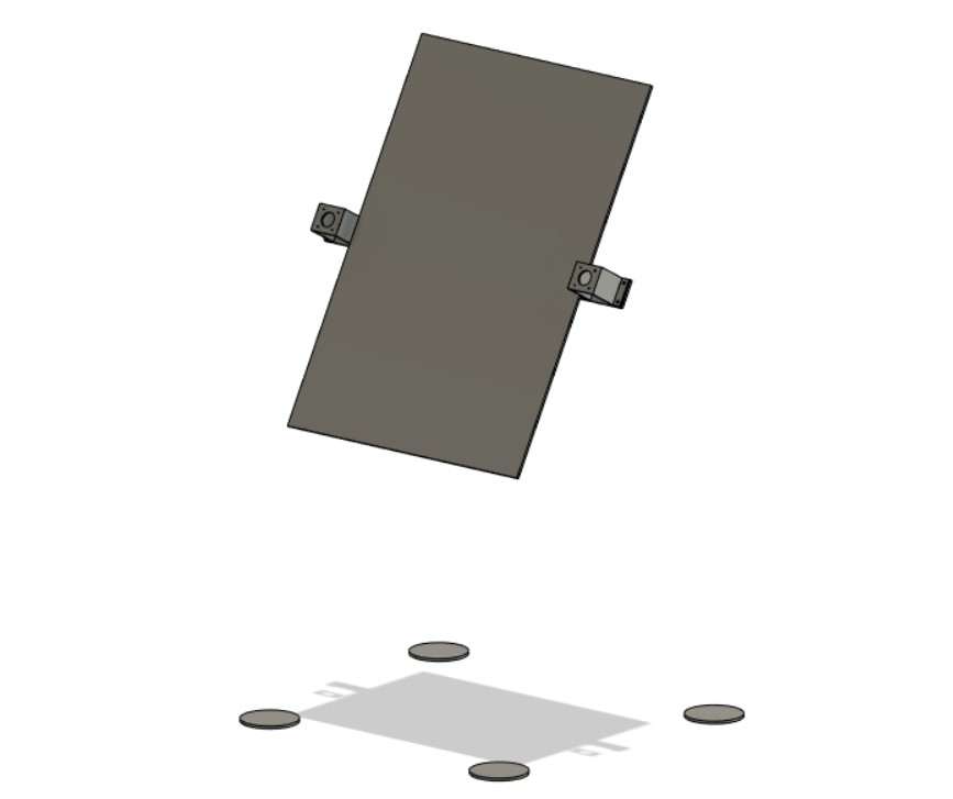
In automated modeling, you can select which faces to connect, and which bodies to avoid.
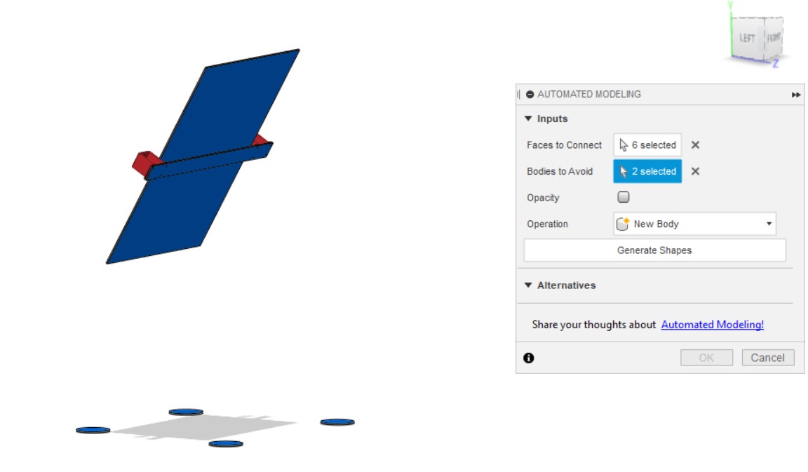
After some thinking it provides various options with a slider to make the connections thicker or thinner. You can see here that since I didn’t tell it to avoid the canvas front, so it went through.
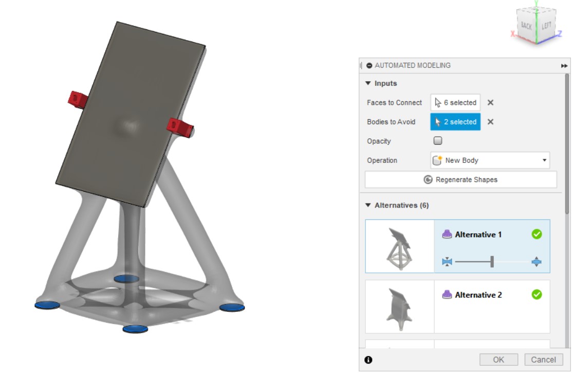
It automatically detects symmetric parts and applies symmetry to the generated model too.

I played around with some settings and added an object to avoid in the middle back of the canvas as you can see in the sped up video.
Then I saved the model as a mesh and imported it into Slicer for Fusion360 so I could transform it into a file that I could laser cut (more on how to use the software is explained during computer-controlled machining week).
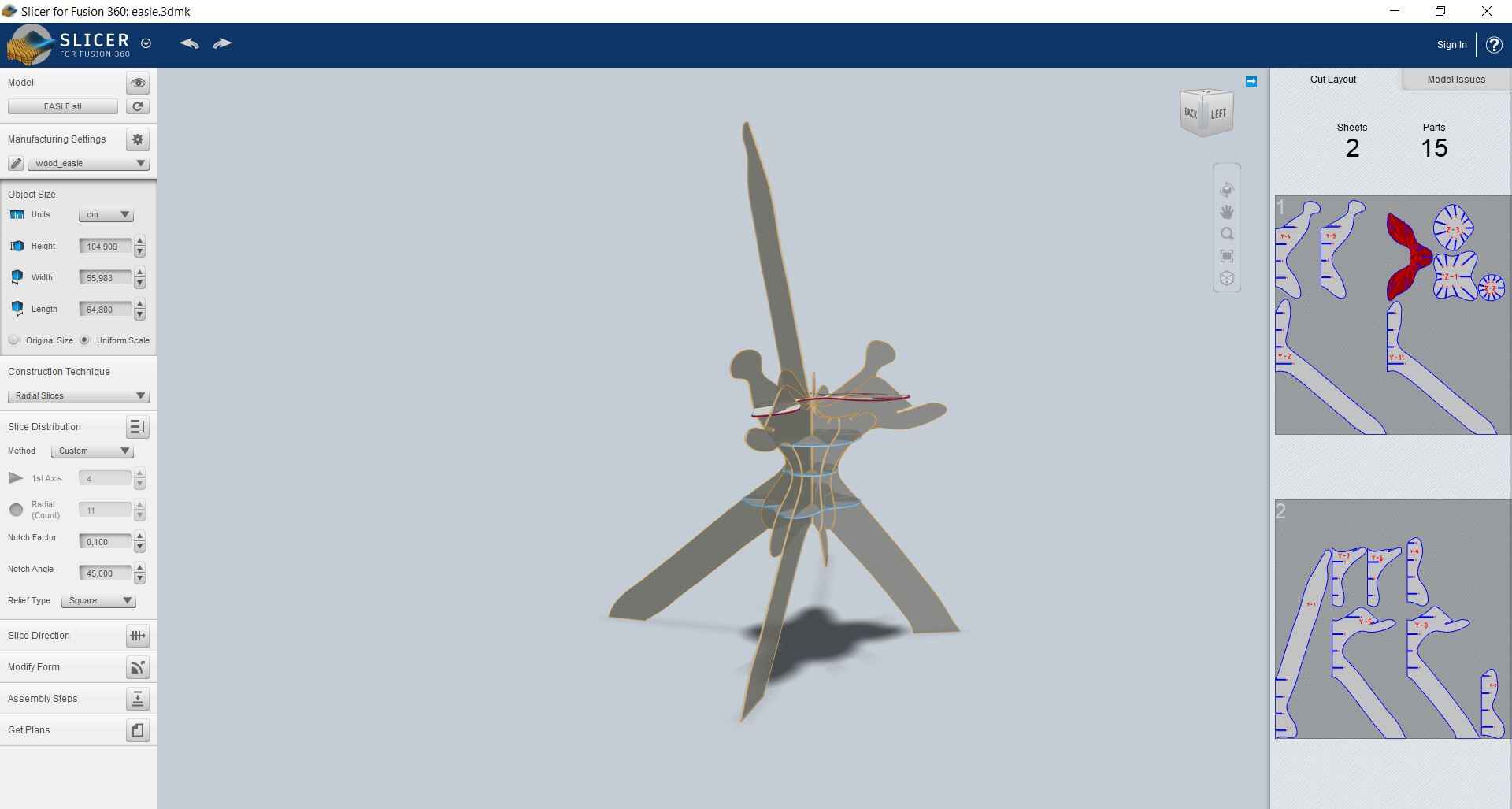
Here is the model lasercut:
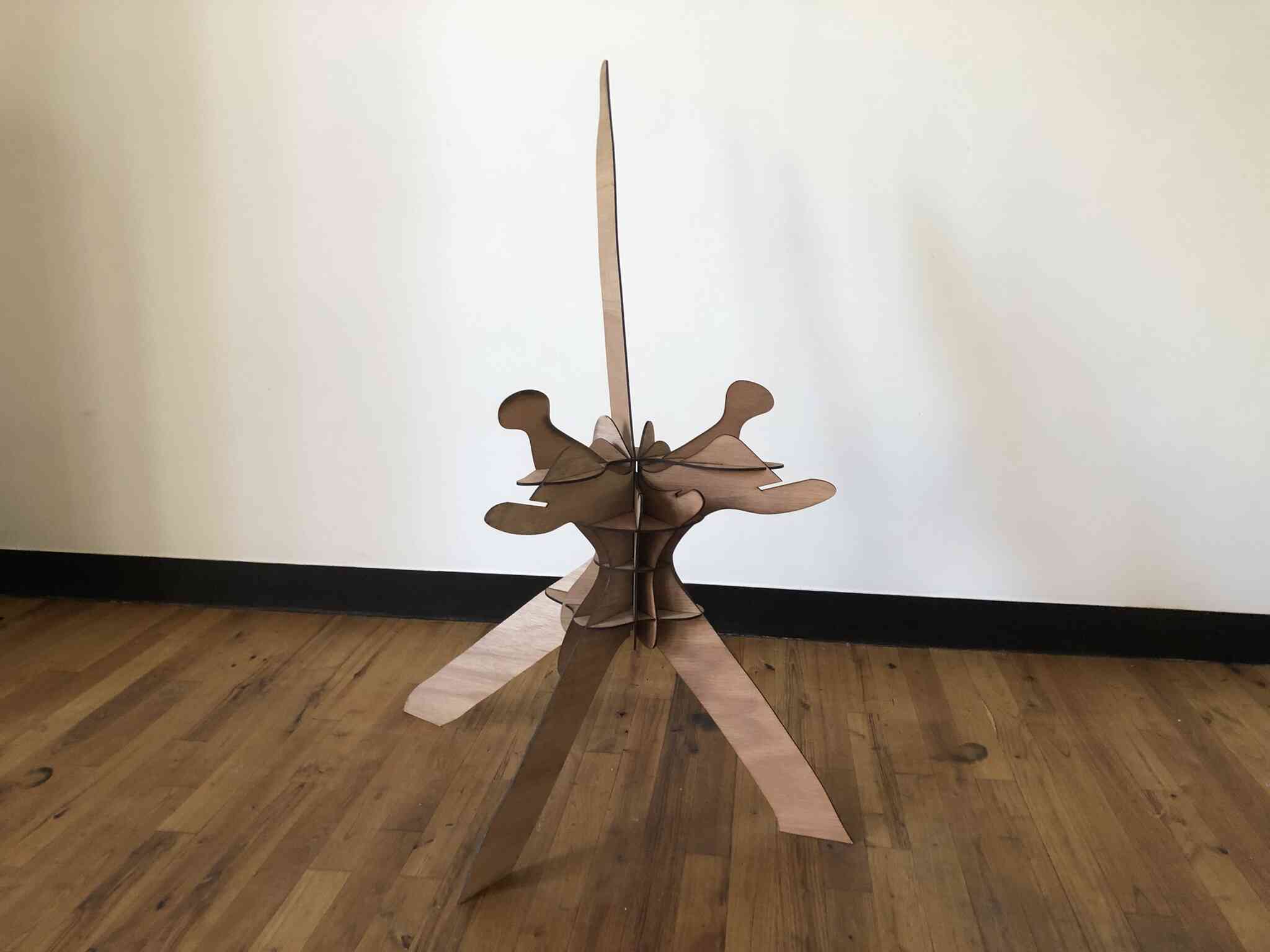
And with a canvas on top:
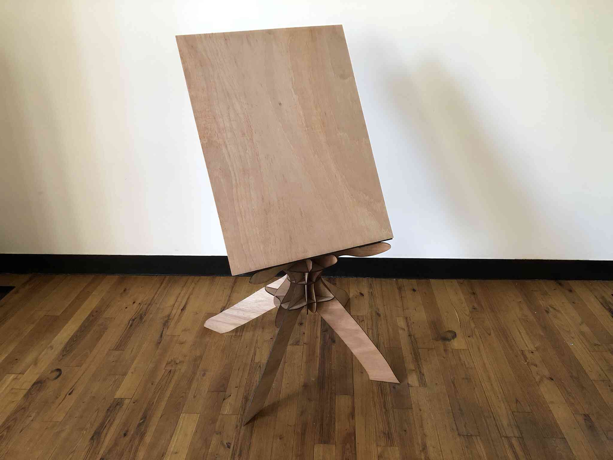
I made the easle prototype out of 3.3mm plywood. It was pretty obvious that this was too thin. I tried to make it stronger by glueing another layer to the legs. This helped a lot but it could still twist fairly easily. I also extended the top of the easle because my base bar for the linkage mechanism was too deep.
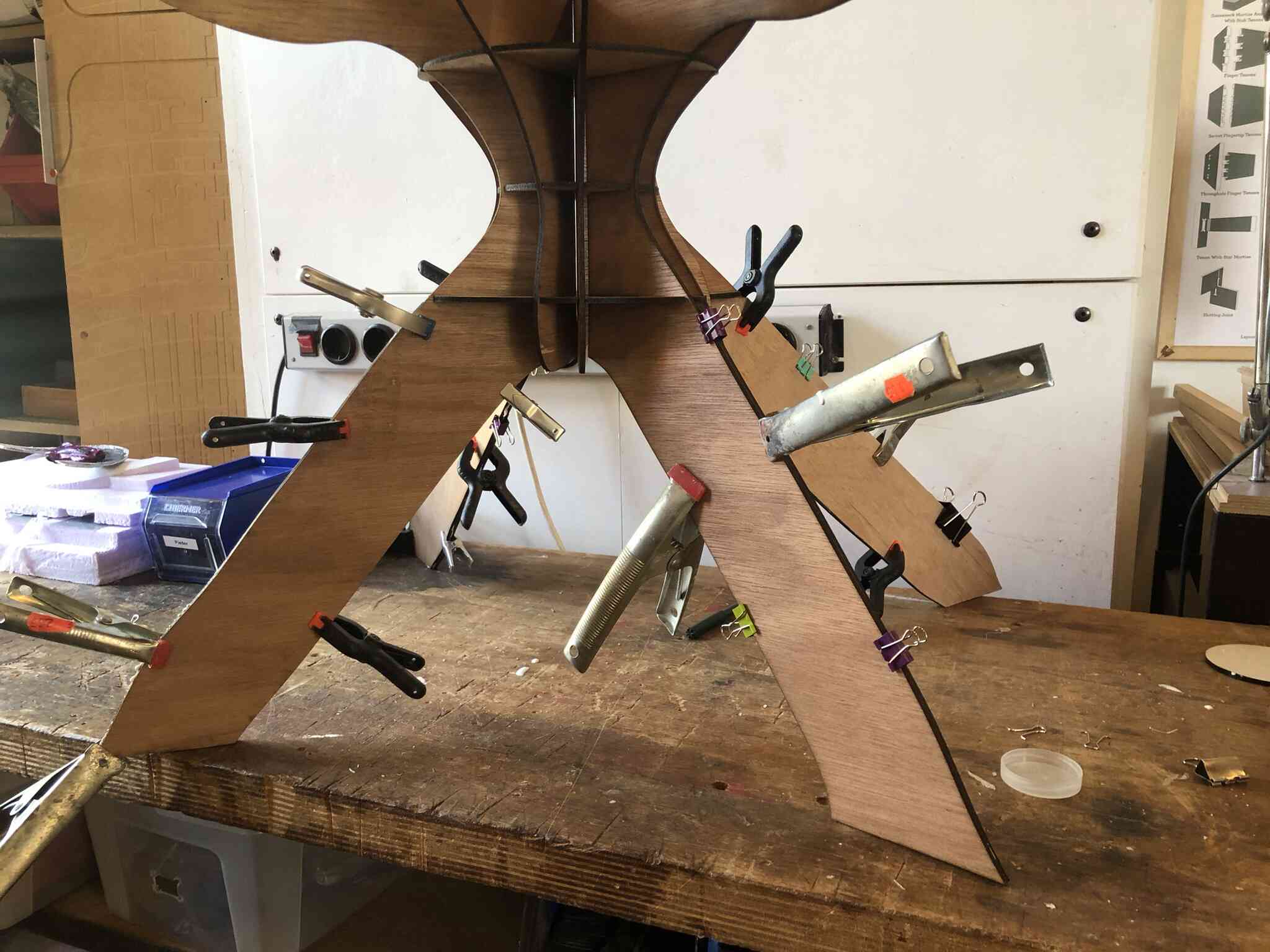
Here you can see the canvas and the easle in action together:
Iterating
When discussing my plans with Henk on the brush lifting mechanism he advised against lifting the entire bar, which was my original plan and which was why I made the brackets so that the bar could move perpendicular to the canvas. He showed me some mechanisms from the Haxidraw which were nice servo based brush lifting designs. It will be way less heavy to only lift the brush instead of the entire linkage assembly. This does mean that I need to deal with wiring to the brush module, so clear acrylic won’t be the best option anymore.
Another thing that I learned from the prototype, is that it actually isn’t possible to reach the top of the canvas when the steppers are in the middle, because the top linkage arms cannot make the angle from down to up, especially when dealing with gravity. This makes the range of the arms significantly smaller. I also noticed that since the arms are pretty long, they keep bumping into the bottom shelf that is holding the canvas (see the video below). As a solution to both of these issues, I’m going to move the stepper motors to the top of the canvas. This way I should have the full range of motion and gravity is less of an issue. Then I also don’t have to get rid of the screws connecting the linkage arms to the 3d printed stepper mount, since they won’t go over it anymore.
Since I have to add the servo motor mechanism to the brush module, I’m also going to add another servo to rotate the brush while I’m at it. That way I can create more interesting brush strokes. I’m thinking about a hack that I saw to make servo motors rotate 360 degrees but it depends on whether I’m going to just make the brush go back and forth or if I’m going to place them in an angle.
So the changes I’m going to make are:
- Make the arms opaque
- Move stepper motors to top of frame
- Make arms slightly longer
- Adapt brush module to integrate servo motors
- Should be possible to rotate and fix the brush manually
- Integrate wiring to the back of the frame in the arms
- Changed the mapped positions from full rotation to 180 degrees rotation since it’s the same range but reversed; that way the servo cable can’t get stuck in the gears
New easle
I spent two days figuring out how to make the new easle, and somewhere along the way I completely forgot that I had planned to move the arms to the top of the machine and also the reason why I planned that. I moved the arms to the bottom so the weight would be at the bottom of the easle instead of at the top, which would make the installation more stable. This also made it easier to mount the servo motors to the frame.
I went back and forth with what I wanted; I needed to find a way to make an easle that would be possible to slice or be made directly in Fusion. I prefer using Slicer because then I can use automated modeling which creates a kind of silhouet that I would like. However it does make it harder to connect all of the moving parts to the easle and secure the canvas onto the easle.

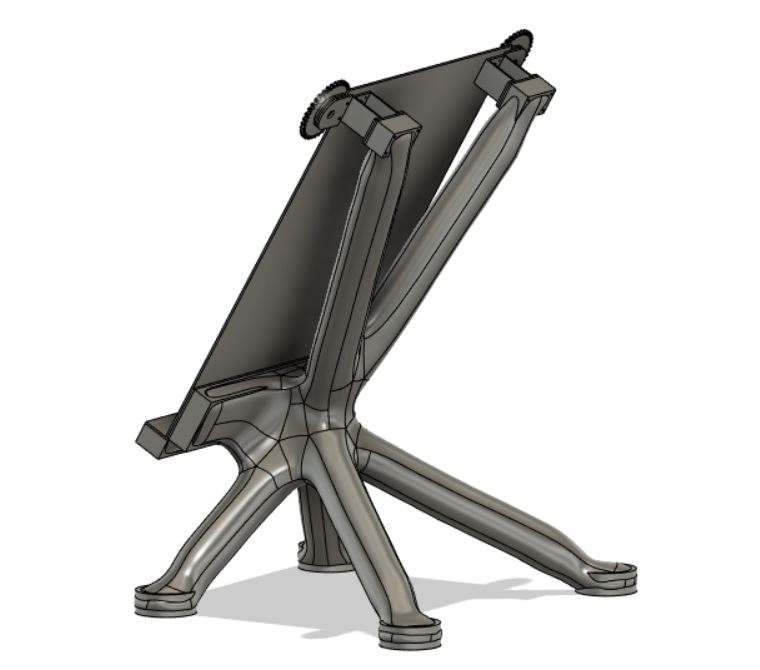
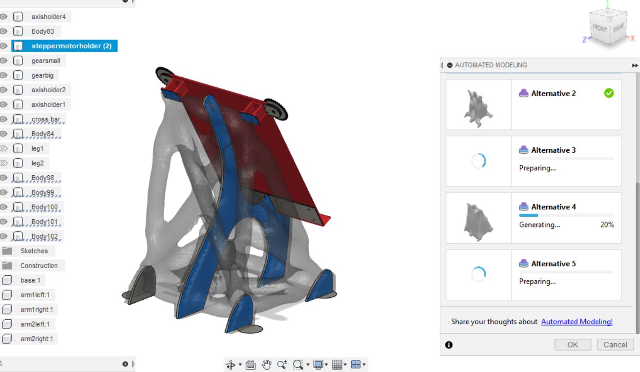
I figured if I have a narrow bar like before that I can attach the motors to perpendicularly, that would be pretty stable. After this I moved the bar to the back, so I would have a canvas space without restrictions for the arms to move below the canvas, and to connect the motors out of sight.
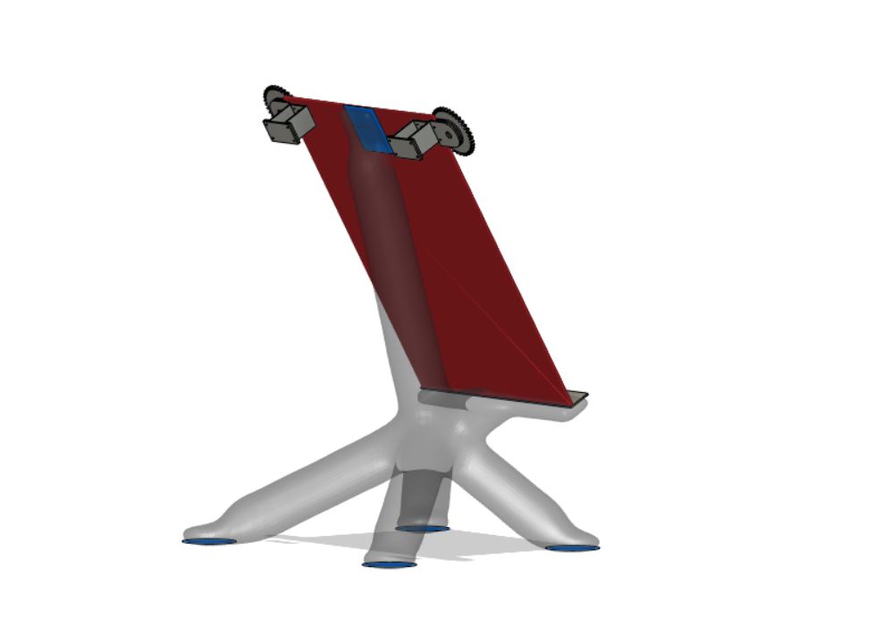
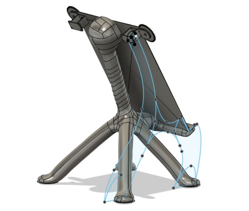
I settled on this design:
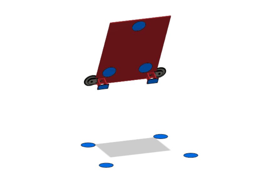
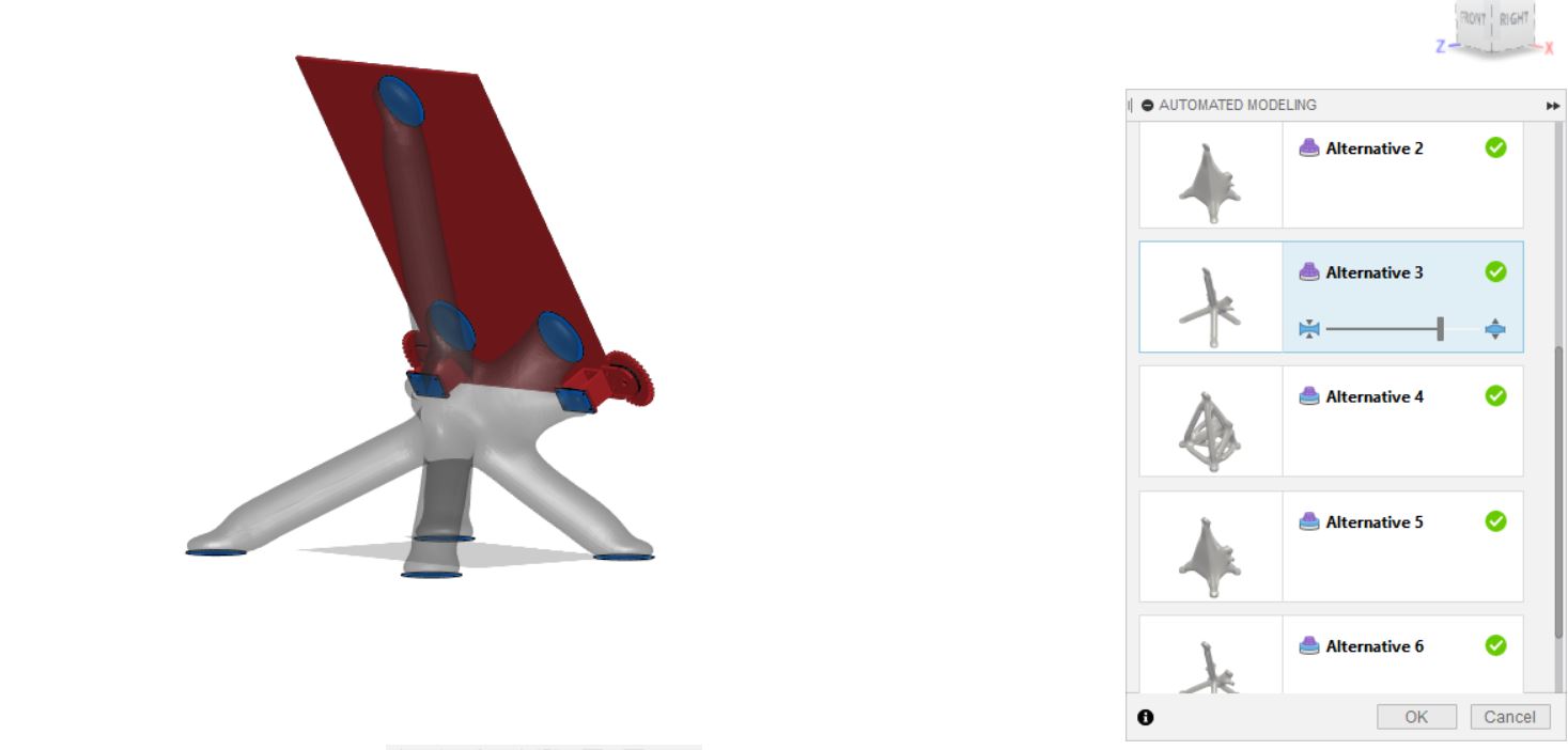
CNC milling
Since the current easle is very flexible and weak, I’m going to make another one but this time out of thicker plywood which I’m going to mill. We had a slab of 200x90cm plywood with a thickness of 9mm so I used that. It’s a bit darker than regular plywood which I liked.Just like the previous easle design, I used Slicer for Fusion360 to translate the 3D model into 2D vectors for machining. This is the design I settled on (the floating parts will be deleted).
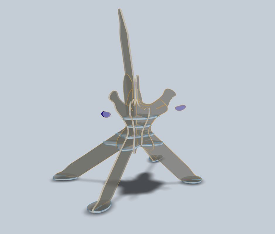
When I started the milling the first piece got loose. All of the tabs for that part were in the slots so it couldn’t hold on to anything. I think it went wrong when I recalculated some toolpaths, because I double checked and all of the other parts had their tabs in the correct spots.
When milling the plywood I learned that it wasn’t great quality. It splinters a lot. I decreased the feedrate to 40mm/s which made a big difference.
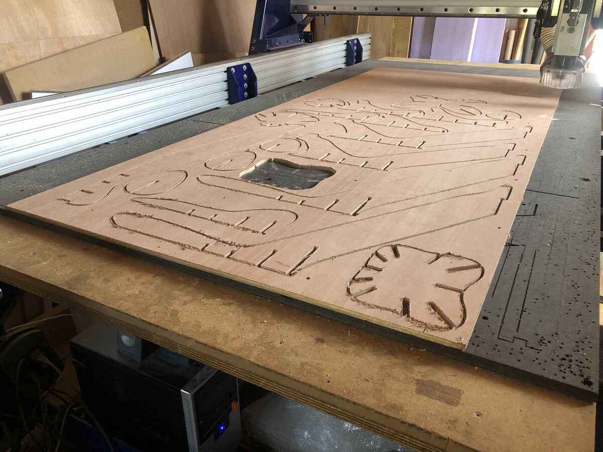
After the milling job was done, I checked the width of the slots I had milled in various places. In most places it wouldn’t be enough to get a comfortable press-fit, so I milled another pass along all of the parts with a kerf offset of -0.5mm (with a pass depth of the material thickness). I measured again and felt pretty confident that the slots would be big enough and I was very happy with myself that I learned from the mistake I made during the CNC week.
Force-fit
Sadly the next day, after 4 hours of sanding, my confidence in the slots got completely crushed. I had to resort to violence to make it fit, which damaged the sides of the already not-so-great wood. I also snapped the wood in 3 different places. I glued it, because I don’t have time to mill the parts again, and because I probably also won’t get the parts out now anyway.
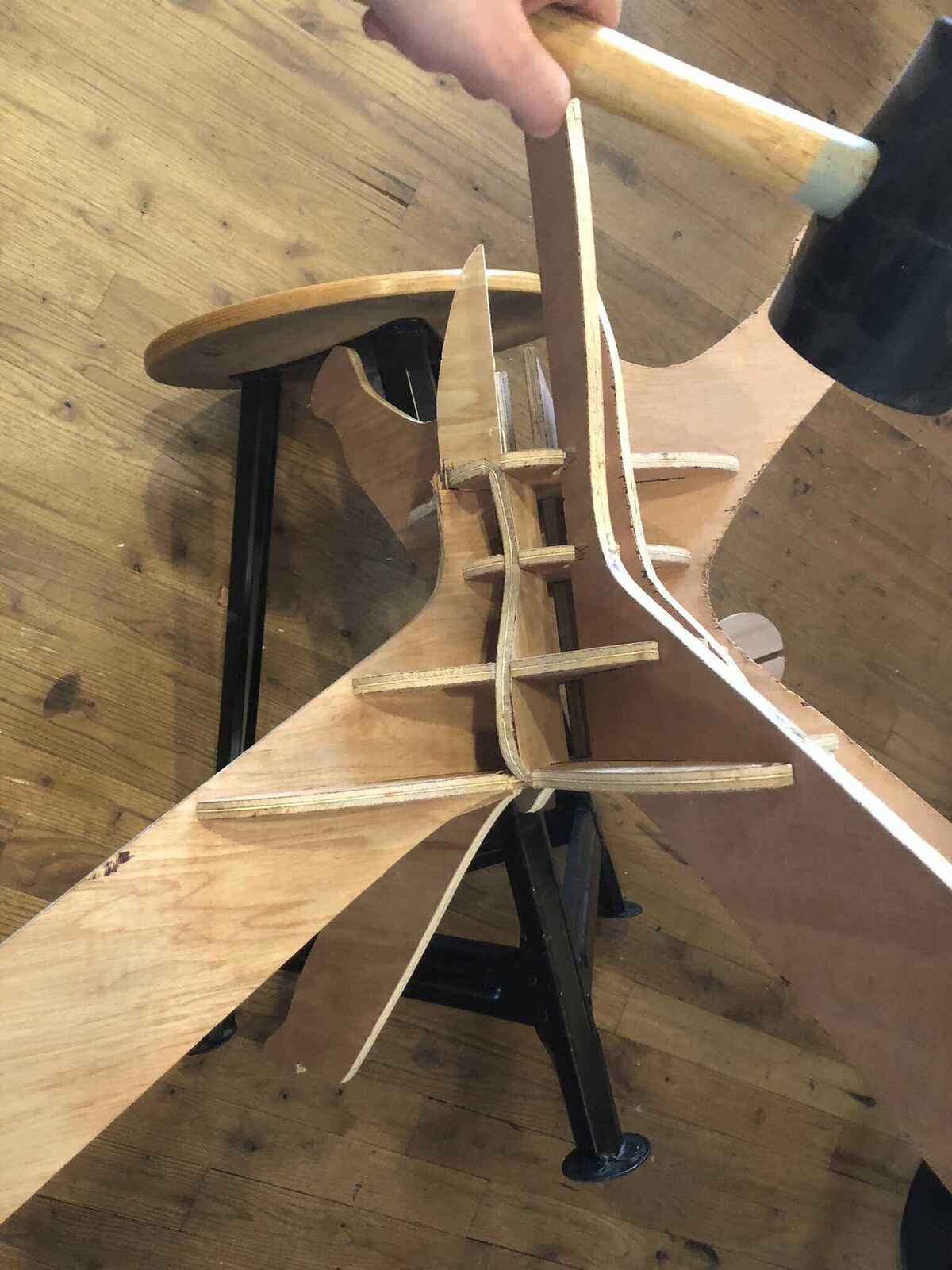
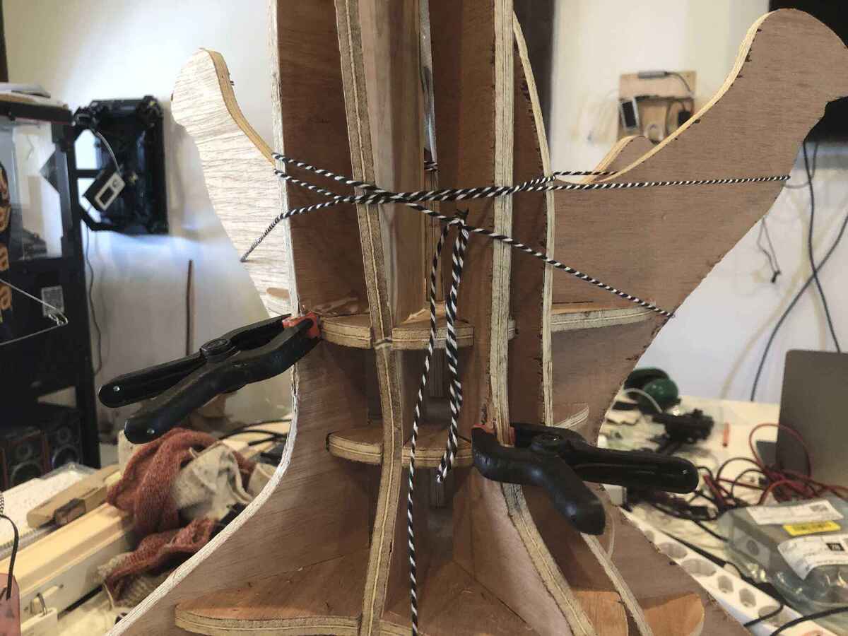
Input easle
In the last weeks I was still doubting how to make the input device: I wanted to make a wearable at first, which is why I made mittens during wildcard week, but I also learned that week that the motion of the hand wasn’t enough to get a good measurable contrast. After I made the big easle I had some plywood left, and I figured I could make another smaller easle out of it for the textiles specifically. I thought it would make more sense visually to have two installations where one controls the other, and it would be more inviting to interact with it than with a wearable. I designed this easle in a similar way to the bigger easle, with automated modeling and trial and error. I had to make sure the parts would fit in the plywood I had left, so it couldn’t be too big or intricate.
First I designed one where the canvas was horizontal. Then I changed that to an angle of 30 degrees. After that I figured it would be stronger and easier to slice if the frame wasn’t part of the easle.
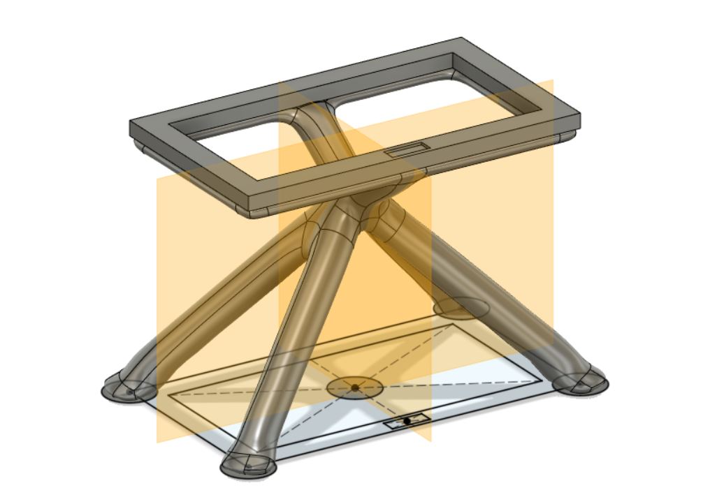
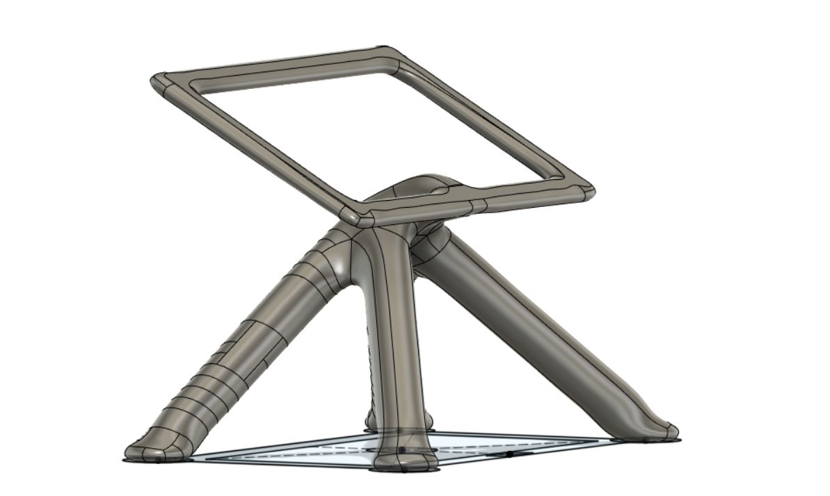
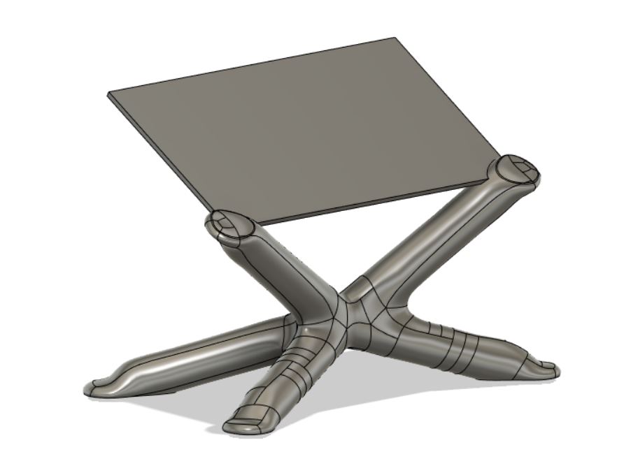
I figured that two points of contact with the frame wouldn’t be very strong either, so I added a third in the middle. I also started thinking about how to design the frame to leave room for buttons.
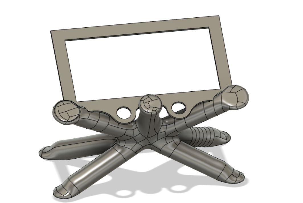
Then I exported the easle body as a mesh and imported it into Slicer for Fusion360.
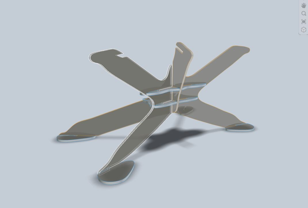
Milling went well; I used the same settings as before except for the kerf offset: I set this to -0.8mm so I wouldn’t have the same nightmare press-fit as before. I would rather assemble the easle with wood glue than have to spend hours on assembly again. Here is the easle assembled:
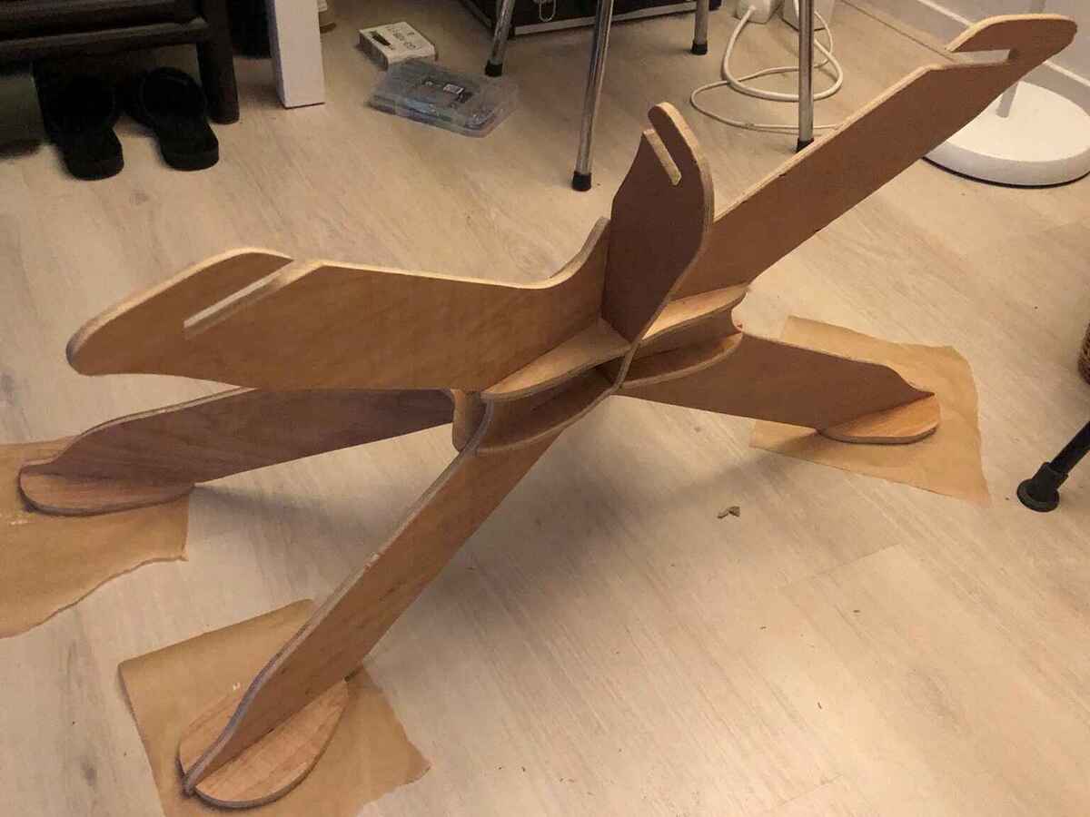
E-textiles
Knitted sensors
I made knitted sensors during the wildcard week. The documentation on that can be found there. The ones I made during wildcard week were a bit on the small side and I wanted a better resistance range, which I found was easier when knitting on a coarse knitting machine like the Brother 260. I made more after that week at my job at the HKU textile workshop where we have that machine; the techniques remain the same as during wildcard week. I also used a small knitting mill that you have to crank by hand.

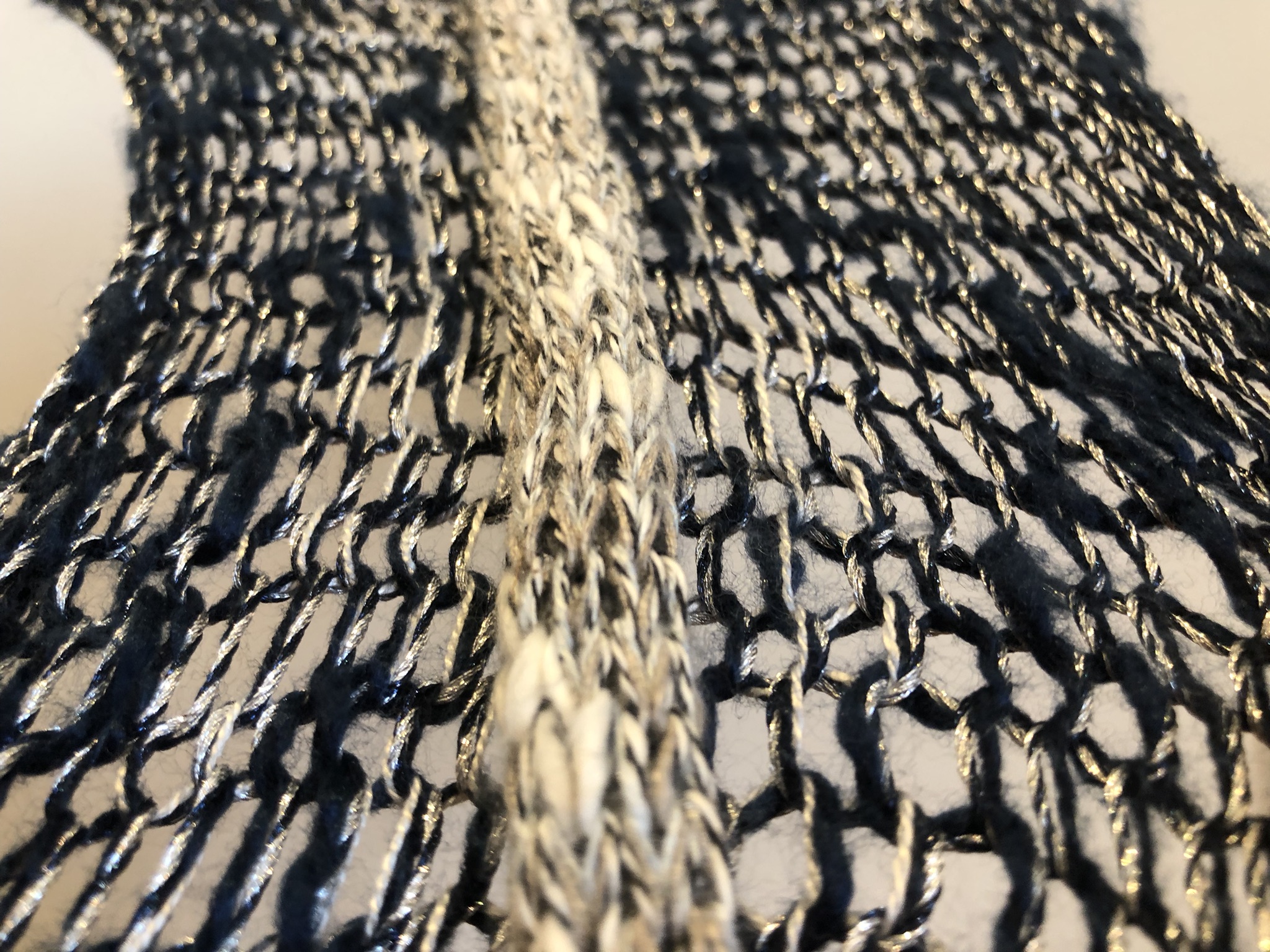
Push button
On my input device PCB, I had a push button integrated to start calibration of the knitted sensors. This was fine while developing the installation, but I needed a more elegant way to push the button once the PCB was hidden somewhere. Since I made an easle for the e-textiles sensors, I only needed to find a spot to integrate a button nicely. I decided to make it part of the frame to which I attached the e-textiles. I also added another push button to toggle the position of the pen in the brush module. I made the warped text (BRUSH and CALIBRATE) in Illustrator with the Warp Text tool (Object > Envelop Distort > Make with Warp).
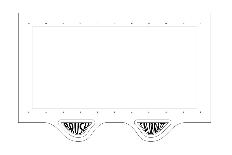
I engraved unbleached cotton fabric and laser cut the pattern outline for both buttons.

I glued the pattern parts to the plywood top part of the button with wood glue. First I planned on fusing copper fabric to the engraved pattern piece, but I didn’t want it to be visible on the outside, so I fused it to some white felt instead. I soldered jumper wires to each piece of copper fabric.
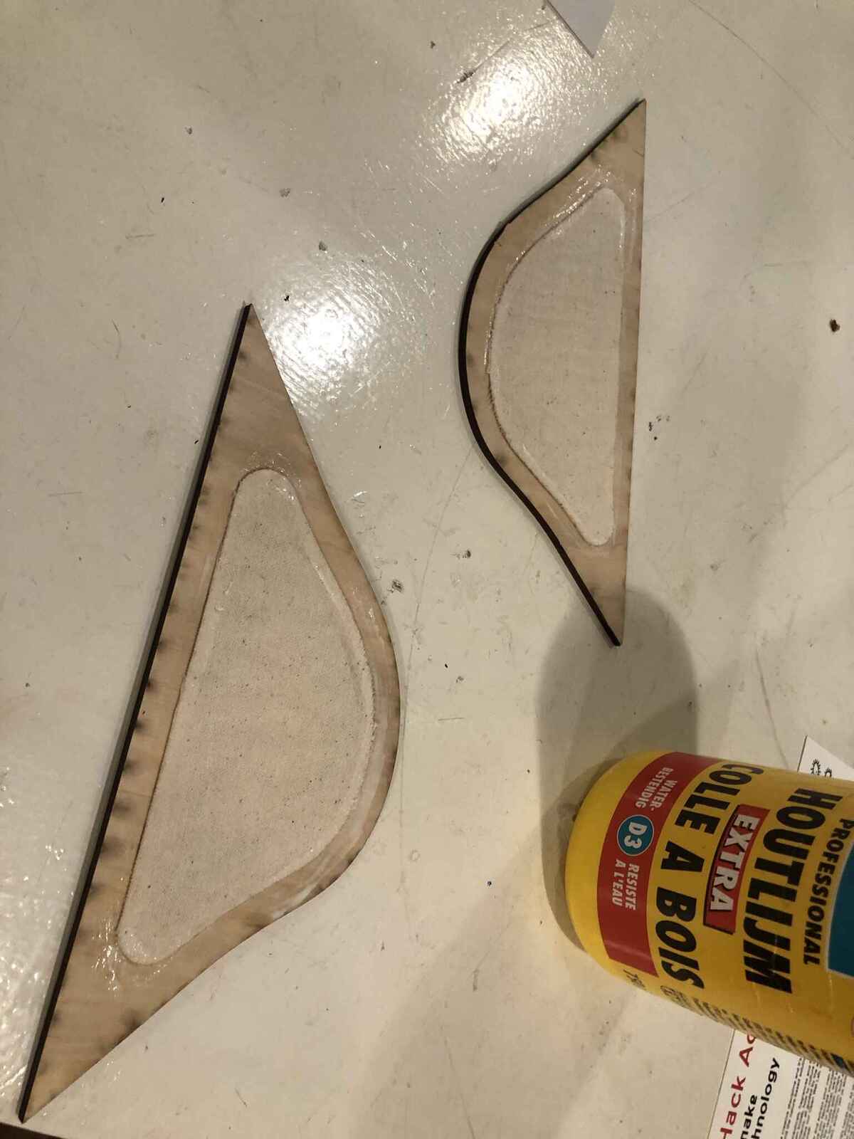
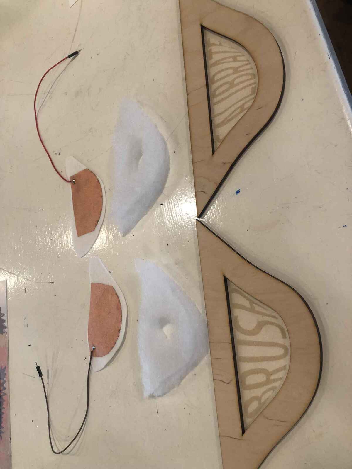
On the frame itself I glued the other side of copper fabric; I drilled a hole through it to route the jumper wires. In between the layers of copper fabric I used Fiberfill fabric with a hole cut in the middle to keep the copper fabric apart. When you push the button, the copper fabrics make contact and a push is registered just like with a regular push button. I used a lot of glue clamps to glue both assemblies together. It would have been better if the button was mounted with screws, but I didn’t have screw holes and I liked the clean look (so let’s hope I don’t have to troubleshoot them).
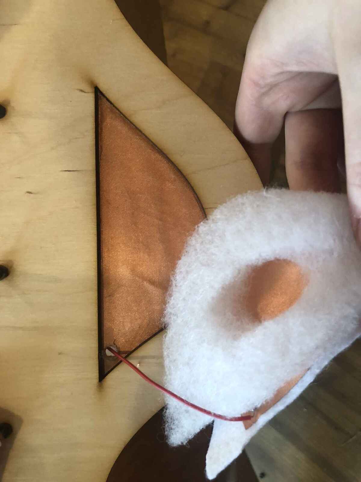
Links:
- https://www.kobakant.at/DIY/?p=6835
- https://www.kobakant.at/DIY/?p=1781
- https://www.kobakant.at/DIY/?p=2028
Gear design
Designing and printing the stepper gears went pretty smoothly, except for the fact that I forgot to add a slot for a nut to attach the print to the stepper motor shaft. I used a 4mm grub screw instead that I screwed in (with quite some effort).
Gear spacer
To connect the big gear to the smaller stepper gear, I made a simple laser cut part with bearings press-fit in them. I cut slots in the canvas so I would be able to move around the part to get a good alignment of the gears.
When I mounted the gear I learned that slot was too small and the center of the gear was too far from the small gear (even though I tested it before and it worked fine). Since I wasn’t a big fan of how I made this part, I made it again.
I modified it directly in Lightburn and cut it again, this time with more layers to be able to have the big gear higher without just stacking gears like I had done before. It looks a bit messy because this plywood really didn’t want to be lasercut all the way through so the edges are a bit burnt, but it’s going to be obscured by the big gear anyway.
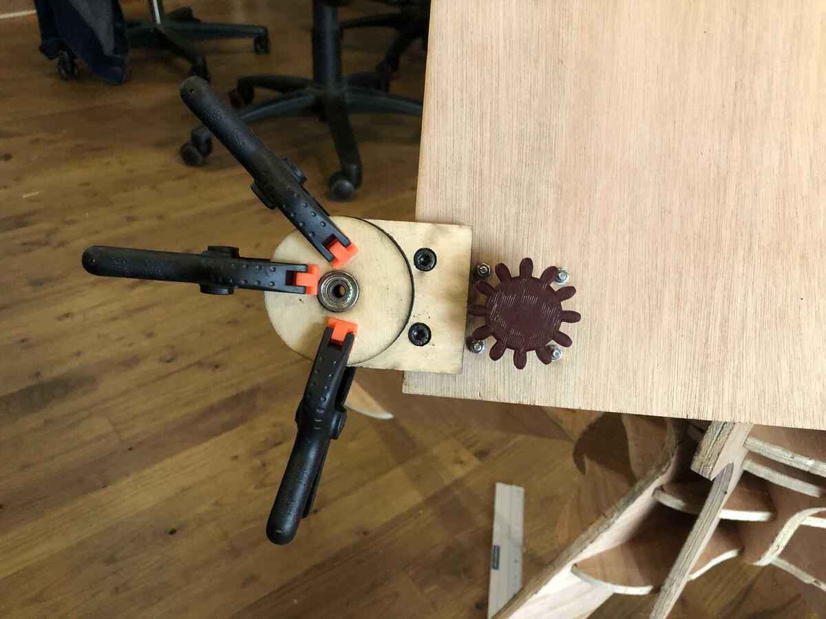
Brush module
Since I wouldn’t have a linkage lifting mechanism in the back anymore but only a brush lifting mechanism, I had to redesign the brush holder. I used these linear servo actuator mini version STEP files as a starting point. I chose to use the SG90 Micro Servo instead of the heavier high torque MG995 since it’s way smaller and lighter (9 grams) and more than strong enough to lift a brush. I built the brush mechanism around the bracket (on the left) and around the pusher (on the right).
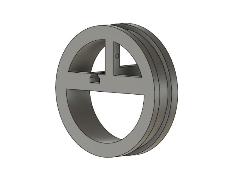
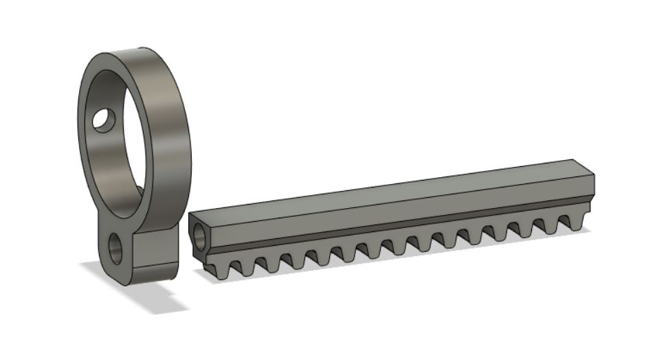
This is what it looks like printed:
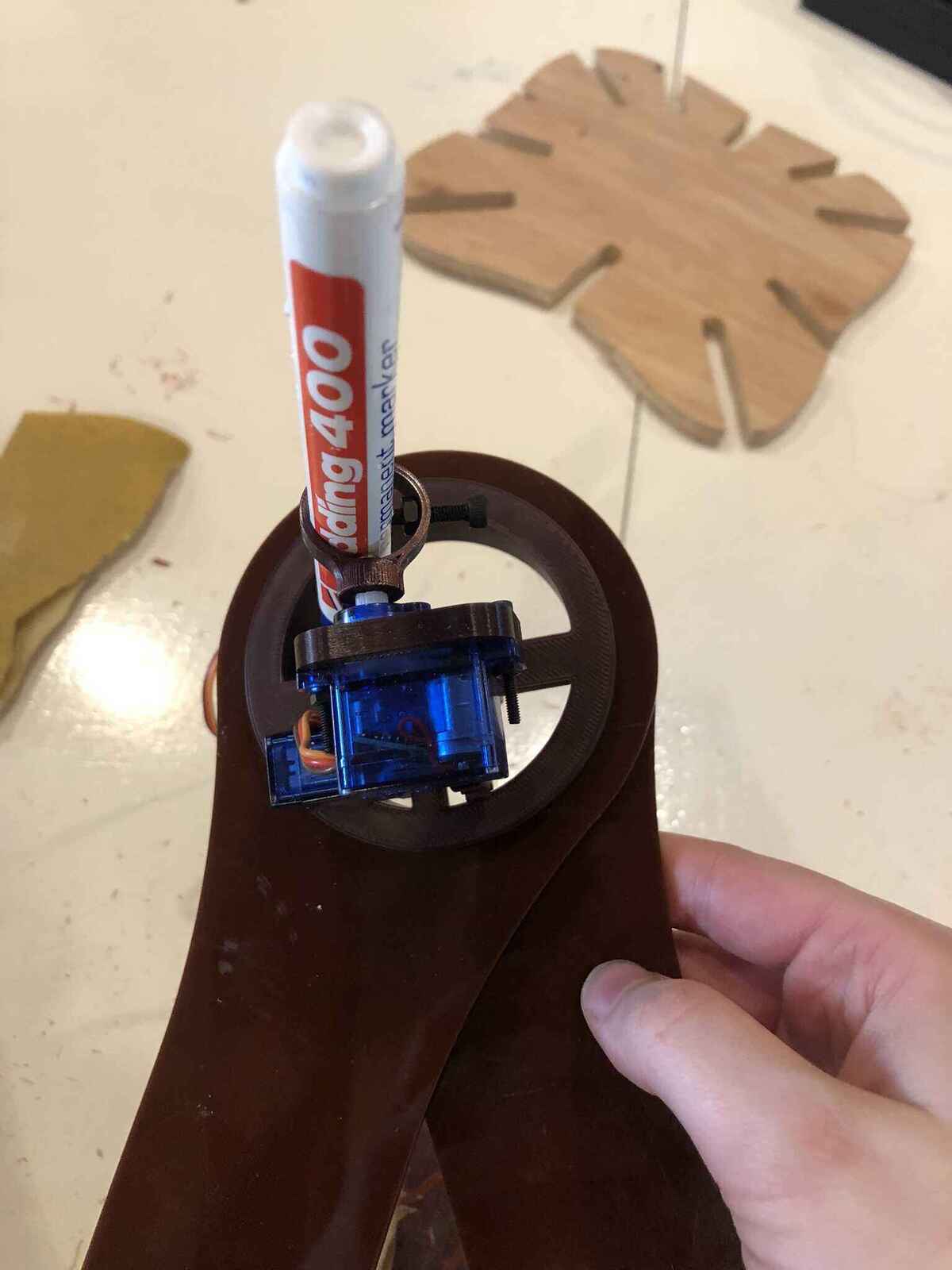
I would still like to have a more complex brush stroke than what I have now, with a brush that can also move back and forth. I started on it already and made a version of the pusher on the brush module that would hold another servo motor. However I dropped it when I was struggling with weight reduction. I made this prototype when I was still making a driving machine with a high torque servo.
Arm and gear
I was thinking about how to connect the big gear to the arms: I didn’t like just bolting them together, because I like the uninterrupted shape of the gear. I thought about making a 3D printed gear where I could slide the lasercut arm in, but that would take a really long time to print (times 2) and it doesn’t necessarily make it look nicer. The print would also probably have to be printed in two parts since the overhang would make it impossible to get good print results. Then the parts would have to be mounted together again making it unnecessarily complicated.
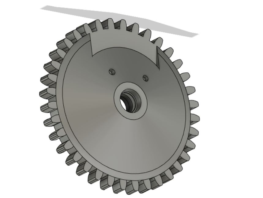
I decided to go for a very simple but effective solution: I cut the arms again but combined with the big gear shape. I don’t want to use the gear part, I just don’t want the shape to be interrupted. I bonded the gear part to the other gears with acetone like I had done before.
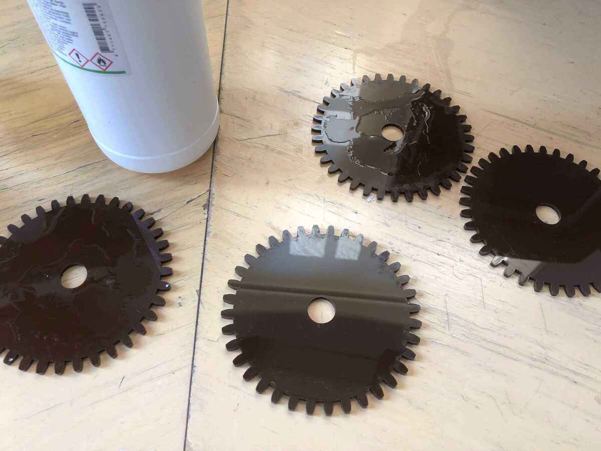
Weight reduction
Gravitational torque
I calculated gravitational torque after the first prototype demonstrated that the arms were too heavy for the motors I was using.
The holding torque of the 17HS4401 stepper motors is 42Ncm (60oz.in). This is about 4,282kgcm. I want to extend the arms closest to the motor to 20cm, which means that the holding weight at the end of the arms is going to be 4282/20=214,1 grams. I weighted one arm plus the previous brush module which was about 100 grams, so that should be fine. However since the steppers are mounted in a steep angle I also have to deal with gravity. There is also the other arm that pulls on the other motor so that’s another 100 grams (even though there is another stepper motor that helps holding it). To be sure I want to be able to hold at least double that so 400 grams.
To calculate gravitational torque I can use this formula (found here)
Tgravity = m * g * r
0,49,810,2= 0,7848 Tgravity in Nm which is 78,48 Ncm
To get that torque I need a ratio of about 2 between a smaller gear on the motor and a bigger gear attached to the arm. After this I realized I wanted the arms to be longer to reach a height of 60cm. This means they should be 24cm and 36cm instead. Recalculating the holding weight results in 178 grams, which I will keep in mind when designing the arms.
- https://www.omnicalculator.com/physics/gear-ratio
- https://engineering.stackexchange.com/questions/42512/mechanically-increase-motor-torque
Trials
For the first iteration I used 5mm transparent acrylic, but it was pretty heavy. I also planned on wiring the servo motor wires under the arms and I had to bond some parts so transparent material didn’t really make sense. I also kept running into weight and torque issues so I tried different ways to make it lighter.
I found some leftover dark brown acrylic (3.2mm) that matched the color of the 3D prints I made and also looked nice with the darker plywood that I was using, so I tried that out. 3.2mm was pretty flimsy so I made it stronger with some acrylic glued perpendicularly. I later removed this again because it added a lot of weight and the strength seemed fine enough on its own. I cut out the middle part of the top arms to lose another big part of the weight.
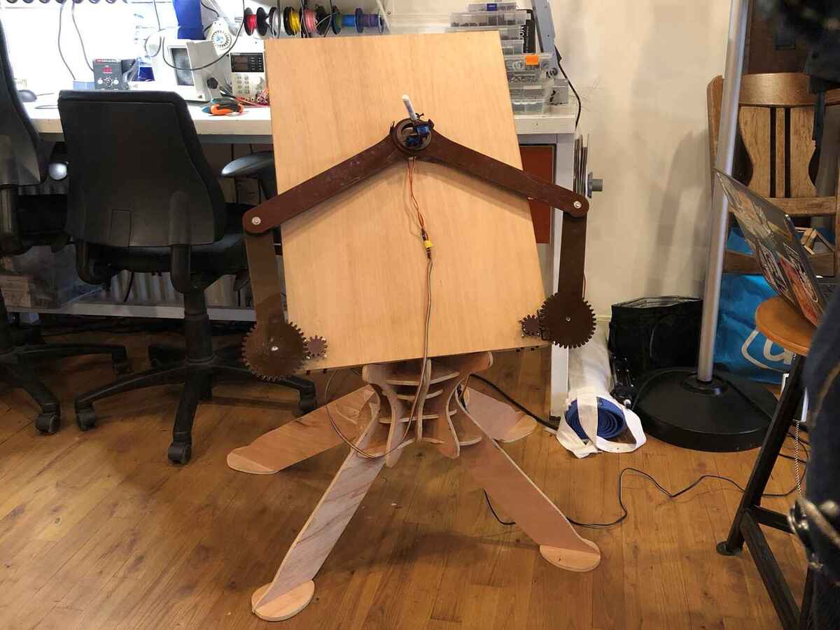
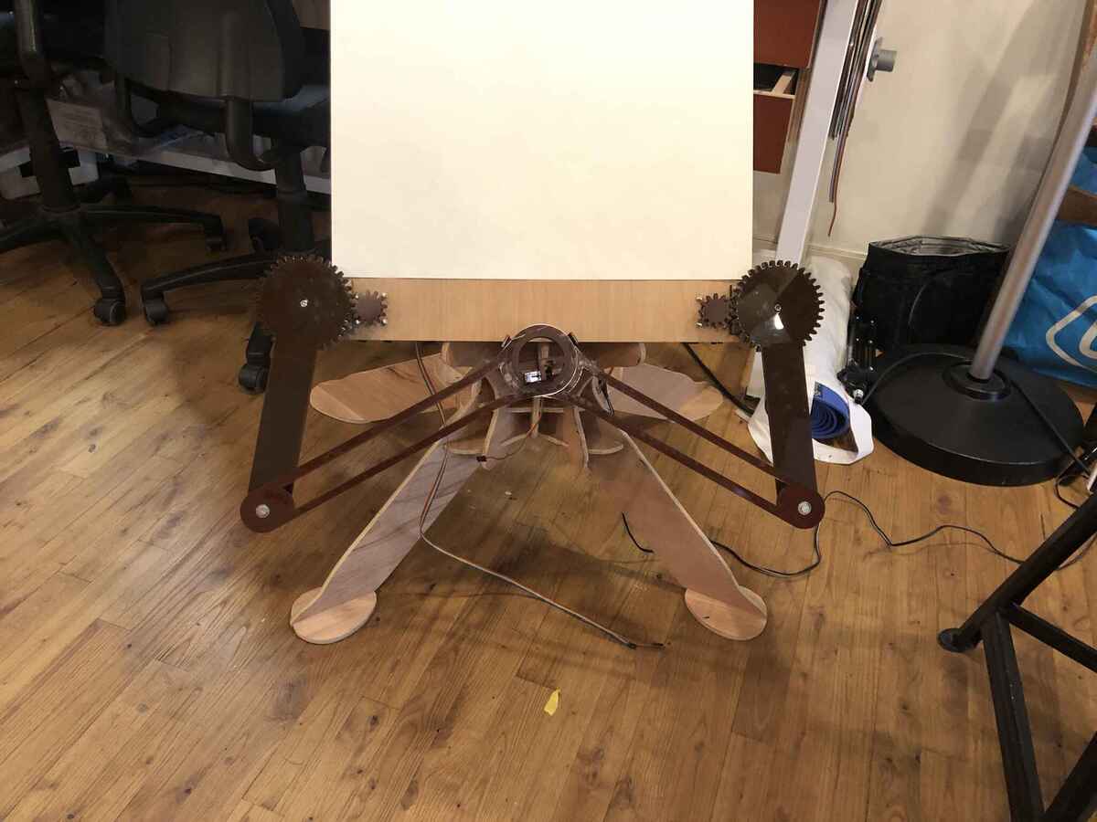
I also tried this 3mm plywood, but the wood I picked was super dry and very easily snapped. I also didn’t want to use plywood anyway so I dropped it.
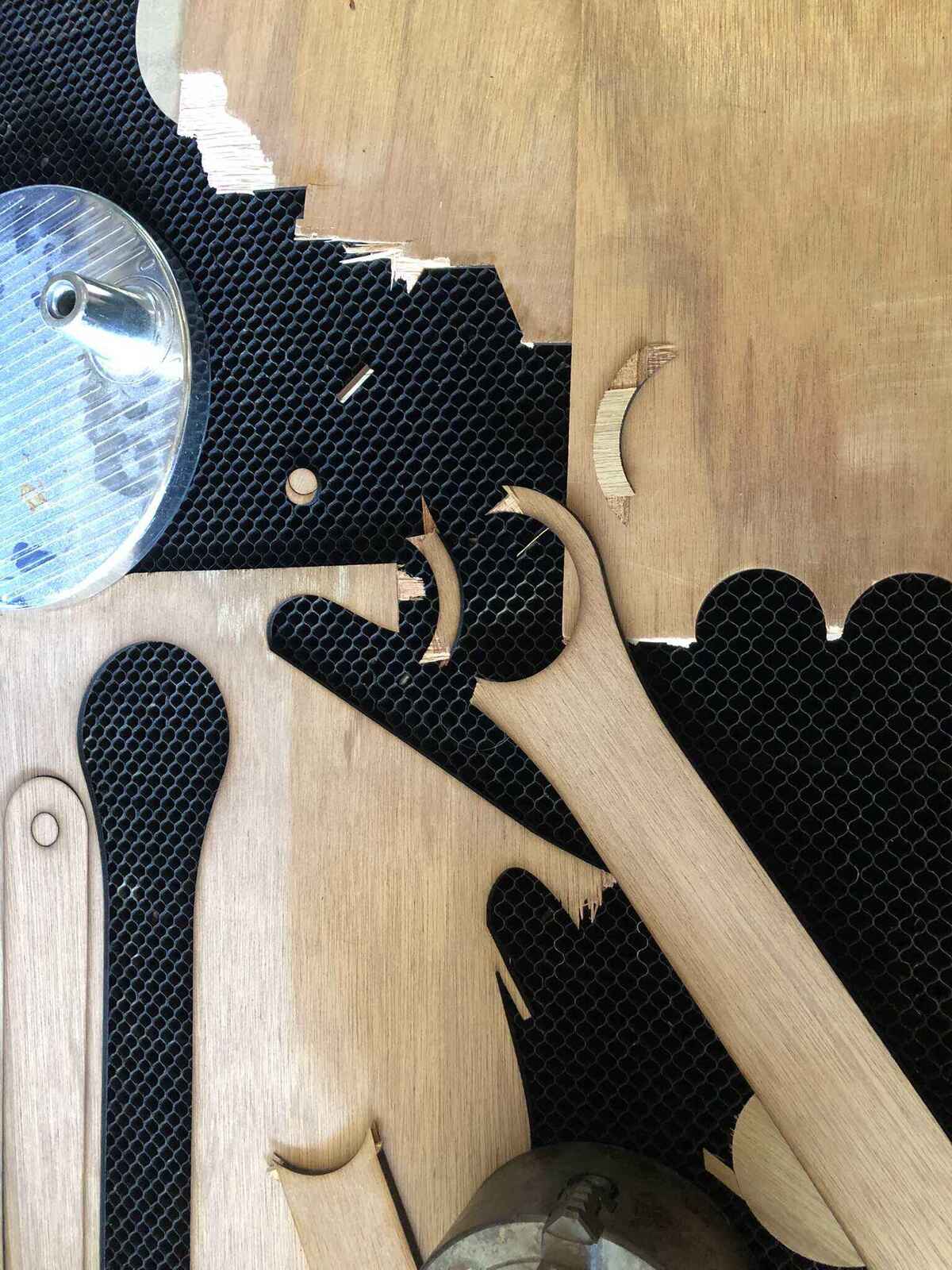
Cable management
On the big easle, I have space in the back to hide all of the wires and electronics under a simple cardboard cable cover that can be removed easily.
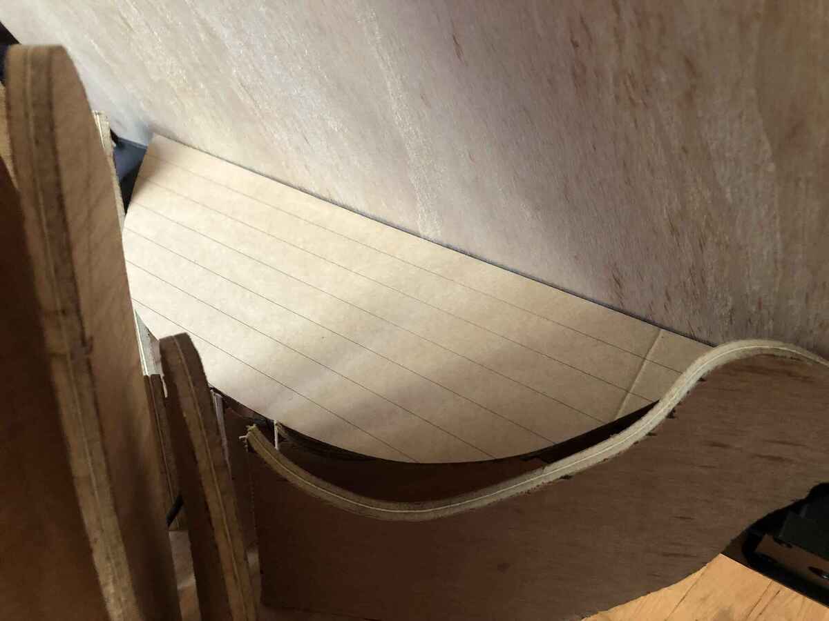
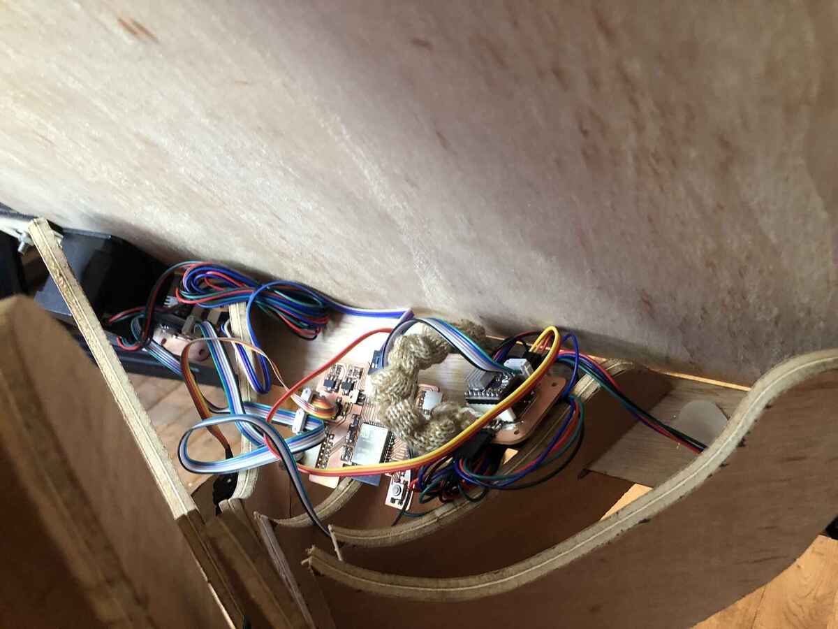
Since I couldn’t hide the servo cables under the linkage arms without it getting stuck in the gears (or it looking just bad in general), I decided the cables had to become part of the installation. I knitted a cable cover on a Dubied knitting machine at the HKU textile workshop. It’s knitted with a nice wool yarn. It’s a small circular tube to hide the servo motor cables.
On the small easle I made channels on the bottom of the frame for wiring, the PCB and a 9V battery. I hotglued the wires into the channels which hid them from view. I also hotglued the PCB in, but then I realized that powering the board externally didn’t work.
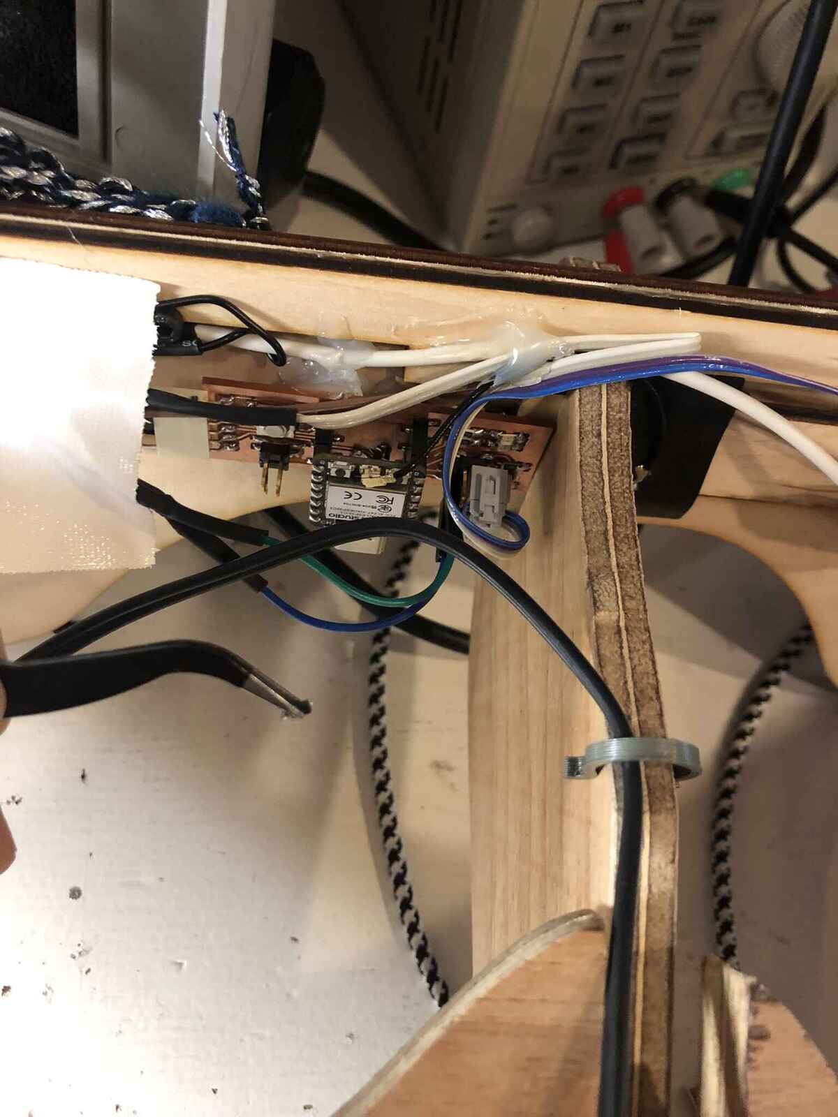
When troubleshooting the PCB (having the easle upside down in the electronics corner) I ripped off the traces leading to the 2x02 pins. I didn’t have time to make a new board, so I decided to power it via the onboard USB-C port instead. This meant that I had to move the board from its initial position, because the USB cable was poking out in the front. Since everything else was already positioned, cut and glued, I moved it down as well as I could so it wouldn’t be visible from the operating point of view.
Reflection
It’s been a ride. I’ve seen Fabacademy from the sideline for past two years and I’m very happy to have finally done it myself. It’s one thing to see others around you struggle and get deeper and deeper into all kinds of spirals, but a completely different thing to actually immerse yourself in it. I have learned a lot and I’m pretty proud of what I’ve managed to do in the past months.
I’ve heard Henk say that I could do it with ‘two fingers in your nose’ (a Dutch expression meaning you can do something without effort) countless of times, and as many times that that means that the bar is high. I have high expectations of myself so I liked the challenge, but the pressure was definitely on. I thrive within structured programs where you have to deliver frequently so I loved the rapid pace of the program. I can be a workaholic (and a ‘strebertje’, an overachiever) and try to give it my all for things that I love to do, so that’s what I did for the past 5 months. The rumors of the vanishing social life were true, and I was very happy that my partner didn’t move to the Netherlands yet, since it would have been a terrible time to live together with me.
For the first 3 months of Fabacademy I was using the weekly assignments to avoid starting with my final project. Instead, every time I started to think about my final project, I would come up with new ideas instead. I did that a couple of times until my final project research page was a 4000 word exploration and I had no plan. This problem is not new to me: I have a tendency to stay in the research and iteration phase forever and just start something new instead of finishing a project I already started. I was putting a little bit too much pressure on having the most amazing project ever, and I didn’t think my ideas were good enough until I ran out of time to worry about that in week 13. After that I had to stop using the weekly assignment as an excuse and get started.
In the beginning of Fabacademy I struggled with time management and making decisions in time. I wanted to do everything, but you are very much limited by time so at some point you become very good at weekly triage. Once I found my rhythm it was still a lot of work and I spent about 60 hours a week on it. It has been super fun and I’ve absolutely wished for it to be over. I’m going to miss it. I still can’t plan (or rather: follow a planning), but I do think I managed to combine my chaotic creative workflow with a more pragmatic Fabacademy spiral development pretty well in the end. I like making and experimenting and see where it takes me, but I also need to finish (half) a prototype before I can improve it, especially because I learn best by making.
I look forward to improving my machine (I already ordered some heavy motors) and make all kinds of new machines (after a nice summer holiday). I have many ideas that I had to stop myself from starting so I could focus on actually finishing the final project, so I think now it’s time to start something new! I think (hope) I will keep on using my Fabacademy blog to document future projects, also as an extension to my website which I conveniently used the same Jekyll template for. So: to be continued! And thanks Henk :-)
Files
PCB files; when using the SVGs in mods, set DPI to 72.
- KiCad files and SVGs for the ‘motherboard’ that I didn’t use in the end
- KiCad and SVG files for the output board (main board and stepper module)
- KiCad and SVG files for the input board
Design files:
Code
Input board
#include <BLEDevice.h>
#include <BLEUtils.h>
#include <BLEServer.h>

BLEServer *pServer;
BLEService *pService;
BLECharacteristic *pCharacteristic;

#define SERVICE_UUID        "d881bfae-0213-11ee-be56-0242ac120002"
#define CHARACTERISTIC_UUID "0b85454c-0214-11ee-be56-0242ac120002"


const int sensorPin1 = 2;
const int sensorPin2 = 3;

const int ledPin1 = 4;
const int ledPin2 = 5;

const int buttonPin = 8;
const int servoButtonPin = 9;

// Brush lifting with a button
int servoPos = 140;
int servoButtonPushCounter = 0;  // counter for the number of button presses
int servoButtonState = 0;        // current state of the button
int servoLastButtonState = 0;    // previous state of the button

int sensorValue1 = 0;   // the sensor value
int sensorMin1 = 4095;  // minimum sensor value
int sensorMax1 = 0;     // maximum sensor value

int sensorValue2 = 0;   // the sensor value
int sensorMin2 = 4095;  // minimum sensor value
int sensorMax2 = 0;     // maximum sensor value

int ledState1 = LOW;        // the current state of the output pin
int ledState2 = LOW;        // the current state of the output pin
int buttonState;            // the current reading from the input pin
int lastButtonState = LOW;  // the previous reading from the input pin

// the following variables are unsigned longs because the time, measured in
// milliseconds, will quickly become a bigger number than can be stored in an int.
unsigned long lastDebounceTime = 0;  // the last time the output pin was toggled
unsigned long debounceDelay = 50;    // the debounce time; increase if the output flickers


void setup() {
//  Serial.begin(115200);
//  while (!Serial) {
//    ; // wait for serial port to connect. Needed for native USB port only
//  }
  pinMode(ledPin1, OUTPUT);
  pinMode(ledPin2, OUTPUT);
  pinMode(sensorPin1, INPUT);
  pinMode(sensorPin2, INPUT);
  pinMode(buttonPin, INPUT_PULLUP);
  pinMode(servoButtonPin, INPUT_PULLUP);

  digitalWrite(ledPin1, ledState1);
  digitalWrite(ledPin2, ledState2);

//  Serial.println("Starting BLE work!");

  BLEDevice::init("XIAO input device board");

  // C++ code: in class BLEDevice we call createServer(); this method returns a pointer (=address)
  // of type BLEServer and we store that in a variable named pServer of type pointer to BLEServer
  // (BLEServer *).
  pServer = BLEDevice::createServer();

  pService = pServer->createService(SERVICE_UUID);
  pCharacteristic = pService->createCharacteristic(
                      CHARACTERISTIC_UUID,
                      BLECharacteristic::PROPERTY_READ |
                      BLECharacteristic::PROPERTY_WRITE
                    );

  pService->start();
  // BLEAdvertising *pAdvertising = pServer->getAdvertising();  // this still is working for backward compatibility
  BLEAdvertising *pAdvertising = BLEDevice::getAdvertising();
  pAdvertising->addServiceUUID(SERVICE_UUID);
  pAdvertising->setScanResponse(true);
  pAdvertising->setMinPreferred(0x06);  // functions that help with iPhone connections issue
  pAdvertising->setMinPreferred(0x12);
  BLEDevice::startAdvertising();
//  Serial.println("Characteristic defined");
}

void loop() {
  int reading = digitalRead(buttonPin);
  servoButtonState = digitalRead(servoButtonPin);
//  Serial.println(servoButtonState);

  // If the switch changed, due to noise or pressing:
  if (reading != lastButtonState) {
    // reset the debouncing timer
    lastDebounceTime = millis();
  }

  if ((millis() - lastDebounceTime) > debounceDelay) {

    // if the button state has changed:
    if (reading != buttonState) {
      buttonState = reading;

      // only toggle the LED if the new button state is HIGH
      if (buttonState == LOW) {
//        Serial.println("start");
        digitalWrite(ledPin1, HIGH);
        digitalWrite(ledPin2, HIGH);

        // determine min and max values of both sensors for 5 seconds
        for (int timems = 0; timems < 5000; timems++) {
          sensorValue1 = analogRead(sensorPin1);
          sensorValue2 = analogRead(sensorPin2);

          // record the maximum sensor value
          if (sensorValue1 > sensorMax1) {
            sensorMax1 = sensorValue1;
          }
          // record the maximum sensor value
          if (sensorValue2 > sensorMax2) {
            sensorMax2 = sensorValue2;
          }

          // record the minimum sensor value
          if (sensorValue1 < sensorMin1) {
            sensorMin1 = sensorValue1;
          }
          // record the minimum sensor value
          if (sensorValue2 < sensorMin2) {
            sensorMin2 = sensorValue2;
          }
          delay(1);
        }
        // signal the end of the calibration period
        digitalWrite(ledPin1, LOW);
        digitalWrite(ledPin2, LOW);

//        Serial.print("Results for sensor 1: ");
//
//        Serial.print(sensorMin1);
//        Serial.print("\t");
//        Serial.println(sensorMax1);
//
//        Serial.print("Results for sensor 2: ");
//
//        Serial.print(sensorMin2);
//        Serial.print("\t");
//        Serial.println(sensorMax2);
      }
    }

    sensorValue1 = analogRead(sensorPin1);
    sensorValue2 = analogRead(sensorPin2);

//    Serial.print(sensorValue1);
//    Serial.print("\t");
//    Serial.print(sensorValue2);
//    Serial.print("\t");

    sensorValue1 = constrain(sensorValue1, sensorMin1, sensorMax1);
    sensorValue1 = map(sensorValue1, sensorMin1, sensorMax1, 0, 300);
//    Serial.print("constrained and mapped:");
//    Serial.print("\t");
//    Serial.print(sensorValue1);
//    Serial.print("\t");

    sensorValue2 = constrain(sensorValue2, sensorMin2, sensorMax2);
    sensorValue2 = map(sensorValue2, sensorMin2, sensorMax2, 0, 300);

//    Serial.print(sensorValue2);
//    Serial.print("\t");

    // fade the LED using the calibrated value:
    analogWrite(ledPin1, sensorValue1);
    analogWrite(ledPin2, sensorValue2);


    // Filtering the values by dividing by 10 then multiplying by 10

//    Serial.print("filtered:");
//    Serial.print("\t");
    sensorValue1 = sensorValue1 / 5;
    sensorValue1 = sensorValue1 * 5;
//    Serial.print(sensorValue1);
//    Serial.print("\t");

    sensorValue2 = sensorValue2 / 5;
    sensorValue2 = sensorValue2 * 5;
//    Serial.println(sensorValue2);

    // compare the buttonState to its previous state
    if (servoButtonState != servoLastButtonState) {
      // if the state has changed, increment the counter
      if (servoButtonState == LOW) {
        // if the current state is HIGH then the button went from off to on:
        servoButtonPushCounter++;
//        Serial.println("on");
//        Serial.print("number of button pushes: ");
//        Serial.println(servoButtonPushCounter);
      } //else {
        // if the current state is LOW then the button went from on to off:
//        Serial.println("on to off");
  //    }
      // Delay a little bit to avoid bouncing
      delay(50);
    }
    // save the current state as the last state, for next time through the loop
    servoLastButtonState = servoButtonState;

    if (servoButtonPushCounter % 2 == 0) {
//      Serial.println("modulo 2 is 0");
      servoPos = 140;

    } else {
      servoPos = 0;
    }

    String valueString1 = String(sensorValue1);
    String valueString2 = String(sensorValue2);
    String valueString3 = String(servoPos);
    String bothValues = String(valueString1 + "," + valueString2 + "," + valueString3);

//    Serial.println(bothValues);
    pCharacteristic->setValue(bothValues.c_str()); // expects 0 terminated string, converts String to c_str which is a character array
    pCharacteristic->notify();
    delay(50);
  }

  // save the reading. Next time through the loop, it'll be the lastButtonState:
  lastButtonState = reading;
}
Output board
/**
   A BLE client example that is rich in capabilities.
   There is a lot new capabilities implemented.
   author unknown
   updated by chegewara
   Modified by Michelle Vossen
*/

#include "BLEDevice.h"
//#include "BLEScan.h"
#include <AccelStepper.h>
#include <UniversalTimer.h>
#include <ESP32Servo.h>

Servo myservo;  // create servo object to control a servo

int pos = 140;    // variable to store the servo position

// Define servo motor pin
const int servoPin = 32;

UniversalTimer timer(500, true);

// Define stepper pins

const int dirPin1 = 27;
const int stepPin1 = 26;
const int sleepResetPin1 = 25;

const int dirPin2 = 17;
const int stepPin2 = 2;
const int sleepResetPin2 = 15;

const int spd = 100;
const int acc = 100;

// Define motor interface type
#define motorInterfaceType 1 //AccelStepper::DRIVER

// Creates an instance
AccelStepper myStepper1(motorInterfaceType, stepPin1, dirPin1);
AccelStepper myStepper2(motorInterfaceType, stepPin2, dirPin2);
//AccelStepper myStepper3(motorInterfaceType, stepPin3, dirPin3);

// To convert the incoming string into ints
int i;
char delimiter[] = ",";
char *p;
char string[128];
String sensorValuesString[3];
int sensorValue1;
int sensorValue2;
String valueString;

BLERemoteService* pRemoteService;
BLEClient*  pClient;

// The remote service we wish to connect to.
static BLEUUID serviceUUID("d881bfae-0213-11ee-be56-0242ac120002");
// The characteristic of the remote service we are interested in.
static BLEUUID    charUUID("0b85454c-0214-11ee-be56-0242ac120002");

static boolean doConnect = false;
static boolean connected = false;
static boolean doScan = false;
static BLERemoteCharacteristic* pRemoteCharacteristic;
static BLEAdvertisedDevice* myDevice;

static void notifyCallback(
  BLERemoteCharacteristic* pBLERemoteCharacteristic,
  uint8_t* pData,
  size_t length,
  bool isNotify) {
  Serial.print("Notify callback for characteristic ");
  Serial.print(pBLERemoteCharacteristic->getUUID().toString().c_str());
  Serial.print(" of data length ");
  Serial.println(length);
  Serial.print("data: ");
  Serial.write(pData, length);
  Serial.println();
}

class MyClientCallback : public BLEClientCallbacks {
    void onConnect(BLEClient* pclient) {
    }

    void onDisconnect(BLEClient* pclient) {
      connected = false;
      Serial.println("onDisconnect");
    }
};

bool connectToServer() {
  Serial.print("Forming a connection to ");
  Serial.println(myDevice->getAddress().toString().c_str());

  pClient  = BLEDevice::createClient();
  Serial.println(" - Created client");

  pClient->setClientCallbacks(new MyClientCallback());

  // Connect to the remote BLE Server.
  pClient->connect(myDevice);  // if you pass BLEAdvertisedDevice instead of address, it will be recognized type of peer device address (public or private)
  Serial.println(" - Connected to server");
  pClient->setMTU(517); //set client to request maximum MTU from server (default is 23 otherwise)

  // Obtain a reference to the service we are after in the remote BLE server.
  pRemoteService = pClient->getService(serviceUUID);
  if (pRemoteService == nullptr) {
    Serial.print("Failed to find our service UUID: ");
    Serial.println(serviceUUID.toString().c_str());
    pClient->disconnect();
    return false;
  }
  Serial.println(" - Found our service");


  // Obtain a reference to the characteristic in the service of the remote BLE server.
  pRemoteCharacteristic = pRemoteService->getCharacteristic(charUUID);
  if (pRemoteCharacteristic == nullptr) {
    Serial.print("Failed to find our characteristic UUID: ");
    Serial.println(charUUID.toString().c_str());
    pClient->disconnect();
    return false;
  }
  Serial.println(" - Found our characteristic");

  // Read the value of the characteristic.
  if (pRemoteCharacteristic->canRead()) {
    std::string value = pRemoteCharacteristic->readValue();
    Serial.print("The characteristic value was: ");
    Serial.println(value.c_str());
  }

  if (pRemoteCharacteristic->canNotify())
    pRemoteCharacteristic->registerForNotify(notifyCallback);

  connected = true;
  return true;
}


/**
   Scan for BLE servers and find the first one that advertises the service we are looking for.
*/
class MyAdvertisedDeviceCallbacks: public BLEAdvertisedDeviceCallbacks {
    /**
        Called for each advertising BLE server.
    */
    void onResult(BLEAdvertisedDevice advertisedDevice) {
      Serial.print("BLE Advertised Device found: ");
      Serial.println(advertisedDevice.toString().c_str());

      // We have found a device, let us now see if it contains the service we are looking for.
      if (advertisedDevice.haveServiceUUID() && advertisedDevice.isAdvertisingService(serviceUUID)) {

        BLEDevice::getScan()->stop();
        myDevice = new BLEAdvertisedDevice(advertisedDevice);
        doConnect = true;
        doScan = true;

      } // Found our server
    } // onResult
}; // MyAdvertisedDeviceCallbacks

//--------------------------------------------------

void setup() {
  Serial.begin(115200);
  while (!Serial) {
    ; // wait for serial port to connect. Needed for native USB port only
  }
  Serial.println("Starting Arduino BLE Client application...");
  BLEDevice::init("");

  // Retrieve a Scanner and set the callback we want to use to be informed when we
  // have detected a new device.  Specify that we want active scanning and start the
  // scan to run for 5 seconds.
  BLEScan* pBLEScan = BLEDevice::getScan();
  pBLEScan->setAdvertisedDeviceCallbacks(new MyAdvertisedDeviceCallbacks());
  pBLEScan->setInterval(1349);
  pBLEScan->setWindow(449);
  pBLEScan->setActiveScan(true);
  pBLEScan->start(5, false);

  pinMode(sleepResetPin1, OUTPUT);
  pinMode(sleepResetPin2, OUTPUT);
  digitalWrite(sleepResetPin1, HIGH);
  digitalWrite(sleepResetPin2, HIGH);

  myStepper1.setMaxSpeed(spd);
  myStepper1.setAcceleration(acc);
  myStepper1.setSpeed(spd);
  myStepper1.moveTo(-100);          // - is CW, for right stepper
  myStepper1.setCurrentPosition(0);  // turn previous position into new 0 position
  myStepper1.setSpeed(spd);         // setCurrentPosition() has a side effect of setting the current motor speed to 0

  myStepper2.setMaxSpeed(spd);
  myStepper2.setAcceleration(acc);
  myStepper2.setSpeed(spd);
  myStepper2.moveTo(100); // + is CCW, for left stepper
  myStepper2.setCurrentPosition(0);  // turn previous position into new 0 position
  myStepper2.setSpeed(spd);         // setCurrentPosition() has a side effect of setting the current motor speed to 0

  timer.start();

  myservo.attach(servoPin, 400, 2500);
  myservo.write(pos);

} // End of setup.


// This is the Arduino main loop function.
void loop() {
  //      Serial.println(sensorValue1);
  //      Serial.println(sensorValue2);

//  if (myStepper1.distanceToGo() == 0)
  myStepper1.moveTo(-sensorValue1);

  // Move the motor one step
  myStepper1.run();

//  if (myStepper2.distanceToGo() == 0)
  myStepper2.moveTo(sensorValue2);

  // Move the motor one step
  myStepper2.run();


  if (timer.check()) {

    // If the flag "doConnect" is true then we have scanned for and found the desired
    //z BLE Server with which we wish to connect.  Now we connect to it.  Once we are
    // connected we set the connected flag to be true.
    if (doConnect == true) {
      if (connectToServer()) {
        Serial.println("We are now connected to the XIAO ESP BLE Server.");
      } else {
        Serial.println("We have failed to connect to the server; there is nothing more we will do.");
      }
      doConnect = false;
    }

    if (connected) {
      // Read the value of the characteristic.
      if (pRemoteCharacteristic->canRead()) {
        std::string value = pRemoteCharacteristic->readValue();
        Serial.print("The characteristic value was: ");
        Serial.println(value.c_str());

        // Convert received data to 3 separate integers
        char *cstr = &value[0];
        i = 0;
        p = strtok(cstr, delimiter);

        while (p && i < 3)
        {
          sensorValuesString[i] = p;
          p = strtok(NULL, delimiter);
          ++i;
        }

        sensorValue1 = sensorValuesString[0].toInt();
        sensorValue2 = sensorValuesString[1].toInt();
        pos = sensorValuesString[2].toInt();
        myservo.write(pos);

        return;
      }
    } else if (doScan) {
      BLEDevice::getScan()->start(0); // restart scanning if the connection is lost
      myservo.write(140);

      return;
    }
  }
}