- Assignments
- KiCad
- Milling
- Programming
- BLE
- BLE servo control
- Finally working
- Programming explanation by Pieter and Bas
- Group assignment
- Files
- Erwin’s lecture notes
- Lecture notes
Networking and Communications
This week I focused on PCB design for my final project and Bluetooth communication between two ESP32 boards: one WROOM and one XIAO board. I made a (failed) ‘motherboard’ for my final project: an ESP32 WROOM with 3 stepper motors and 2 servo motors to actuate the brush plotter wheels and brush. This is the board I want to control with Bluetooth.
Assignments
| Progress | Task |
|---|---|
| Done | Group assignment: send a message between two projects & document your work |
| Done | Documented your project and what you have learned from implementing networking and/or communication protocols. |
| Done | Explained the programming process(es) you used. |
| Done | Outlined problems and how you fixed them. |
| Done | Included design files (or linked to where they are located if you are using a board you have designed and fabricated earlier) and original code. |
| Done | Included a ‘hero shot’ of your network and/or communications setup |
KiCad
To make the ‘motherboard’ for my final project, I started out with the wiring of the board based on the example board for the ESP WROOM for this week (the board I used as reference during input devices as well) and on the hello.DRV8428-D11C.

First I wired only one of the 3 drivers, looking carefully how the driver was wired in the image above. After that I could copy and paste the driver wiring and change some of the names and connect the driver pins to other pins on the ESP.
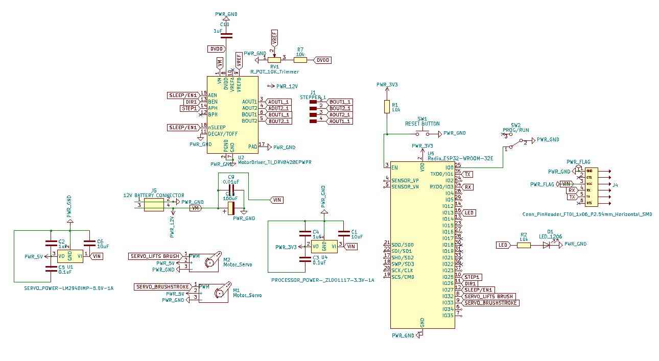
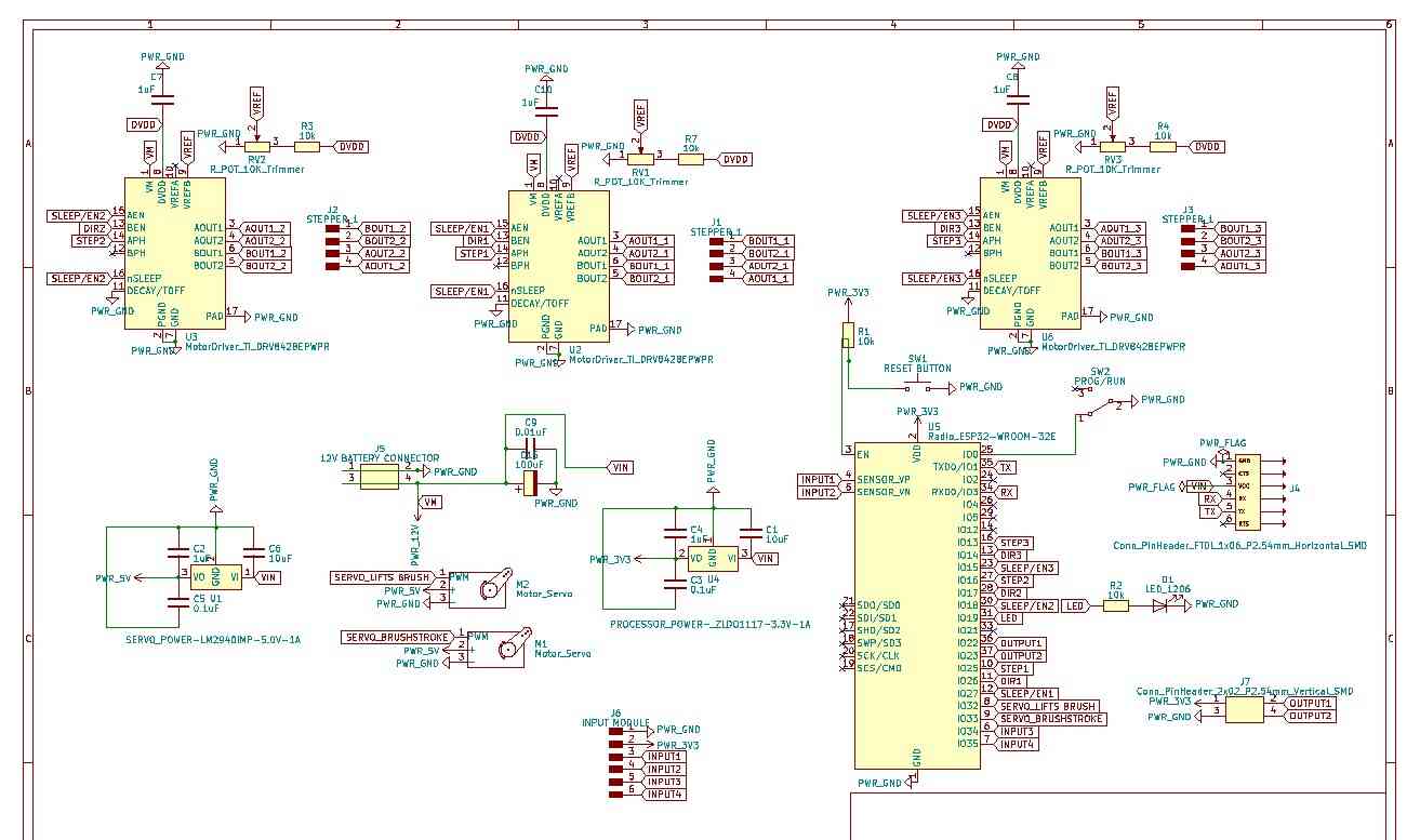
Then after adding the other two drivers this was the schematic:
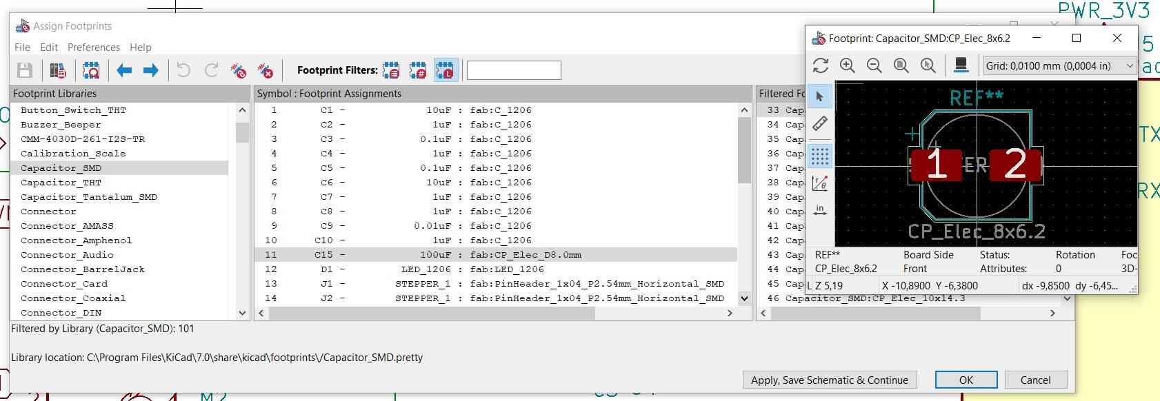
The big electrolytic capacitor didn’t have a footprint in the fab library so I linked a similar one.
Since I’m eternally confused by the schematic and footprint names, and the GPIO and physical pin numbering, I blocked the wrong pins in the image before so I fixed that.
Then it was time for the massive rat’s nest. In EESchema, I was wiring everything to the ESP while constantly checking the PCB editor to see where the actual pins were on the board (learning from the wiring disaster I had before during input devices week with the ESP WROOM). This made routing the tracks in the PCB editor way more pleasant, but it still took a couple of hours.
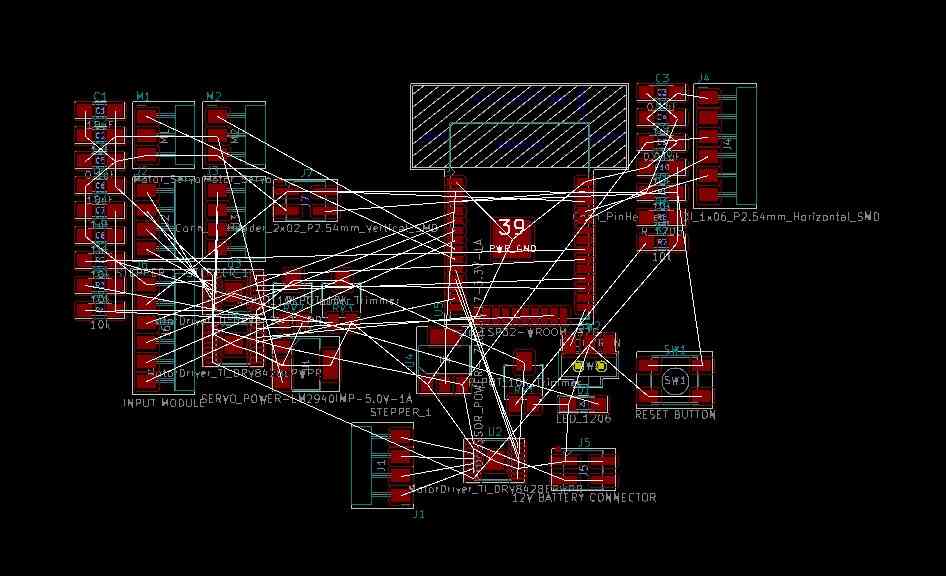
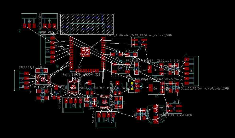
I had to fiddle with the design rules since the driver chip legs were so close to each other that there was no way to legally route anything to them with my default settings. I changed the clearance to the distance between the pins (0.2mm) when routing the driver pins, then changed it back to the regular 0.4mm for the rest of the traces. The design rules checker was pretty much rendered useless after this so I had to quadruple check everything.
![]()
![]()
I had to use a bunch of 0 Ohm jumpers to find my way out of the rat’s nest.

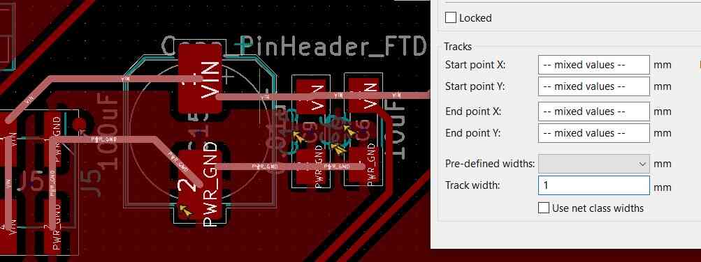
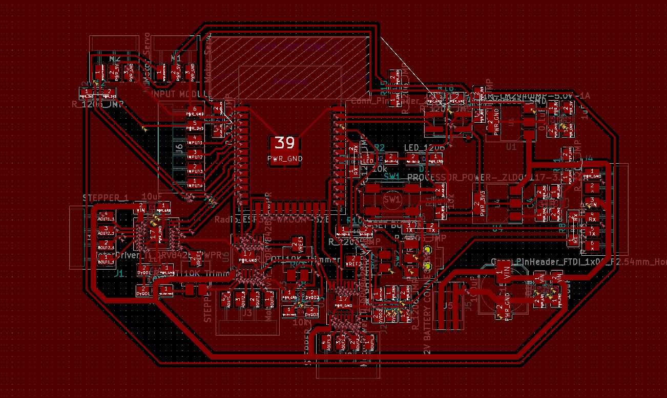
For the 12V power line I increased the track width to 1mm wherever I could.
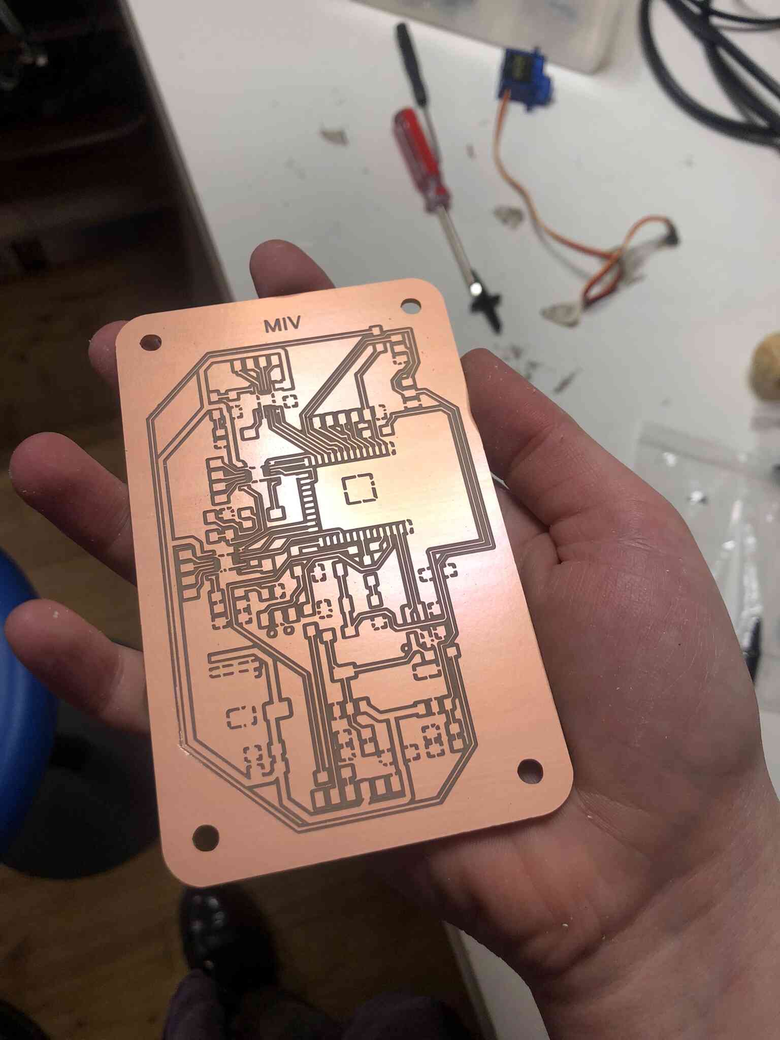
Final board with ground pour; I made the cut-out with drilling holes in Illustrator.
Milling & soldering
Milling the board on the Modela took about an hour. Look how beautiful she is:
I did some improvised reflow under the driver chip to connect it to ground and soldered the tiny legs successfully (if I can believe the multimeter).
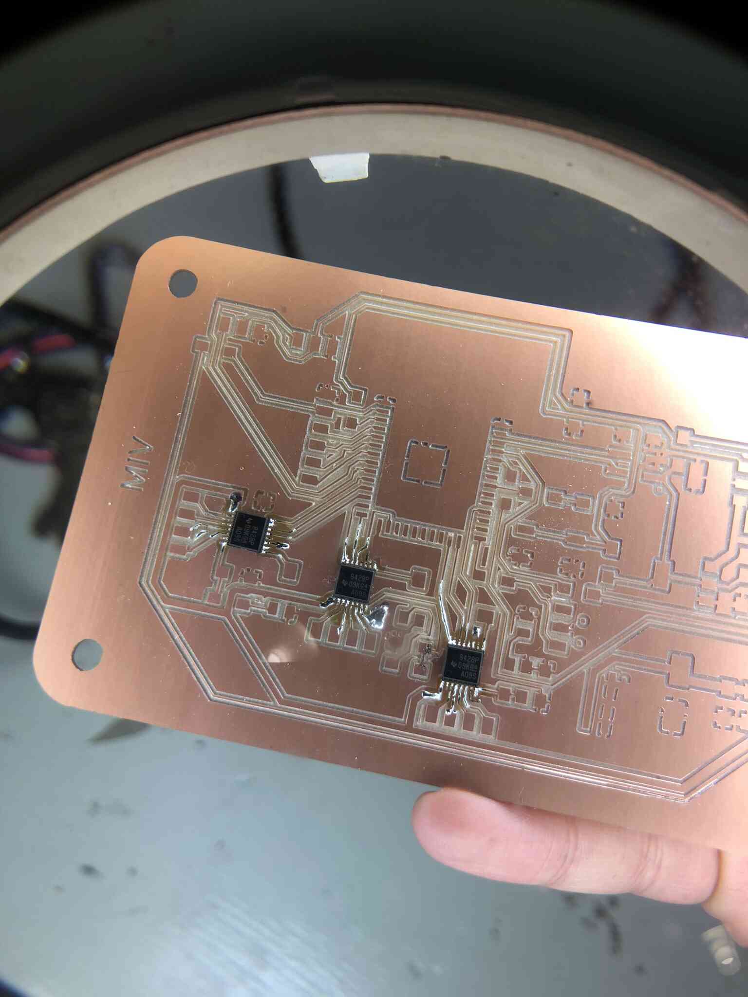
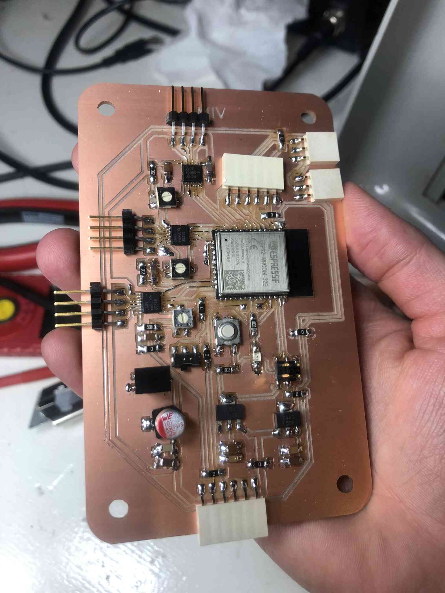
After a long time of soldering I was done (I forgot one 0 Ohm resistor that I added after this picture).
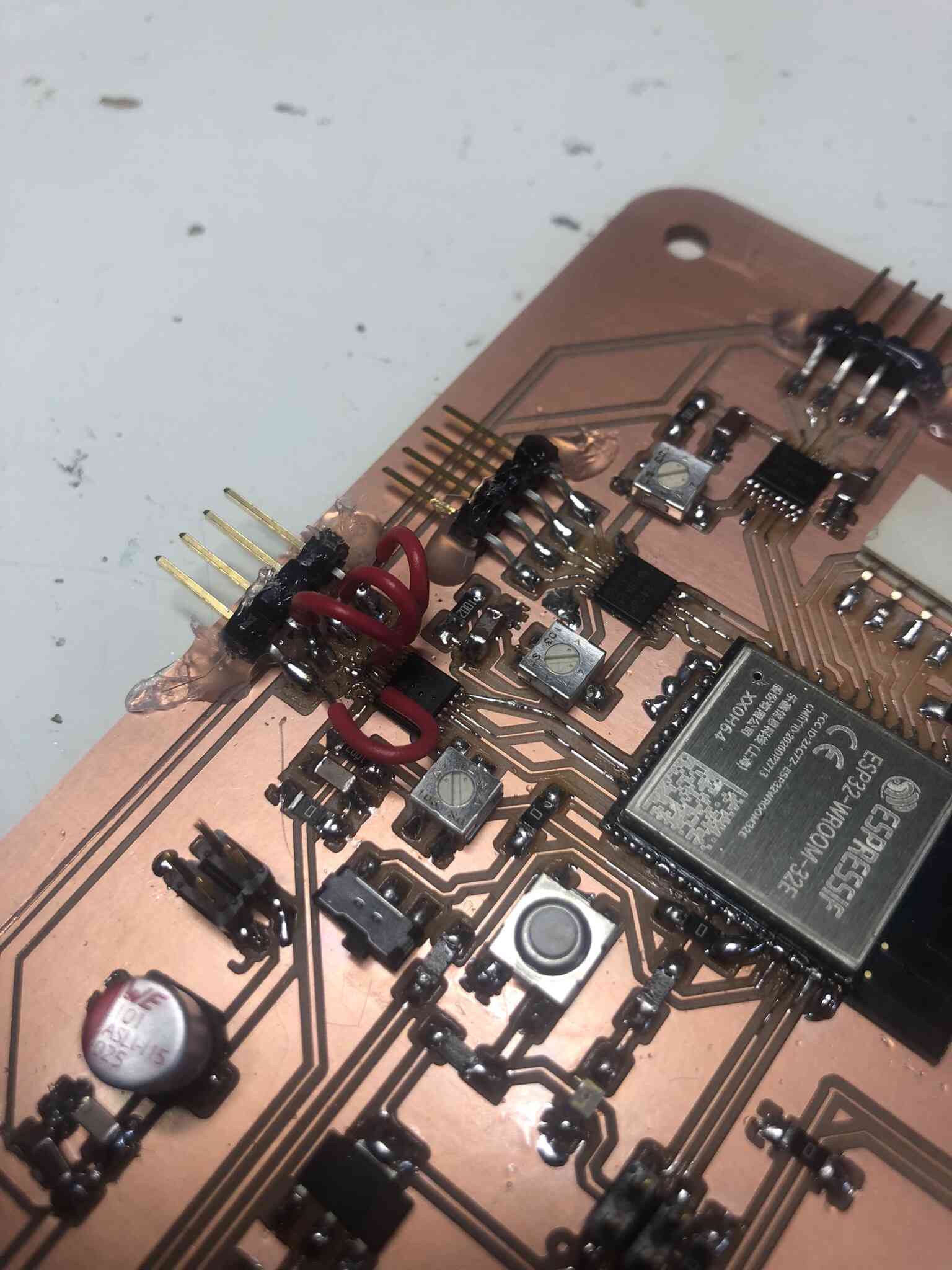
I ripped off the traces of one of the stepper motors so I tried very hard to make wire bridges, which somehow seemed to work when measuring everything.

Milling
I designed and made the board in one go, but I should’ve made it more as a modular board because if one thing goes wrong I probably have to redo the entire board. I also had to trick mods because the pins for the motor driver are too close together for the smallest milling bit that we have (0.4mm) so I put a diameter of 0.2mm but then it’s making the other traces way too small.
One solution could be to turn the track with to 0.6mm, so when you’re using a 0.4mm mill and using a 0.2mm setting in mods, the track would end up being 0.4mm instead of 0.2mm. However it’s smarter do that from the beginning, and it’s not watertight since it gives different issues when tracks are too close together. In any case I thought about that too late.
Programming
A fatal error occurred: Failed to connect to ESP32-C3: Invalid head of packet (0x00): Possible serial noise or corruption.
I was very worried until I realized that I forgot a zero ohm jumper on the RX line. After soldering it on however it still didn’t work and I got the same error. I measured and checked again and again but no luck.
Then I resoldered the RX and TX pins and I got this error:
esptool.py v4.5.1
Serial port COM34
Connecting....
Chip is ESP32-D0WD-V3 (revision v3.0)
Features: WiFi, BT, Dual Core, 240MHz, VRef calibration in efuse, Coding Scheme None
Crystal is 40MHz
MAC: 7c:9e:bd:cf:e8:18
Uploading stub...
Running stub...
Stub running...
Changing baud rate to 921600
Changed.
Configuring flash size...
Flash will be erased from 0x00001000 to 0x00005fff...
Flash will be erased from 0x00008000 to 0x00008fff...
Flash will be erased from 0x0000e000 to 0x0000ffff...
Flash will be erased from 0x00010000 to 0x00049fff...
Compressed 18960 bytes to 13073...
Writing at 0x00001000... (100 %)
Traceback (most recent call last):
  File "esptool\__init__.py", line 1032, in _main
  File "esptool\__init__.py", line 832, in main
  File "esptool\cmds.py", line 586, in write_flash
  File "esptool\loader.py", line 131, in inner
  File "esptool\loader.py", line 1030, in flash_defl_block
  File "esptool\loader.py", line 435, in check_command
  File "esptool\loader.py", line 404, in command
  File "esptool\loader.py", line 337, in read
StopIteration

A fatal error occurred: The chip stopped responding.
A fatal error occurred: The chip stopped responding.
I then uploaded once more and it succeeded! So the issue was a cold solder joint I think. I saw a beautiful blinking LED.
Servo
I tested a servo and a 12V power supply.
I first tried the basic servo sweep code but I got this error was when trying to use the Servo library which doesn’t work for esp. Downloading the ESP32Servo library fixed that issue and the servo worked fine.
C:\Program Files (x86)\Arduino\libraries\Servo\src/Servo.h:77:2: error: #error "This library only supports boards with an AVR, SAM, SAMD, NRF52 or STM32F4 processor."
 #error "This library only supports boards with an AVR, SAM, SAMD, NRF52 or STM32F4 processor."
  ^~~~~
Servo testing code:
#include <ESP32Servo.h>

Servo myservo;  // create servo object to control a servo
// 16 servo objects can be created on the ESP32

int pos = 0;    // variable to store the servo position
// Recommended PWM GPIO pins on the ESP32 include 2,4,12-19,21-23,25-27,32-33
// Possible PWM GPIO pins on the ESP32-S2: 0(used by on-board button),1-17,18(used by on-board LED),19-21,26,33-42
// Possible PWM GPIO pins on the ESP32-S3: 0(used by on-board button),1-21,35-45,47,48(used by on-board LED)
// Possible PWM GPIO pins on the ESP32-C3: 0(used by on-board button),1-7,8(used by on-board LED),9-10,18-21
int servoPin = 33;


void setup() {
	// Allow allocation of all timers
	ESP32PWM::allocateTimer(0);
	ESP32PWM::allocateTimer(1);
	ESP32PWM::allocateTimer(2);
	ESP32PWM::allocateTimer(3);
	myservo.setPeriodHertz(50);    // standard 50 hz servo
	myservo.attach(servoPin, 1000, 2000); // attaches the servo on pin 18 to the servo object
	// using default min/max of 1000us and 2000us
	// different servos may require different min/max settings
	// for an accurate 0 to 180 sweep
}

void loop() {

	for (pos = 0; pos <= 180; pos += 1) { // goes from 0 degrees to 180 degrees
		// in steps of 1 degree
		myservo.write(pos);    // tell servo to go to position in variable 'pos'
		delay(15);             // waits 15ms for the servo to reach the position
	}
	for (pos = 180; pos >= 0; pos -= 1) { // goes from 180 degrees to 0 degrees
		myservo.write(pos);    // tell servo to go to position in variable 'pos'
		delay(15);             // waits 15ms for the servo to reach the position
	}
}
https://www.esp32.com/viewtopic.php?t=7893
Stepper
Before trying out the stepper motor, I tried to power the board from a 12V adapter; the first one didn’t work even though I confirmed it did output 12V. I swapped the adapter with another one (higher amperage rating of 3A instead of 1A) and then it did power the board and the servo, and I measured 3.3V, 5V and 12V where they were supposed to be.
Now it was time to test the most important part of the board: the stepper and stepper drivers.
I’m using this stepper:
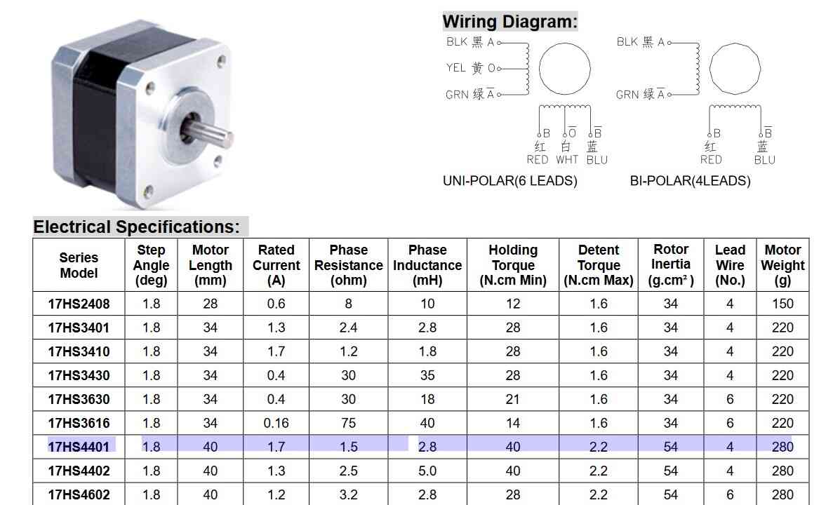
I modified Neil’s example code and uploaded it. It didn’t work, so I measured everything and went troubleshooting. I went to the datasheet to figure out if I missed anything.
DVDD & VREF
I read this in the datasheet:
Current set reference input. Maximum value 3 V. DVDD canbe used to provide VREF through a resistor divider.
I’m measuring 5V on DVDD1 and DVDD2 input, and only a few mV on the VREF lines and DVDD3, when the potentiometer is set to the full 10k Ohm. When lowering the resistance by turning the potentiometer, I measured that the voltage was going up. The maximum voltage on VREF is 3V, so I’m starting with about 2.2V.
Disaster
Then I was looking around some more and I came across this StackExchange post. This is when I realized I messed up.
There are 3 similar drivers :

    DRV8428 : Step/Dir interface
    DRV8428P: PWM
    DRV8428E: PH/EN
I realized I had the wrong datasheet in front of me; I have the DRV8428P that is controlled with PWM in a step/dir interface. Not the DRV8428E as I had in my schematic that is controlled with step/dir (which is also why the names of some of the pins were different but I ignored that because I was working from the pins that Neil connected in his board). The one Neil is using is the ‘regular’ 8428, so not the one that is in the fab library. I just assumed it was the same one we had and Neil was using. These are the 8428, 8428e and 8428p pin-outs respectively:
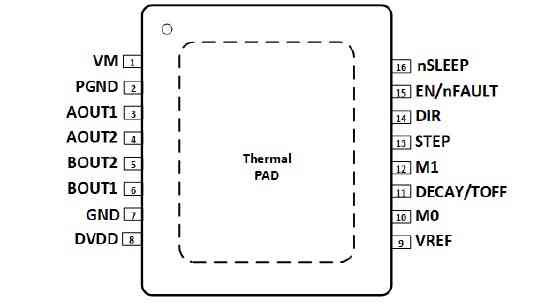
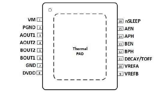
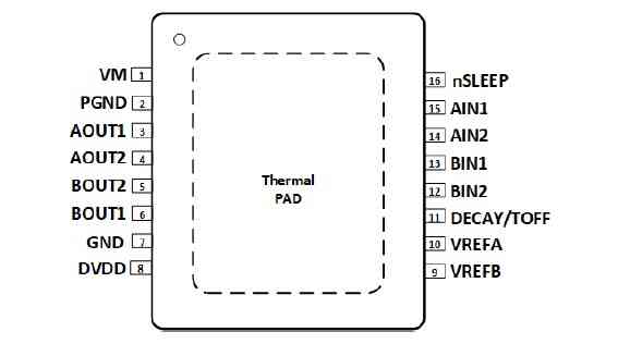
I started with a little bit of hope since the pins on the left side of the driver were the same on both chips. Sadly the right side crushed my hope and I think I can safely declare my beautiful board useless. I guess this is my lesson to make modular boards, and to quadruple-check if I’m actually using the same component, and to check if the component in the KiCad library is actually the right one. RIP the beautiful board that I spent many hours on.
Another mistake was that I didn’t mill away the material in the keep-out zone, because I didn’t know that keep-out meant actually no copper at all; I thought it was just an area where no wires could be. I don’t understand why it wasn’t part of the footprint.
For what it’s worth, the code that I tried to use with the wrong chip:
#define LEDA 19

#define EN 25
#define DIR 27
#define STEP 26

#define EN2 15
#define DIR2 17
#define STEP2 2

#define EN3 14
#define DIR3 13
#define STEP3 12

#define NSTEPS 1000
#define DELAYHIGH 10
#define DELAYLOW 1000
#define BLINK 100

void setup() {
  pinMode(LEDA, OUTPUT);
  digitalWrite(EN, HIGH);
  pinMode(EN, OUTPUT);
  digitalWrite(STEP, LOW);
  pinMode(STEP, OUTPUT);
  digitalWrite(DIR, LOW);
  pinMode(DIR, OUTPUT);

  digitalWrite(EN2, HIGH);
  pinMode(EN2, OUTPUT);
  digitalWrite(STEP2, LOW);
  pinMode(STEP2, OUTPUT);
  digitalWrite(DIR2, LOW);
  pinMode(DIR2, OUTPUT);

  digitalWrite(EN3, HIGH);
  pinMode(EN3, OUTPUT);
  digitalWrite(STEP3, LOW);
  pinMode(STEP3, OUTPUT);
  digitalWrite(DIR3, LOW);
  pinMode(DIR3, OUTPUT);

}

void blink_off() {
  digitalWrite(LEDA, LOW);
  delay(BLINK);
  digitalWrite(LEDA, HIGH);
}

void do_steps() {
  digitalWrite(DIR, HIGH);
  for (int i = 0; i < NSTEPS; ++i) {
    digitalWrite(STEP, HIGH);
    delayMicroseconds(DELAYHIGH);
    digitalWrite(STEP, LOW);
    delayMicroseconds(DELAYLOW);
  }
  digitalWrite(DIR, LOW);
  for (int i = 0; i < NSTEPS; ++i) {
    digitalWrite(STEP, HIGH);
    delayMicroseconds(DELAYHIGH);
    digitalWrite(STEP, LOW);
    delayMicroseconds(DELAYLOW);
  }

  digitalWrite(DIR2, HIGH);
  for (int i = 0; i < NSTEPS; ++i) {
    digitalWrite(STEP2, HIGH);
    delayMicroseconds(DELAYHIGH);
    digitalWrite(STEP2, LOW);
    delayMicroseconds(DELAYLOW);
  }
  digitalWrite(DIR2, LOW);
  for (int i = 0; i < NSTEPS; ++i) {
    digitalWrite(STEP2, HIGH);
    delayMicroseconds(DELAYHIGH);
    digitalWrite(STEP2, LOW);
    delayMicroseconds(DELAYLOW);
  }

  digitalWrite(DIR3, HIGH);
  for (int i = 0; i < NSTEPS; ++i) {
    digitalWrite(STEP3, HIGH);
    delayMicroseconds(DELAYHIGH);
    digitalWrite(STEP3, LOW);
    delayMicroseconds(DELAYLOW);
  }
  digitalWrite(DIR3, LOW);
  for (int i = 0; i < NSTEPS; ++i) {
    digitalWrite(STEP3, HIGH);
    delayMicroseconds(DELAYHIGH);
    digitalWrite(STEP3, LOW);
    delayMicroseconds(DELAYLOW);
  }
}

void loop() {
  blink_off();
  do_steps();
}
Now I have to decide if I want to try again but wired correctly this time, or to move on to the A4988 module. It has way more documentation and a higher success rate. If I want to continue with the 8428P, this is the reference board and documentation to work from.


Time-wise it might be smartest to go for the A4988 with this tutorial & this one as a reference.
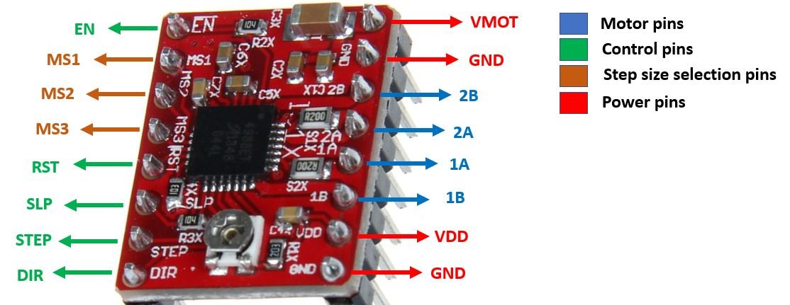
RST is a floating pin. If you’re not using this pin, connect it to an adjacent SLP/SLEEP pin to make it high and enable the driver. After the wake-up event (logic HIGH on the SLEEP pin), wait 1 millisecond before issuing a Step command to allow the charge pump to stabilize.
BLE
For now I’m working with the XIAO ESP32 and with the ESP WROOM board I made during input devices week. a I want to try out bluetooth communication between two ESP32 boards, because I am going to need it for my final project. I want a XIAO ESP32 to be the sender and an ESP32 WROOM to be the receiver. I’m following this tutorial.
Server
The steps to create a BLE server are defined like this:
- Create a BLE Server. In this case, the ESP32 acts as a BLE server.
- Create a BLE Service.
- Create a BLE Characteristic on the Service.
- Create a BLE Descriptor on the Characteristic.
- Start the Service.
- Start advertising, so it can be found by other devices.
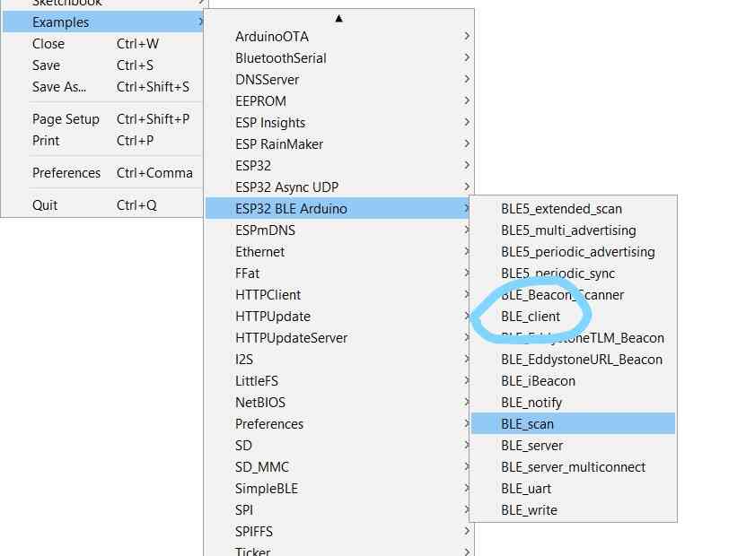
With the ESP32 board installed in the Arduino IDE comes the ESP32 BLE Arduino library with example codes. I started by uploading a slightly modified example code BLE_server to the XIAO ESP. This is the code:
/*
    Based on Neil Kolban example for IDF: https://github.com/nkolban/esp32-snippets/blob/master/cpp_utils/tests/BLE%20Tests/SampleServer.cpp
    Ported to Arduino ESP32 by Evandro Copercini
    updates by chegewara
    Modified by Michelle Vossen
*/

#include <BLEDevice.h>
#include <BLEUtils.h>
#include <BLEServer.h>

// See the following for generating UUIDs:
// https://www.uuidgenerator.net/

#define SERVICE_UUID        "4fafc201-1fb5-459e-8fcc-c5c9c331914b" // can stay the same
#define CHARACTERISTIC_UUID "beb5483e-36e1-4688-b7f5-ea07361b26a8" // can stay the same

void setup() {
  Serial.begin(115200);
  while (! Serial);
  Serial.println("Starting BLE work!");

  BLEDevice::init("XIAO ESP Server");
  BLEServer *pServer = BLEDevice::createServer();
  BLEService *pService = pServer->createService(SERVICE_UUID);
  BLECharacteristic *pCharacteristic = pService->createCharacteristic(
                                         CHARACTERISTIC_UUID,
                                         BLECharacteristic::PROPERTY_READ |
                                         BLECharacteristic::PROPERTY_WRITE
                                       );

  pCharacteristic->setValue("This is a message from the XIAO ESP Server to the ESP WROOM!");
  pService->start();
  // BLEAdvertising *pAdvertising = pServer->getAdvertising();  // this still is working for backward compatibility
  BLEAdvertising *pAdvertising = BLEDevice::getAdvertising();
  pAdvertising->addServiceUUID(SERVICE_UUID);
  pAdvertising->setScanResponse(true);
  pAdvertising->setMinPreferred(0x06);  // functions that help with iPhone connections issue
  pAdvertising->setMinPreferred(0x12);
  BLEDevice::startAdvertising(); // so it can be found by other devices
  Serial.println("Test test can you read this?");
}

void loop() {
  delay(2000);
}
This line is the line that I have to change to my sensor reading to send to the servo motors to manipulate the brush stroke later:
pCharacteristic->setValue("value");
Client
For the client side, I started with the example code in the same library called BLE_client which I modified slightly and uploaded to the ESP WROOM.
UUID
The remote service and characteristic UUID have to be the same as in the server code, otherwise they can’t find each other. UUID stands for Universally Unique Identifier, and it’s a unique name you have to give your devices so they can be found. A Universally Unique ID (UUID) is a 16 or 128-bit value used to identify the type of every attribute. The value of the attribute can be anything from strings to states to integers.
A UUID can identify a particular service provided by a Bluetooth device. There are shortened UUIDs for all types, services, and profiles specified in the SIG (Bluetooth Special Interest Group) that can be found here. You can also define your own UUID. You can generate one here.
I used the same ones as in the example code.
// The remote service we wish to connect to.
static BLEUUID serviceUUID("4fafc201-1fb5-459e-8fcc-c5c9c331914b");
// The characteristic of the remote service we are interested in.
static BLEUUID    charUUID("beb5483e-36e1-4688-b7f5-ea07361b26a8");
After the Characteristic Value Declaration follows either:
- a new Characteristic Declaration (there can be many characteristics grouped in a service).
- a new Service Declaration (there can be many services in a table).
- a Descriptor Declaration.

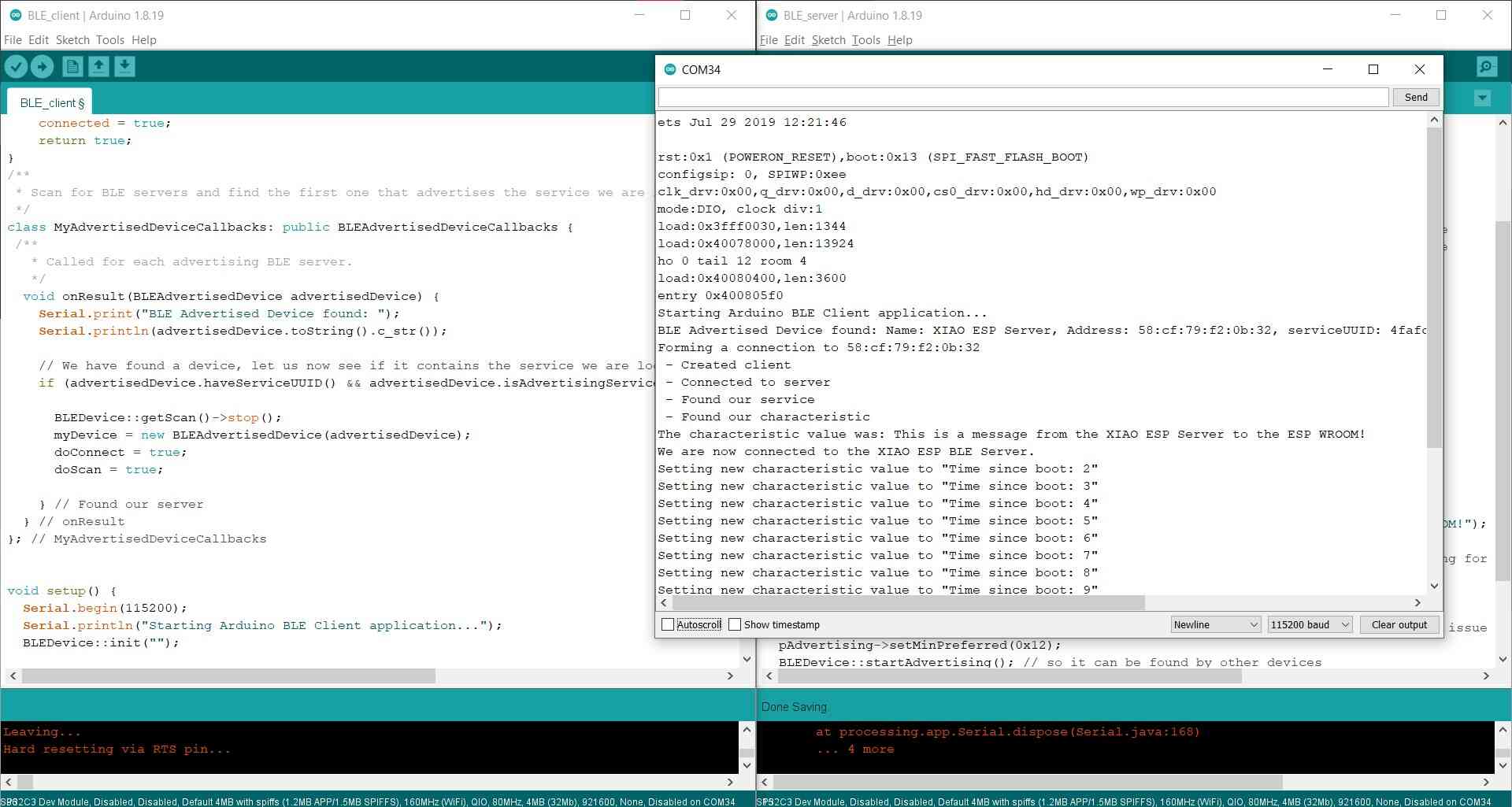
I uploaded the code and then opened the serial monitor on the client side. It worked pretty much straight out of the box, so that’s great:
Code used:
/**
 * A BLE client example that is rich in capabilities.
 * There is a lot new capabilities implemented.
 * author unknown
 * updated by chegewara
 * Modified by Michelle Vossen
 */

#include "BLEDevice.h"
//#include "BLEScan.h"

// The remote service we wish to connect to.
static BLEUUID serviceUUID("4fafc201-1fb5-459e-8fcc-c5c9c331914b");
// The characteristic of the remote service we are interested in.
static BLEUUID    charUUID("beb5483e-36e1-4688-b7f5-ea07361b26a8");

static boolean doConnect = false;
static boolean connected = false;
static boolean doScan = false;
static BLERemoteCharacteristic* pRemoteCharacteristic;
static BLEAdvertisedDevice* myDevice;

static void notifyCallback(
  BLERemoteCharacteristic* pBLERemoteCharacteristic,
  uint8_t* pData,
  size_t length,
  bool isNotify) {
    Serial.print("Notify callback for characteristic ");
    Serial.print(pBLERemoteCharacteristic->getUUID().toString().c_str());
    Serial.print(" of data length ");
    Serial.println(length);
    Serial.print("data: ");
    Serial.write(pData, length);
    Serial.println();
}

class MyClientCallback : public BLEClientCallbacks {
  void onConnect(BLEClient* pclient) {
  }

  void onDisconnect(BLEClient* pclient) {
    connected = false;
    Serial.println("onDisconnect");
  }
};

bool connectToServer() {
    Serial.print("Forming a connection to ");
    Serial.println(myDevice->getAddress().toString().c_str());

    BLEClient*  pClient  = BLEDevice::createClient();
    Serial.println(" - Created client");

    pClient->setClientCallbacks(new MyClientCallback());

    // Connect to the remove BLE Server.
    pClient->connect(myDevice);  // if you pass BLEAdvertisedDevice instead of address, it will be recognized type of peer device address (public or private)
    Serial.println(" - Connected to server");
    pClient->setMTU(517); //set client to request maximum MTU from server (default is 23 otherwise)

    // Obtain a reference to the service we are after in the remote BLE server.
    BLERemoteService* pRemoteService = pClient->getService(serviceUUID);
    if (pRemoteService == nullptr) {
      Serial.print("Failed to find our service UUID: ");
      Serial.println(serviceUUID.toString().c_str());
      pClient->disconnect();
      return false;
    }
    Serial.println(" - Found our service");


    // Obtain a reference to the characteristic in the service of the remote BLE server.
    pRemoteCharacteristic = pRemoteService->getCharacteristic(charUUID);
    if (pRemoteCharacteristic == nullptr) {
      Serial.print("Failed to find our characteristic UUID: ");
      Serial.println(charUUID.toString().c_str());
      pClient->disconnect();
      return false;
    }
    Serial.println(" - Found our characteristic");

    // Read the value of the characteristic.
    if(pRemoteCharacteristic->canRead()) {
      std::string value = pRemoteCharacteristic->readValue();
      Serial.print("The characteristic value was: ");
      Serial.println(value.c_str());
    }

    if(pRemoteCharacteristic->canNotify())
      pRemoteCharacteristic->registerForNotify(notifyCallback);

    connected = true;
    return true;
}
/**
 * Scan for BLE servers and find the first one that advertises the service we are looking for.
 */
class MyAdvertisedDeviceCallbacks: public BLEAdvertisedDeviceCallbacks {
 /**
   * Called for each advertising BLE server.
   */
  void onResult(BLEAdvertisedDevice advertisedDevice) {
    Serial.print("BLE Advertised Device found: ");
    Serial.println(advertisedDevice.toString().c_str());

    // We have found a device, let us now see if it contains the service we are looking for.
    if (advertisedDevice.haveServiceUUID() && advertisedDevice.isAdvertisingService(serviceUUID)) {

      BLEDevice::getScan()->stop();
      myDevice = new BLEAdvertisedDevice(advertisedDevice);
      doConnect = true;
      doScan = true;

    } // Found our server
  } // onResult
}; // MyAdvertisedDeviceCallbacks


void setup() {
  Serial.begin(115200);
  Serial.println("Starting Arduino BLE Client application...");
  BLEDevice::init("");

  // Retrieve a Scanner and set the callback we want to use to be informed when we
  // have detected a new device.  Specify that we want active scanning and start the
  // scan to run for 5 seconds.
  BLEScan* pBLEScan = BLEDevice::getScan();
  pBLEScan->setAdvertisedDeviceCallbacks(new MyAdvertisedDeviceCallbacks());
  pBLEScan->setInterval(1349);
  pBLEScan->setWindow(449);
  pBLEScan->setActiveScan(true);
  pBLEScan->start(5, false);
} // End of setup.


// This is the Arduino main loop function.
void loop() {

  // If the flag "doConnect" is true then we have scanned for and found the desired
  // BLE Server with which we wish to connect.  Now we connect to it.  Once we are
  // connected we set the connected flag to be true.
  if (doConnect == true) {
    if (connectToServer()) {
      Serial.println("We are now connected to the XIAO ESP BLE Server.");
    } else {
      Serial.println("We have failed to connect to the server; there is nothing more we will do.");
    }
    doConnect = false;
  }

  // If we are connected to a peer BLE Server, update the characteristic each time we are reached
  // with the current time since boot.
  if (connected) {
    String newValue = "Time since boot: " + String(millis()/1000);
    Serial.println("Setting new characteristic value to \"" + newValue + "\"");

    // Set the characteristic's value to be the array of bytes that is actually a string.
    pRemoteCharacteristic->writeValue(newValue.c_str(), newValue.length());
  }else if(doScan){
    BLEDevice::getScan()->start(0);
  }

  delay(1000); // Delay a second between loops.
} // End of loop
BLE servo control
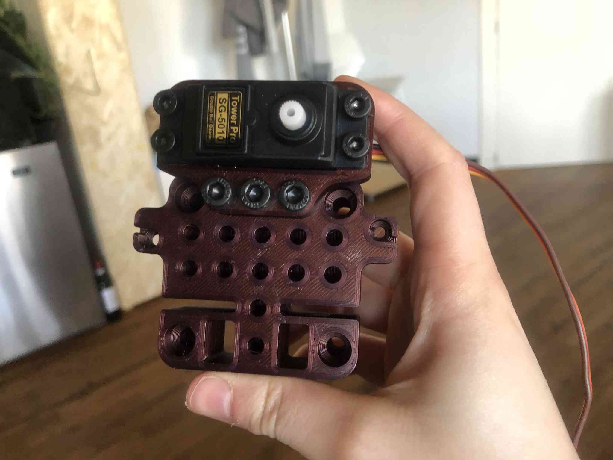
Now I wanted to move a servo on the client side depending on values sent by the server. I made this servo holder and pen holder to mount onto the Urumbu carriage that I printed to work on my final project prototype. I want to control 2 servo’s in the end but for now if I can control one over Bluetooth I’m happy.


I spent over 2 hours trying to figure out the PWM settings min and max for the servo. With this testing code I found 544 to 2382 (myservo.attach(servoPin, 544, 2382);) to work well, but then in my sweep code it was just doing random stuff and not working at all.

It’s super upsetting and frustrating that the datasheet doesn’t provide any insight into how to set it up. None of the sweep settings I used made any sense with what was happening to the servo. After that time it still wasn’t working. This was the best motion I got which is not 180 degrees at all.
After these two hours I plugged it into the XIAO ESP and it worked straight away which pissed me off immensely, but at least I could continue. I don’t know why it wasn’t working with the WROOM other than messy wiring on this specific board. I tried it out the next day with the big board I made this week, and it worked immediately too so it’s not like the servo doesn’t work with the WROOM.
Sensor data over Bluetooth
I wanted to use my heart shaped e-textiles circuit to gather the sensor data, but it didn’t want to work and the serial monitor didn’t want to print anything, not even a simple hello world. This really is not my my week. I spent over an hour again to troubleshoot my code to then not even have a working serial monitor with the XIAO ESP32 is pretty annoying. At some point I could see it connect and disconnect over and over again which wasn’t good either ()
In the end I found the solution on Reddit.
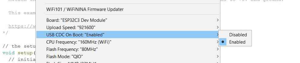
This drove me crazy. The XIAO ESP32C3 setting in the boards menu has the setting referenced here. It’s for enabling the USB serial vs the Serial1 on D6 and D7. It’s on the tools menu as “USB CDC on Boot: enabled”.
Setting USB CDC on Boot to enabled opened the serial monitor finally.
Then my code finally worked, but then the LED stopped working on the board (also with a simple Blink example).
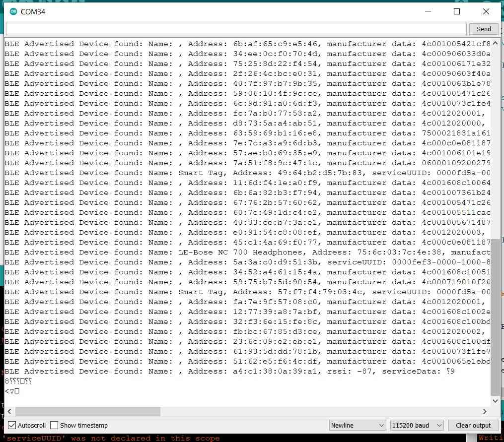
What also often happens is that the client can find many Bluetooth devices, but not the XIAO that’s right next to it. It seems more a matter of clicking the button at the right time and getting lucky than something logical. It seemed to have to do with this line and after commenting it out it worked again.
  while (!Serial) {
    ; // wait for serial port to connect. Needed for native USB port only
  }
Then to communicate the sensor data value, I needed to change something on the pCharacteristic->setValue(...); line but no matter what I tried, I kept getting different errors. I don’t understand what syntax it needs and all I can find are unanswered Stack Overflow answers.
C:\Users\mvoss\AppData\Local\Temp\arduino_modified_sketch_938441\BLE_server.ino: In function 'void setup()':
BLE_server:43:43: error: expected primary-expression before 'int'
   pCharacteristic->setValue(&sensorValue, int);
                                           ^~~
Multiple libraries were found for "BLEDevice.h"
 Used: C:\Users\mvoss\AppData\Local\Arduino15\packages\esp32\hardware\esp32\2.0.8\libraries\BLE
 Not used: C:\Users\mvoss\Documents\Arduino\libraries\Seeed_Arduino_rpcBLE
Using library BLE at version 2.0.0 in folder: C:\Users\mvoss\AppData\Local\Arduino15\packages\esp32\hardware\esp32\2.0.8\libraries\BLE
exit status 1
expected primary-expression before 'int'
I tried to move some stuff around so I could use setValue in the loop instead of the setup and it did upload though using the code below. However then I got all of these errors in the serial monitor.
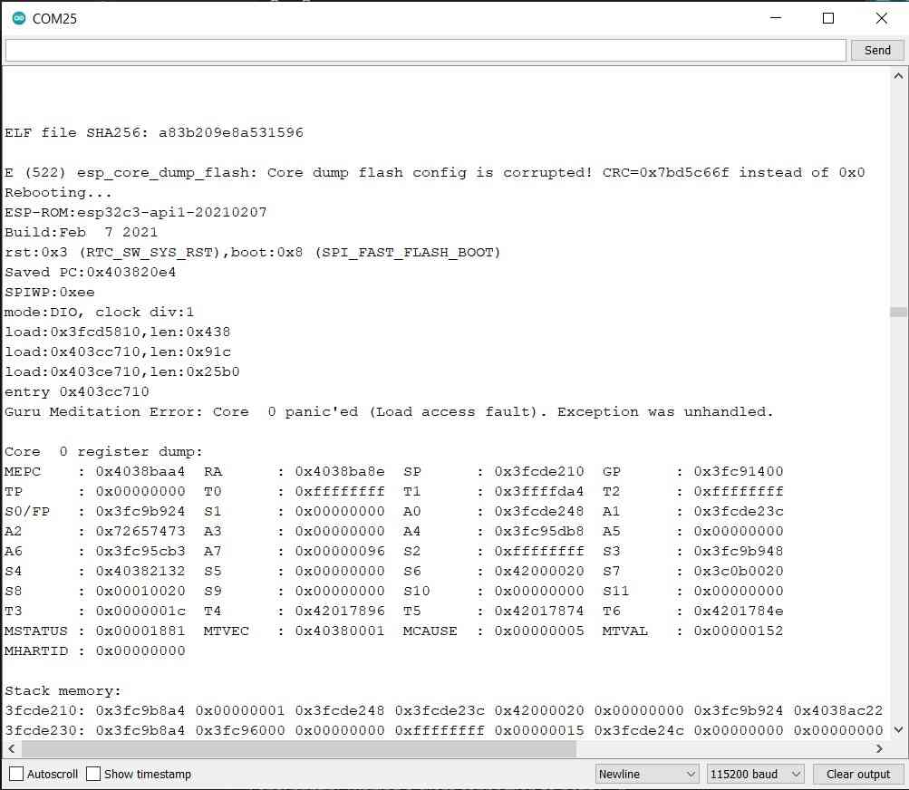
/*
    Based on Neil Kolban example for IDF: https://github.com/nkolban/esp32-snippets/blob/master/cpp_utils/tests/BLE%20Tests/SampleServer.cpp
    Ported to Arduino ESP32 by Evandro Copercini
    updates by chegewara
*/

#include <BLEDevice.h>
#include <BLEUtils.h>
#include <BLEServer.h>

const int sensorPin = 2;  // pin that the sensor is attached to
const int ledPin = 3;      // pin that the LED is attached to

int sensorValue = 0;   // the sensor value
int sensorMin = 1023;  // minimum sensor value
int sensorMax = 0;     // maximum sensor value

// See the following for generating UUIDs:
// https://www.uuidgenerator.net/

#define SERVICE_UUID        "4fafc201-1fb5-459e-8fcc-c5c9c331914b"
#define CHARACTERISTIC_UUID "beb5483e-36e1-4688-b7f5-ea07361b26a8"


BLEServer *pServer = BLEDevice::createServer();
BLEService *pService = pServer->createService(SERVICE_UUID);
BLECharacteristic *pCharacteristic = pService->createCharacteristic(
                                       CHARACTERISTIC_UUID,
                                       BLECharacteristic::PROPERTY_READ |
                                       BLECharacteristic::PROPERTY_WRITE

                                     );
void setup() {
  Serial.begin(115200);
  //  while (!Serial) {
  //    ; // wait for serial port to connect. Needed for native USB port only
  //  }
  pinMode(ledPin, OUTPUT);
  pinMode(sensorPin, INPUT);
  Serial.println("Starting BLE work!");

  BLEDevice::init("Long name works now");


  pCharacteristic->setValue("Set value on XIAO");

  pService->start();
  // BLEAdvertising *pAdvertising = pServer->getAdvertising();  // this still is working for backward compatibility
  BLEAdvertising *pAdvertising = BLEDevice::getAdvertising();
  pAdvertising->addServiceUUID(SERVICE_UUID);
  pAdvertising->setScanResponse(true);
  pAdvertising->setMinPreferred(0x06);  // functions that help with iPhone connections issue
  pAdvertising->setMinPreferred(0x12);
  BLEDevice::startAdvertising();
  Serial.println("Characteristic defined");
}

void loop() {
  Serial.println("start");
  digitalWrite(ledPin, HIGH);

  for (int timems = 0; timems < 5000; timems++) {
    sensorValue = analogRead(sensorPin);

    // record the maximum sensor value
    if (sensorValue > sensorMax) {
      sensorMax = sensorValue;
    }

    // record the minimum sensor value
    if (sensorValue < sensorMin) {
      sensorMin = sensorValue;
    }
    delay(1);
  }
  // signal the end of the calibration period
  digitalWrite(ledPin, LOW);
  Serial.print("Results: ");

  Serial.print(sensorMin);
  Serial.print("\t");
  Serial.println(sensorMax);
  for (int i = 0; i < 10000; i++) { // output

    sensorValue = analogRead(sensorPin);
    //    Serial.println(sensorValue);
    // in case the sensor value is outside the range seen during calibration
    sensorValue = constrain(sensorValue, sensorMin, sensorMax);

    // apply the calibration to the sensor reading
    sensorValue = map(sensorValue, sensorMin, sensorMax, 0, 255);
    pCharacteristic->setValue(sensorValue);
    pCharacteristic->write();


    // fade the LED using the calibrated value:
    analogWrite(ledPin, sensorValue);
    delay(1);
  }

  // Blink LED 3 times to indicate end of output cycle
  digitalWrite(ledPin, HIGH);
  delay(500);
  digitalWrite(ledPin, LOW);
  delay(500);
  digitalWrite(ledPin, HIGH);
  delay(500);
  digitalWrite(ledPin, LOW);
  delay(500);
  digitalWrite(ledPin, HIGH);
  delay(500);
  digitalWrite(ledPin, LOW);
  delay(500);
}
Finally working
The next week Bas was in to help us with interface and application programming. He helped me out make sense of what was going on in the BLE code. I was really close but since I didn’t understand much about pointers and addresses and there were some shortcuts in the code that were confusing me I couldn’t figure it out on my own. Both Pieter and Bas gave us an indepth explanation about structs, buffers, pointers and addresses. My notes on this are below.
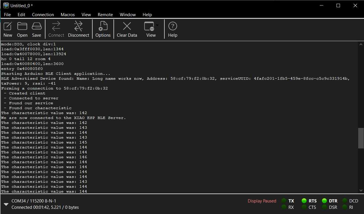
Bas saw that I kept manually switching COM ports in the Arduino IDE so I could open the serial monitor for the port I wanted, so he showed me Coolterm; this is a simple serial port terminal application that you can use to have multiple serial ports open at the same time. So now I had the Arduino serial monitor with my Bluetooth server open, and the Coolterm serial monitor with the Bluetooth client. Here you can see that I finally managed to send sensor data that was continuously updated!
Here the code for the BLE client:
/**
   A BLE client example that is rich in capabilities.
   There is a lot new capabilities implemented.
   author unknown
   updated by chegewara
   Modified by Michelle Vossen
*/

#include "BLEDevice.h"
//#include "BLEScan.h"


BLERemoteService* pRemoteService;
BLEClient*  pClient;

// The remote service we wish to connect to.
static BLEUUID serviceUUID("4fafc201-1fb5-459e-8fcc-c5c9c331914b");
// The characteristic of the remote service we are interested in.
static BLEUUID    charUUID("beb5483e-36e1-4688-b7f5-ea07361b26a8");

static boolean doConnect = false;
static boolean connected = false;
static boolean doScan = false;
static BLERemoteCharacteristic* pRemoteCharacteristic;
static BLEAdvertisedDevice* myDevice;

static void notifyCallback(
  BLERemoteCharacteristic* pBLERemoteCharacteristic,
  uint8_t* pData,
  size_t length,
  bool isNotify) {
  Serial.print("Notify callback for characteristic ");
  Serial.print(pBLERemoteCharacteristic->getUUID().toString().c_str());
  Serial.print(" of data length ");
  Serial.println(length);
  Serial.print("data: ");
  Serial.write(pData, length);
  Serial.println();
}

class MyClientCallback : public BLEClientCallbacks {
    void onConnect(BLEClient* pclient) {
    }

    void onDisconnect(BLEClient* pclient) {
      connected = false;
      Serial.println("onDisconnect");
    }
};

bool connectToServer() {
  Serial.print("Forming a connection to ");
  Serial.println(myDevice->getAddress().toString().c_str());

  pClient  = BLEDevice::createClient();
  Serial.println(" - Created client");

  pClient->setClientCallbacks(new MyClientCallback());

  // Connect to the remove BLE Server.
  pClient->connect(myDevice);  // if you pass BLEAdvertisedDevice instead of address, it will be recognized type of peer device address (public or private)
  Serial.println(" - Connected to server");
  pClient->setMTU(517); //set client to request maximum MTU from server (default is 23 otherwise)

  // Obtain a reference to the service we are after in the remote BLE server.
  pRemoteService = pClient->getService(serviceUUID);
  if (pRemoteService == nullptr) {
    Serial.print("Failed to find our service UUID: ");
    Serial.println(serviceUUID.toString().c_str());
    pClient->disconnect();
    return false;
  }
  Serial.println(" - Found our service");


  // Obtain a reference to the characteristic in the service of the remote BLE server.
  pRemoteCharacteristic = pRemoteService->getCharacteristic(charUUID);
  if (pRemoteCharacteristic == nullptr) {
    Serial.print("Failed to find our characteristic UUID: ");
    Serial.println(charUUID.toString().c_str());
    pClient->disconnect();
    return false;
  }
  Serial.println(" - Found our characteristic");

  // Read the value of the characteristic.
  if (pRemoteCharacteristic->canRead()) {
    std::string value = pRemoteCharacteristic->readValue();
    Serial.print("The characteristic value was: ");
    Serial.println(value.c_str());
  }

  if (pRemoteCharacteristic->canNotify())
    pRemoteCharacteristic->registerForNotify(notifyCallback);

  connected = true;
  return true;
}
/**
   Scan for BLE servers and find the first one that advertises the service we are looking for.
*/
class MyAdvertisedDeviceCallbacks: public BLEAdvertisedDeviceCallbacks {
    /**
        Called for each advertising BLE server.
    */
    void onResult(BLEAdvertisedDevice advertisedDevice) {
      Serial.print("BLE Advertised Device found: ");
      Serial.println(advertisedDevice.toString().c_str());

      // We have found a device, let us now see if it contains the service we are looking for.
      if (advertisedDevice.haveServiceUUID() && advertisedDevice.isAdvertisingService(serviceUUID)) {

        BLEDevice::getScan()->stop();
        myDevice = new BLEAdvertisedDevice(advertisedDevice);
        doConnect = true;
        doScan = true;

      } // Found our server
    } // onResult
}; // MyAdvertisedDeviceCallbacks


void setup() {
  Serial.begin(115200);
  while (!Serial) {
    ; // wait for serial port to connect. Needed for native USB port only
  }
  ESP32PWM::allocateTimer(0);
  ESP32PWM::allocateTimer(1);
  ESP32PWM::allocateTimer(2);
  ESP32PWM::allocateTimer(3);
  myservo.setPeriodHertz(50);    // standard 50 hz servo
  myservo.attach(servoPin, 1000, 2000); // attaches the servo on pin 18 to the servo object
  Serial.println("Starting Arduino BLE Client application...");
  BLEDevice::init("");

  // Retrieve a Scanner and set the callback we want to use to be informed when we
  // have detected a new device.  Specify that we want active scanning and start the
  // scan to run for 5 seconds.
  BLEScan* pBLEScan = BLEDevice::getScan();
  pBLEScan->setAdvertisedDeviceCallbacks(new MyAdvertisedDeviceCallbacks());
  pBLEScan->setInterval(1349);
  pBLEScan->setWindow(449);
  pBLEScan->setActiveScan(true);
  pBLEScan->start(5, false);
} // End of setup.


// This is the Arduino main loop function.
void loop() {

  // If the flag "doConnect" is true then we have scanned for and found the desired
  // BLE Server with which we wish to connect.  Now we connect to it.  Once we are
  // connected we set the connected flag to be true.
  if (doConnect == true) {
    if (connectToServer()) {
      Serial.println("We are now connected to the XIAO ESP BLE Server.");
    } else {
      Serial.println("We have failed to connect to the server; there is nothing more we will do.");
    }
    doConnect = false;
  }

  // If we are connected to a peer BLE Server, update the characteristic each time we are reached
  // with the current time since boot.
  if (connected) {
    // Read the value of the characteristic.
    if (pRemoteCharacteristic->canRead()) {
      std::string value = pRemoteCharacteristic->readValue();
      Serial.print("The characteristic value was: ");
      Serial.println(value.c_str());
    }
    pRemoteCharacteristic->writeValue("Hello");
  } else if (doScan) {
    BLEDevice::getScan()->start(0);
  }

  delay(1000); // Delay a second between loops.
} // End of loop
And here for the server:
/*
Based on Neil Kolban example for IDF: https://github.com/nkolban/esp32-snippets/blob/master/cpp_utils/tests/BLE%20Tests/SampleServer.cpp
Ported to Arduino ESP32 by Evandro Copercini
updates by chegewara
*/
#include <BLEDevice.h>
#include <BLEUtils.h>
#include <BLEServer.h>
const int sensorPin = 2; // pin that the sensor is attached to
const int ledPin = 3; // pin that the LED is attached to
int sensorValue = 0; // the sensor value
int sensorMin = 1023; // minimum sensor value
int sensorMax = 0; // maximum sensor value
BLEServer *pServer;
BLEService *pService;
BLECharacteristic *pCharacteristic;
// See the following for generating UUIDs:
// https://www.uuidgenerator.net/
#define SERVICE_UUID "4fafc201-1fb5-459e-8fcc-c5c9c331914b"
#define CHARACTERISTIC_UUID "beb5483e-36e1-4688-b7f5-ea07361b26a8"
void setup() {
Serial.begin(115200);
// while (!Serial) {
// ; // wait for serial port to connect. Needed for native USB port only
// }
pinMode(ledPin, OUTPUT);
pinMode(sensorPin, INPUT);
Serial.println("Starting BLE work!");
BLEDevice::init("Long name works now");
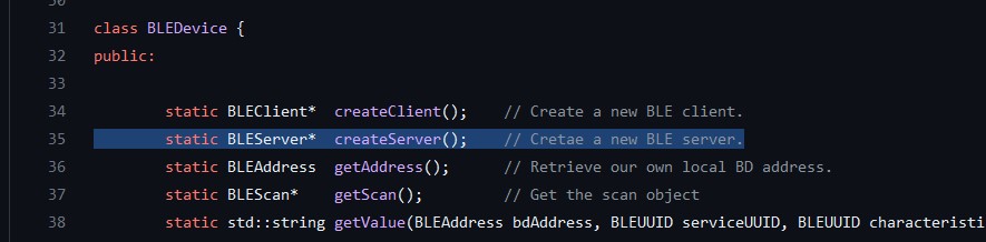
// C++ code: in class BLEDevice we call createServer(); this method returns a pointer (=address)
// of type BLEServer and we store that in a variable named pServer of type pointer to BLEServer
// (BLEServer *).
pServer = BLEDevice::createServer();
pService = pServer->createService(SERVICE_UUID);
pCharacteristic = pService->createCharacteristic(
CHARACTERISTIC_UUID,
BLECharacteristic::PROPERTY_READ |
BLECharacteristic::PROPERTY_WRITE
);
pService->start();
// BLEAdvertising *pAdvertising = pServer->getAdvertising(); // this still is working for backward compatibility
BLEAdvertising *pAdvertising = BLEDevice::getAdvertising();
pAdvertising->addServiceUUID(SERVICE_UUID);
pAdvertising->setScanResponse(true);
pAdvertising->setMinPreferred(0x06); // functions that help with iPhone connections issue
pAdvertising->setMinPreferred(0x12);
BLEDevice::startAdvertising();
Serial.println("Characteristic defined");
}
void loop() {
Serial.println("start");
digitalWrite(ledPin, HIGH);
for (int timems = 0; timems < 5000; timems++) {
sensorValue = analogRead(sensorPin);
// record the maximum sensor value
if (sensorValue > sensorMax) {
sensorMax = sensorValue;
}
// record the minimum sensor value
if (sensorValue < sensorMin) {
sensorMin = sensorValue;
}
delay(1);
}
// signal the end of the calibration period
digitalWrite(ledPin, LOW);
Serial.print("Results: ");
Serial.print(sensorMin);
Serial.print("\t");
Serial.println(sensorMax);
for (int i = 0; i < 10000; i++) { // output
sensorValue = analogRead(sensorPin);
// Serial.println(sensorValue);
// in case the sensor value is outside the range seen during calibration
sensorValue = constrain(sensorValue, sensorMin, sensorMax);
// apply the calibration to the sensor reading
sensorValue = map(sensorValue, sensorMin, sensorMax, 0, 180);
String valueString = String(sensorValue);
Serial.println(valueString);
pCharacteristic->setValue(valueString.c_str()); // expects 0 terminated string, converts String to c_str which is a character array
pCharacteristic->notify();
// fade the LED using the calibrated value:
analogWrite(ledPin, sensorValue);
delay(1);
}
}
Programming explanation by Pieter and Bas
Data enters from a network, this data has to be saved somewhere. This is saved in a buffer which is usually an array (char array). An array is addressable.

Microcontroller tries to read data from a non-existing address > null pointer exception

Class:
Method: something with brackets that returns nothing (void blabla()) or one thing (int blabla()).
If you want return multiple things you need a struct <https://forum.arduino.cc/t/using-struct/42793/2>
struct person *get

struct is a class

pointer: *bla (points to address of variable)
int *address > address to an int, the asterisk is part of the int * not of address
address: &bla (address of variable)

primitives: int, float, char
non-primitives: struct, arrays

Remember: true data (ints, floats) and addresses to data are different things

dot notation for a pointer is -> (.bla)

referencing dereferencing
every byte has an address

* (uint32_t *) inputbuffer

Inputbuffer is a pointer of a specific type
The part in between brackets is a type cast that now specifies that the type of inputbuffer becomes the type pointer to uint32_t (it was an array before but now it's interpreted as an 32 bit int address).
The asterisk in front **dereferences** this pointer to the value instead of the address of that value.

struct person *p2;
p2 = &p1 // variable p2 is the address of p1 (not the value)
If you then want the value at that address:
(*p2).age is the same as p2 -> age, it's a socalled synthectic shooter, it's easier than the dot notation.

char *myString is an address of

Iets tussen haakjes zetten zoals (int) is typecasten naar int (in dit geval)

ASCII: for people
Binary: for computers
Links:
- https://www.arduino.cc/reference/en/language/structure/pointer-access-operators/reference/
- https://forum.arduino.cc/t/sending-data-from-esp32-with-ble-in-my-phone/676015/6
- https://randomnerdtutorials.com/esp32-bluetooth-low-energy-ble-arduino-ide/
- https://stackoverflow.com/questions/60452786/best-way-to-send-float-values-over-ble
- https://github.com/espressif/arduino-esp32/issues/1153
BLE / Bluetooth on the XIAO
Somewhere during the week I tried to understand the code I was using before to modify it to send my sensor readings from the XIAO to the WROOM. I just don’t understand it so far so I wanted to switch to classic Bluetooth which is more suitable for my purposes anyway I think.
However, as soon as I decided that, I learned that the ESP32C3 only supports BLE, not BT Classic. Thanks again, XIAO.
Group assignment
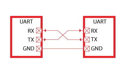
For the group assignment this week, we have to send a message between two projects. We wanted to do multiple communication methods since we were very optimistic, but in the end we only had time for serial communication with TX and RX between two boards.
UART
We started out with two ESP32’s and this tutorial. However something very simple resulted in an immediate error in my Arduino IDE that I hadn’t seen before. I couldn’t upload to the ESP nor update nor remove the esp32 board library. In the end I had to reinstall the Arduino IDE (I went from 1.8.16 to 1.8.19; I don’t want to go to 2.x.x because I dislike the new interface).

In the meantime we set up serial communication between two Arduino’s. From the Arduino Uno connected on my side, we sent a 1 and a 0 with a delay of 1000ms in between to the serial monitor. We had an LED connected to the other Arduino, and we wanted to use the Uno to blink this LED. We also had the logic analyzer connected to see the data sent. This should be really simple.
We first tried to get an Arduino Uno to communicate with an Arduino Leonardo, but we received no data. After a long troubleshooting session and no improvement we learned that the RX pin on the Leonardo didn’t work. When we swapped it out with another Arduino Uno the LED blinked right away.
Code
Main code:
void setup()
{
  Serial.begin(115200);
}
void loop()
{
  Serial.print("1");
  delay(1000);
  Serial.print("0");
  delay(1000);
}
Secondary code:
char number  = ' ';
int LED = 5;

void setup()
{
  Serial.begin(115200);
  pinMode(LED, OUTPUT);
}
void loop()
{
  if (Serial.available());
  {
    char number = Serial.read();
    if (number == '0') {
      digitalWrite(LED, LOW);
    }
    if (number == '1') {
      digitalWrite(LED, HIGH);
    }
  }
}
Links
Files
Erwin’s lecture notes
OSI layers: netwerk layers needed internet draait volledig op tcp maar dat kun je doen over allerlei verschillende fysieke lagen (radio, wifi, kabels, satteliet etc)
OSI layers 7: application (HTTP) 6: presentation (SSL) 5: session (RPC) 4: transport (TCP, UDP) 3: network (IP) 2: data link (MAC) 1: physical (PHY)
Zandloper vorm: veel applications en dingen richting de fysieke layer en application layer, maar middelste layer is (bijna) altijd TCP/IP: transmission control protocol/internet protocol
- Very resistant tegen knooppunten die halverwege uitvallen, for very resilient communication
- IP address is routable, can talk with each other via a route over the network
- 10:… addresses aren’t used on the internet (convention)
- IPv4: 4 bytes, network address translation
- IPv6 is 16 bytes (more addresses than grains of sand on earth)
- Subnets
Ethernet
- MAC address (media access control)
Protocollen UART Universal asynchronous receive & transmit
- No clock
- Rx / Tx with a fixed speed (something you agree beforehand)
- Synchronization rules > baud rates
- 9600, 8, n, 1 = 9600 bit/second (plus de twee hierna, dus uiteindelijk 960 bytes per seconde) 8 data bits, no parity bit (error detection, not error correction, that happens on higher OSI layers), 1 stop bit (can also be 2) Examples:
- RS232: UART with +/- 15V
- RS485: UART with differential signals & twisted wires for lower EMC (electromagnetic current)
Unicast: sending to one Multicast/broadcast: sending to multiple
SPI
- MISO, MOSI, CS, CLK, GND
- Clock signal makes sure there is data synchronization
- MISO / MOSI main/secondary exchange of data
- High data rate, very fast
- Use chip select (CS) to specify which receiver to talk to
- Complications: can get a little tricky with programming
- Controller is de MI en de MO, receivers doen SI en SO. CS low = active
- Pas bij het omhoog gaan van de clock lees je de data, op de neergaande stuur je de data Examples:
- Memory cards
- GPIO expander
- Daisy-chaining: send all data in one stream to all receivers; MISO/MOSI chaining; example is NeoPixels
I2C = TWI
- SCK, SDA, GND
- Sending and receiving on the same SDA line
- I2C scanner library > scans all I2C addresses and checks whether any address answers (ack/nack)
- You can use standard I2C library and then configure the devices, often another library
- Pas bij het omhoog gaan van de clock lees je de data, op de neergaande stuur je de data (afhankelijk van het protocol)
- Every receiver has their own address; 7-bit address (or 10-bit address) is mostly fixed unless you are defining your own I2C devices
- Good practice to fix bus levels to ensure a valid signal;
- Rule of thumb: SPI 10kOhm pull down resistor (mode 0), I2C 4,7kOhm pullup resistor, from VCC to both SCK & SDA
- Level shifting 3.3V to 5V sometimes necessary, can do this with a mosfet
Bus termination for really long wires a wire acts as a capacitor with a resistor
Lecture notes
Why network?
- Location
- Parallelism: you need to do many things at the same time; separate processors for separate tasks
- Modularity
- Interference
Wired
- Asynchronous: TX RX
- Multi drop: transmit is easy, all the devices listen (hardcoded identities, figure out who talks when. A simple way to do this is with input tristate).
- Bus network transmit and receive wires; host in charge and assign addresses and hang them off the bus (max 10 processors).
SPI (serial peripheral interface)
- 3 wires
- MISO & MOSI > CIPO & COPI (controller/peripheral)
- SD memory card
- Clock line tells you when the bit comes by
- See examples with Arduino library; there is also examples that do everything in software so you can use any chip
- FAT formatting is messy and ancient but widely used
- Uses: data logging (non-volatile), audio (WAV)
I2C
- 2 wire interface
- More popular now than SPI: I2C has lots of use cases
- Initially between two processors but can be used for all kinds of devices
- Easy to do with bitbanging (not a good idea if the processor is busy but can do it on any pin and any processor)
- 2 resistors in I2C: pull-up resistors that hold it up
- Even if you have a pull-up in the chip, if it’s 75k it’s too high and makes it too slow, that’s why you use it
- Power consumption doesn’t differ much between SPI and I2C
USB
- UART
- Language of serial interfaces
- HID
- You can make anything act like a user interface / MIDI / keyboard / mouse / your device as a host
- Ethernet: not very common anymore
The difference between a bus and a network is that in a network there is topology; routes
Physical media
Bits of second depends on how strong your signal is compared to the noise and to the frequency
Physical media, wired Transmission line: thick wire that guides the signal Waveguide: a tube that guides it Optical: fiber that guides it
Wireless
- RF (radio frequency); plenty live in ISM
- WIFI
- Bluetooth
- etc.
- Optical: using light to send signals by modulating it
- Acoustic
Radio
- Modulating the radio wave on board
-
To talk to a radio you need an antenna and a chip
- RFID, a wire through the air
- Bluetooth modules or integrated