Week 11: Input Devices
Checklist for this week:
- ☑ Linked to the group assignment page
- ☑ Documented what you learned form interfacing an input device(s) to microcontroller and how the physical property relates to the measured results
- ☑ Documented your design and fabrication process or linked to the board you made in a previous assignment
- ☑ Explained the programming process/es you used
- ☑ Explained any problems you encountered and how you fixed them
- ☑ Included original design files and source code
- ☑ Included a 'hero shot' of your board
Group Assignments
- Probe an input device(s)'s analog and digital signals
- Document your work on the group work page and reflect what you learned on your individual page
Individual Assignments
- Measure something: add a sensor to a microcontroller board that you have designed and read it
Hero Shot
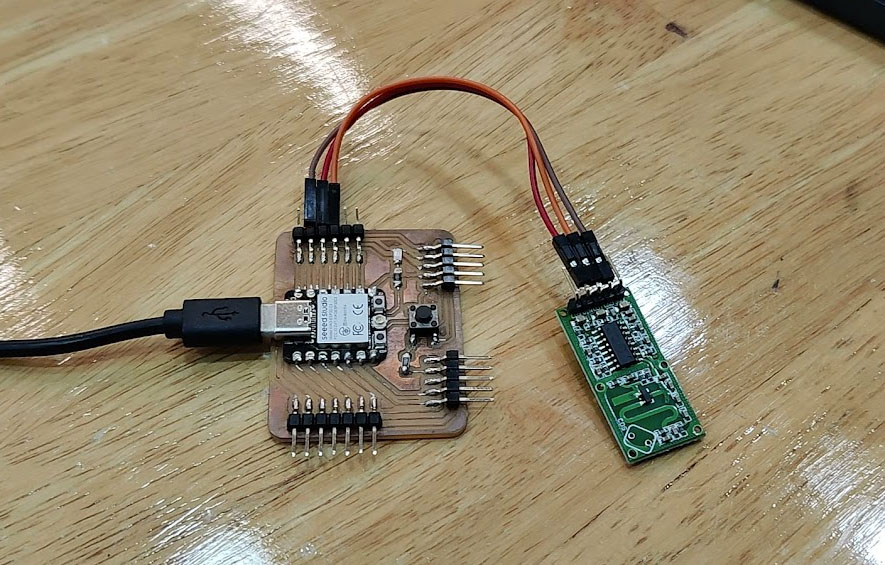
For the input sensor, I choose the Microwave Doppler Radar motion sensor (RCWL-0516) and use the XIAO ESP32C3 PCB board that I have produced previously to detect motion and read it on a serial monitor. The design and production of the PCB Board to shield the XIAO ESP32C3 is documented in Week 6 and week 8.
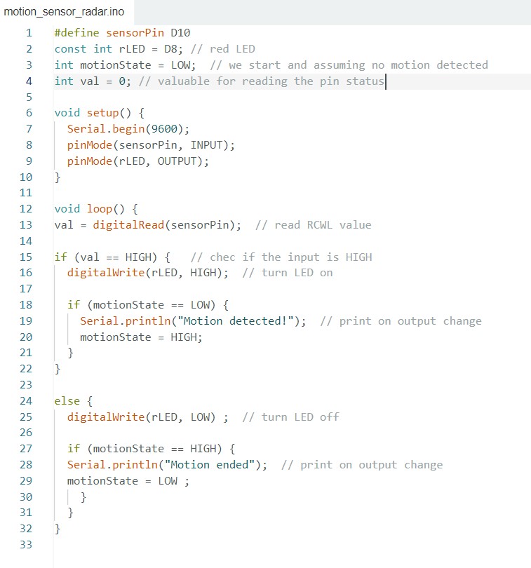
This is the reference material for the sample Arduino code on the RCWL-0516 from the site "Last Minute Engineering". After the hero shot is the Arduino code for the working sensor shown in the video.
The process of connecting the components was straightforward due to the deliberate exposure of all microcontroller pins in the PCB design. Additionally, there was a readily accessible 5V power outlet. I successfully established connections by linking the ground, the 5V power supply, and a signal pin ( D10).
Upon detecting movement, the serial terminal promptly presents the message "Motion detected!" and the LED on the PCB board light up. Conversely, when no movement is detected, the printed message switches to "Motion ended".
Due to its high sensitivity, the sensor detects movement and triggers the light to turn on even before the hand, which initiates the movement, becomes visible on the screen.
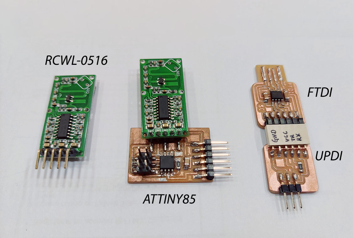
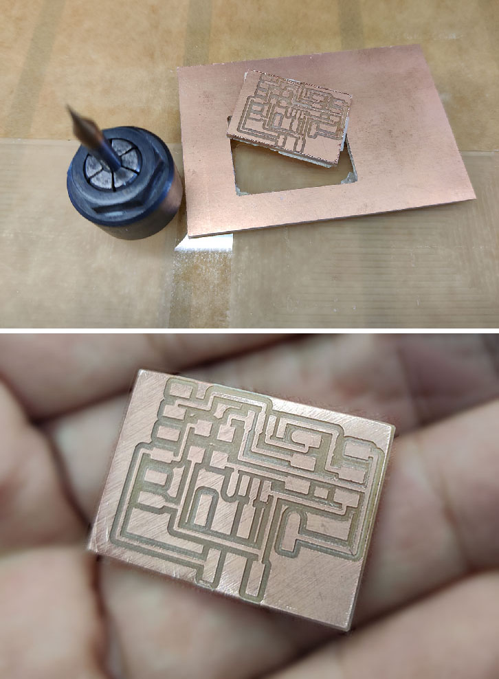
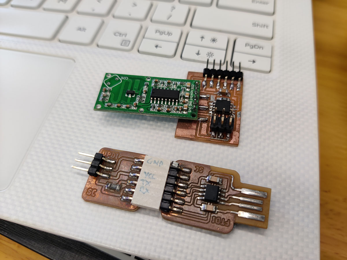
Problems I encountered: RCWL-0516 and ATtiny85
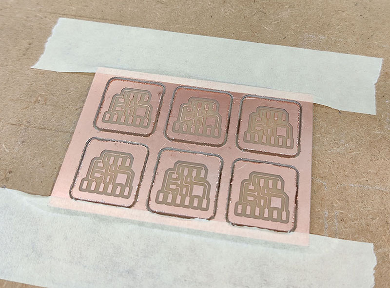
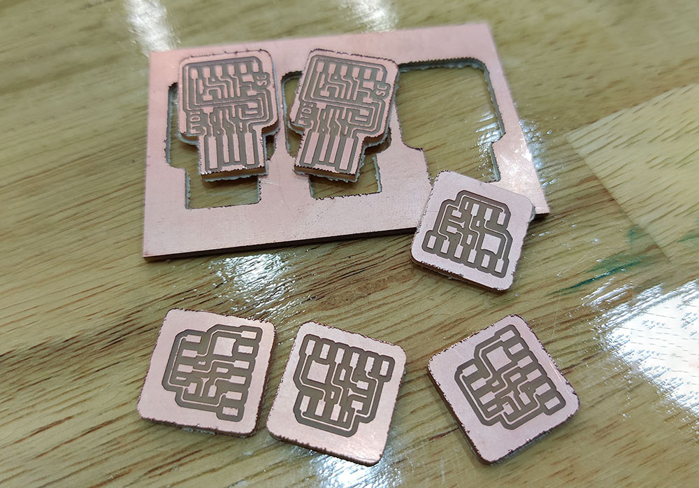
To dive deeper into the topic, I follow the schematic from Professor Neil's page and make another board with ATtiny chip to solder the RCWL onto. But instead of ATtiny45, I replace it with ATtiny85.
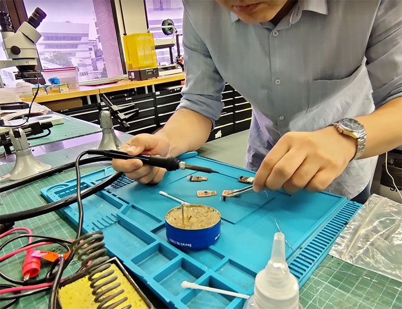
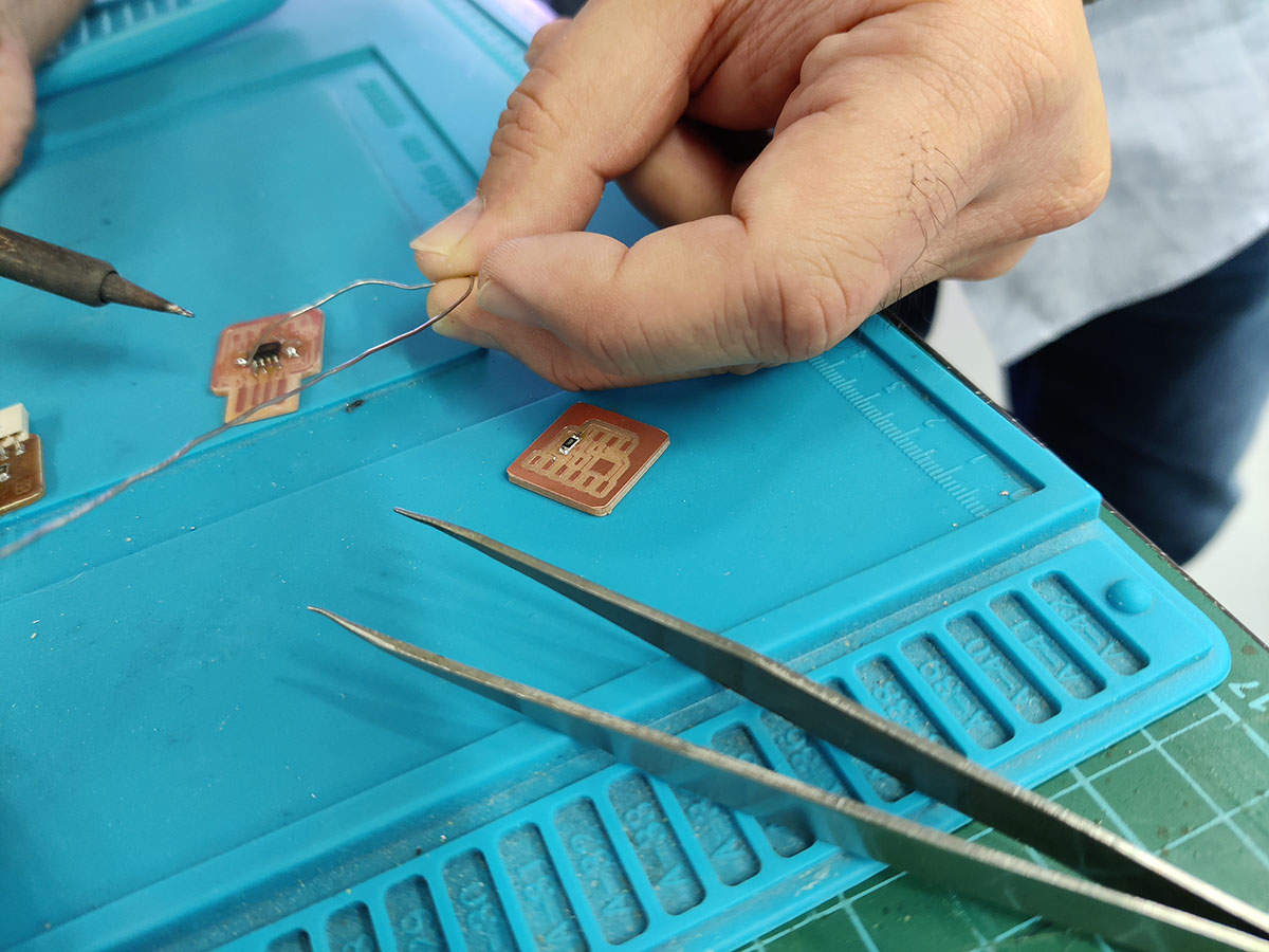
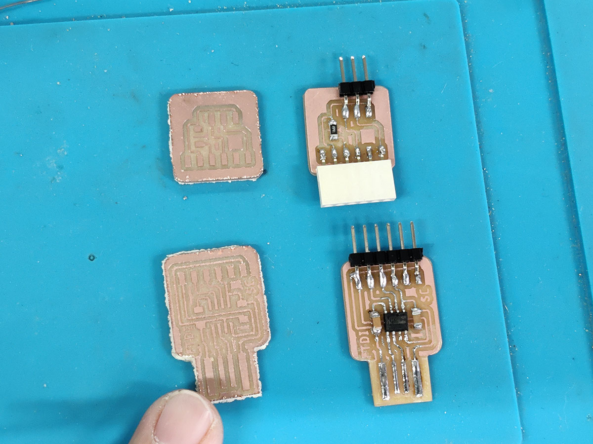
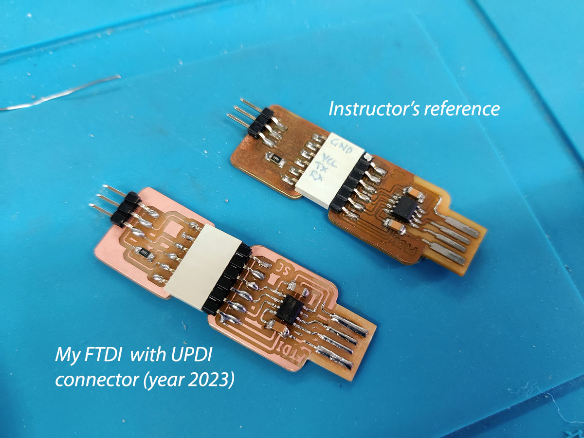
After finishing the board with ATtiny85, I learn that ATtiny85 doesn't have a bootloader and I would need to make another FTDI board to load the code through USB. Next, I mill out 3 sets FTDI with UPDI connectors and solder all the components on it using our instructor's schematic.
The FTDI is currently on spiral development.
Measuring the Motion Sensor Signals
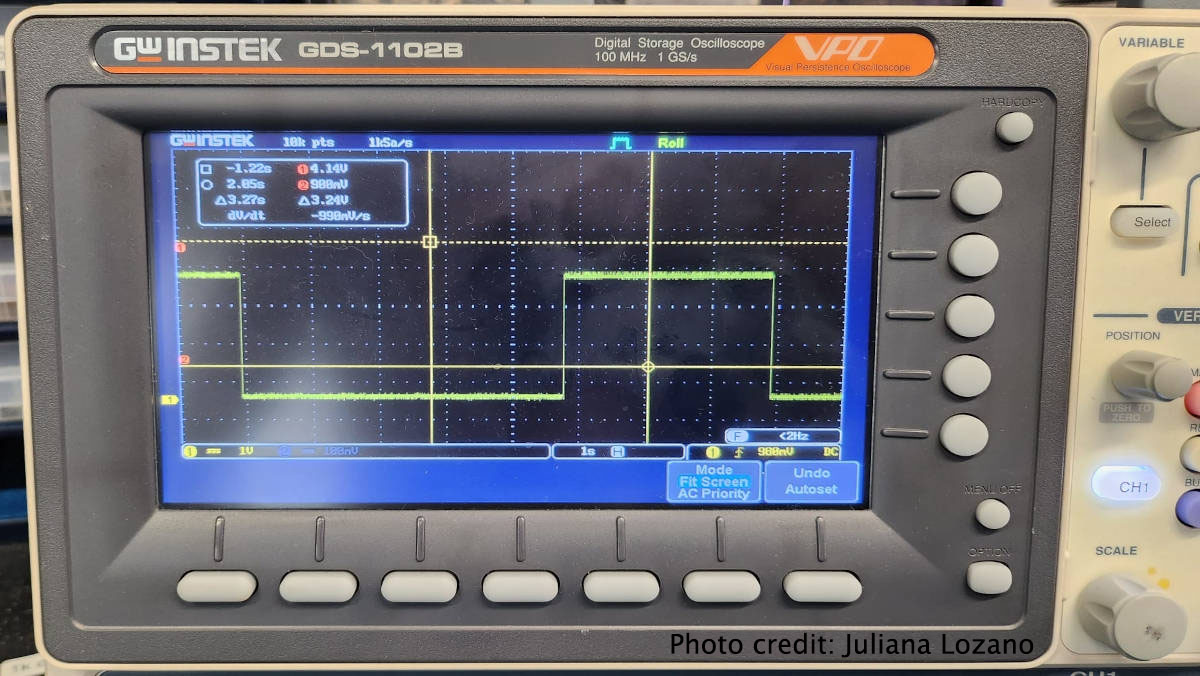
Upon successfully uploading the code to the microcontroller, we proceeded to measure the signals from the sensor. To achieve this, I connected the PCB to a 5V battery while maintaining the same sensor connections. However, this time, I utilized an oscilloscope by connecting it to the signal pin (D10) and grounding it on the PCB using a probe set.
Our observation on the oscilloscope screen revealed waveform patterns that correlated with the sensor's output. These waveforms manifested as either a HIGH signal (indicating the detection of movement) or a LOW signal (indicating the absence of movement).
Notably, we observed that the height and duration of the signal remained constant when movement was detected, lasting for 2 seconds. Conversely, the duration of the LOW signal varied, signifying no movement.
Microwave Doppler Radar sensor vs PIR sensor
Here is a good reading from www.rfwireless-world.com.
Microwave Doppler Radar motion sensors and PIR motion sensors can be compared based on several parameters. Radar sensors are active and use electromagnetic waves, offering a larger detection range, better resolution, precise identification, and superior penetration capabilities. They also exhibit resistance to moisture, dirt, and temperature. However, they tend to be more expensive. On the other hand, PIR sensors are passive and use infrared waves. They have a relatively shorter detection range, lower resolution, less precise identification, poorer material penetration, and lower resistance to environmental factors. PIR sensors are generally cheaper but have weaker speed detection and accuracy sensitivity compared to radar sensors.
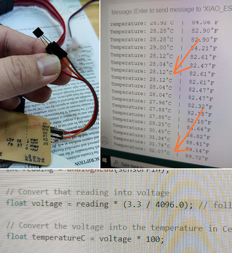
LM35 temperature sensor with XIAO ESP32C3
During the week, the instructor mentioned about the temperature sensor LM35. I put the arduino code in my XIAO pcb board and it works.
Arduino code reference here from "www.esp32learning.com".
After uploading the code to the board, I successfully established a connection with the sensor by utilizing Pin A0 (Analog). This enabled me to read signals from the sensor and gather valuable data.
In the photo provided, a noticeable difference in temperature can be observed depending on whether the sensor is held in the palm or not. When the sensor is held in the palm, the temperature appears to be higher compared to when it is not in contact with the hand. This temperature variation is likely due to the transfer of heat from the hand to the sensor, resulting in an elevated temperature reading.
Links to working files
- Motion Sensor Code 1 -ino format.
- Motion Sensor Code 2 -ino format.
- LM35 Temperature sensor Code with ESP32 -ino format.