6. Electronics design
This week we used different measurement tools for example Oscilloscope, Multimeter, in order to obsrve the operation and functioning of a microcontroller working. We also design a PCB of development target with a ESP32 microcontroller using Fusion 360 software
Oscilloscope use
In this video a short explanation of how the oscilloscope is used, we are measuring signals from ESP32 microcontroller.
Multimeter use
In this video a short explanation of how the multimeter is used, we measuring voltages from ESP32 microcontroller.
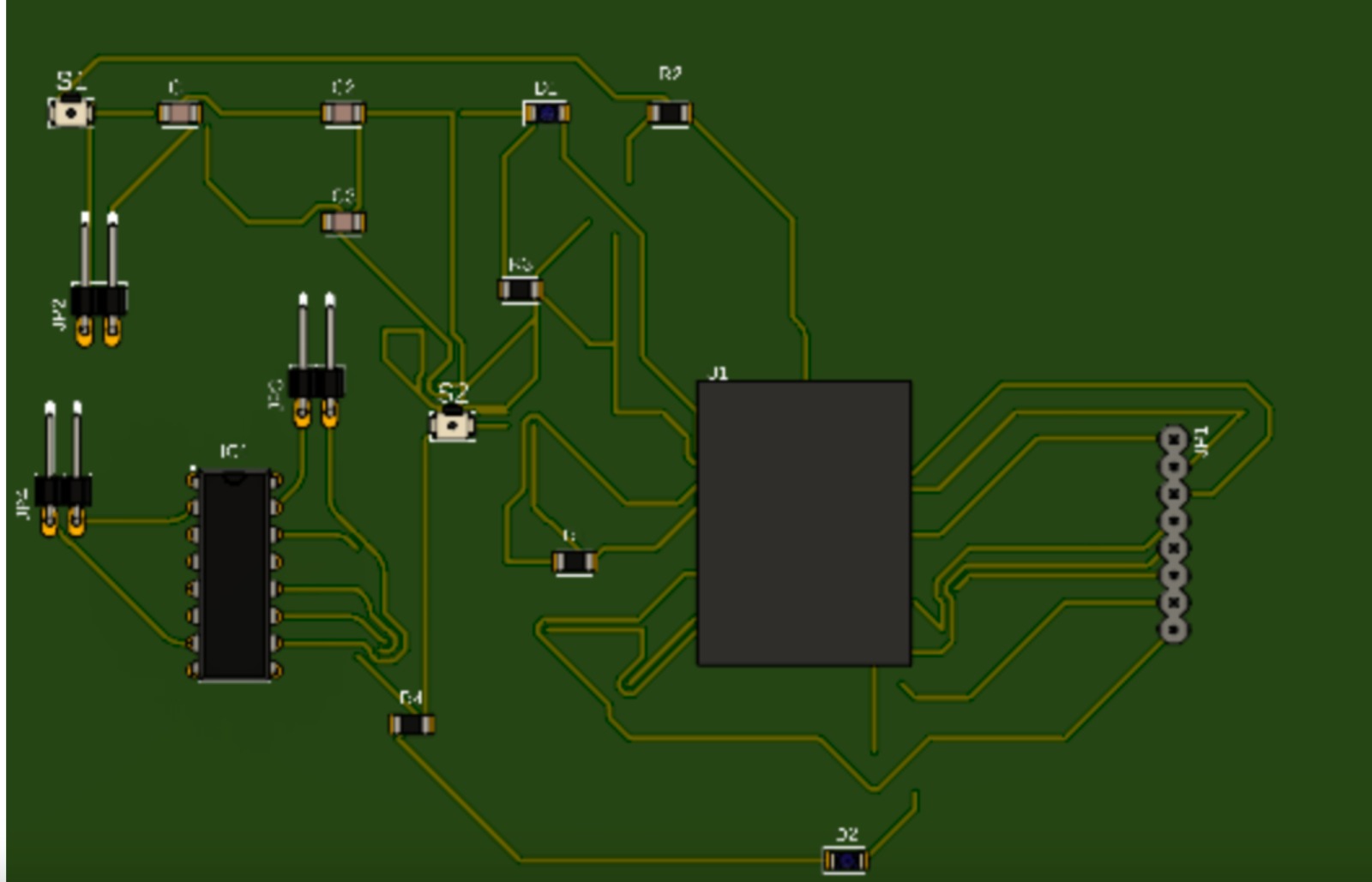
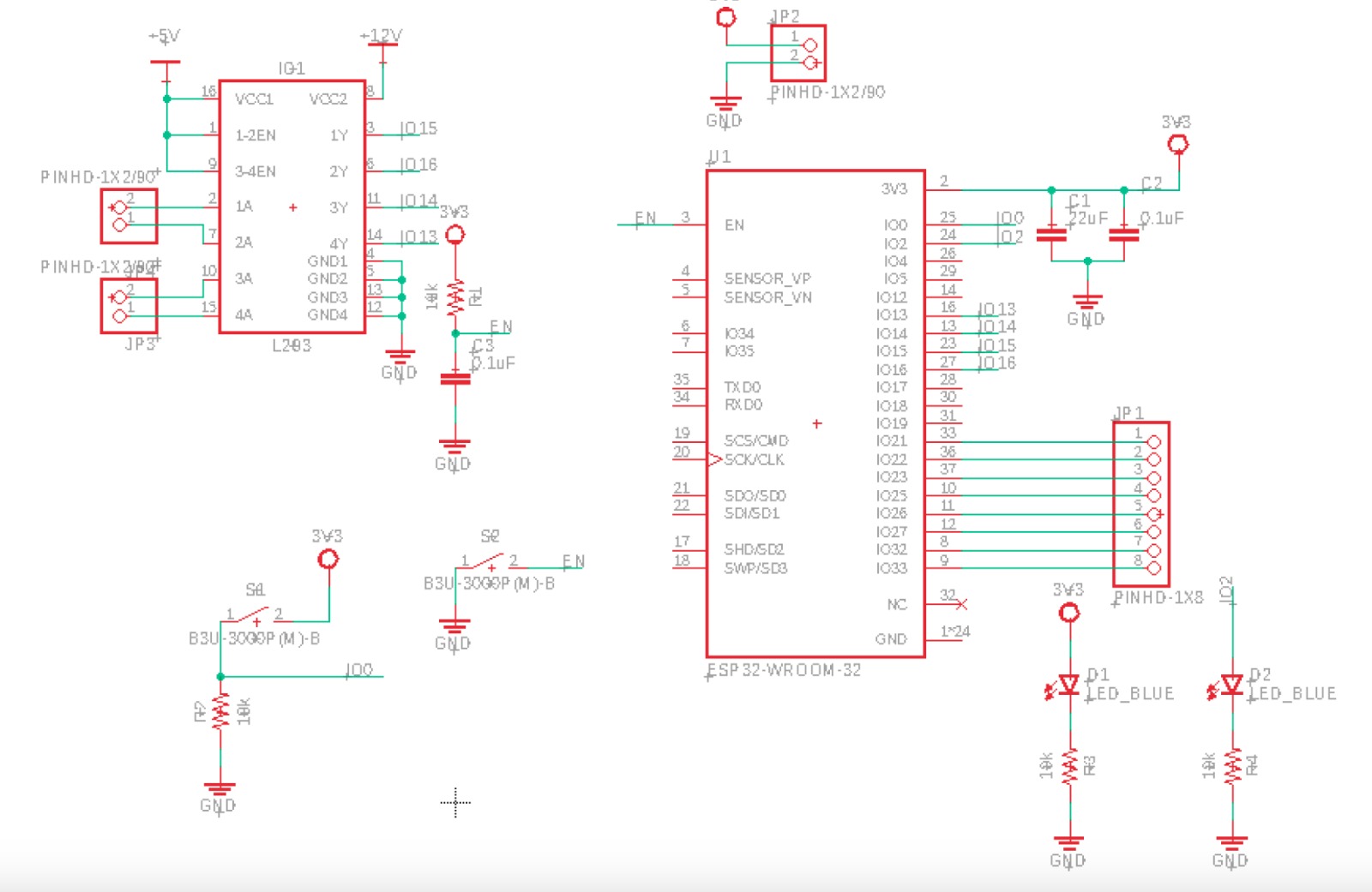
PCB of development target with a ESP32 microcontroller
The software used to design the PCB target is Fusion 360, this software include a electronics design tool
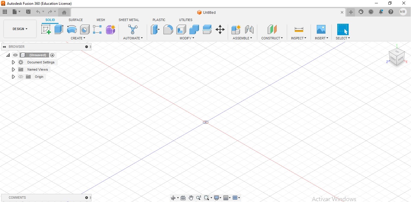
We open the software Fusion 360
The main window of Fusion 360
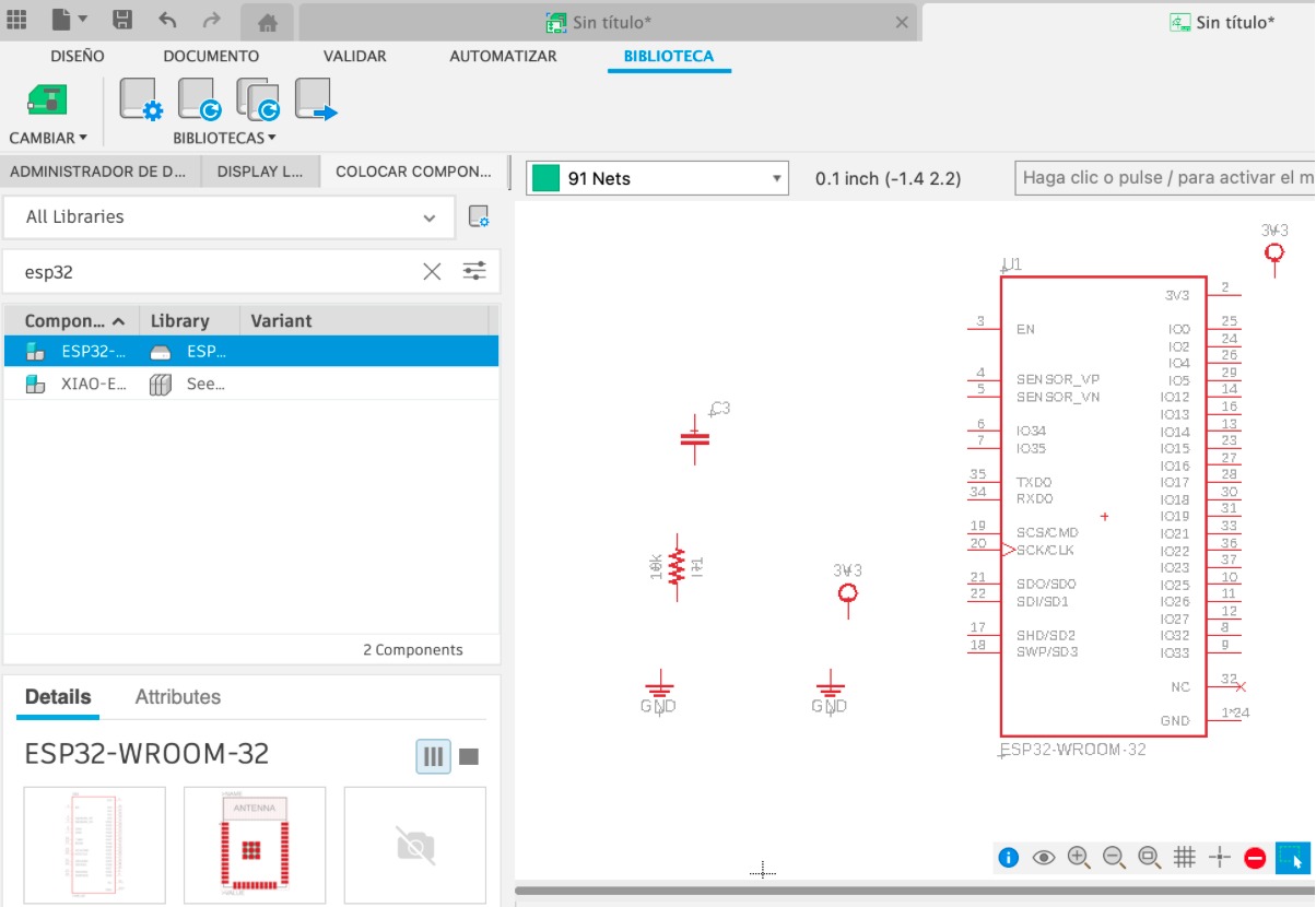
We select the Electronics design tool
You can see what you choose from the library in the electrical schematic
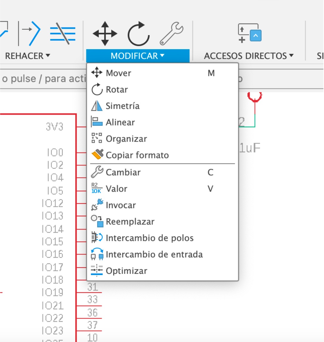
You can modify the value and position and
other functions in the upper bar by click on modify
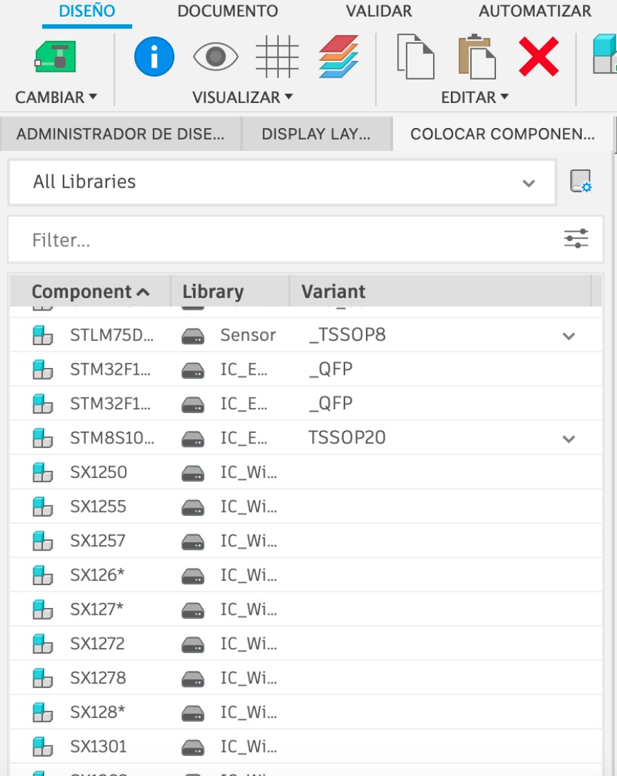
Here is what you have in your library
This screen shows you yor works
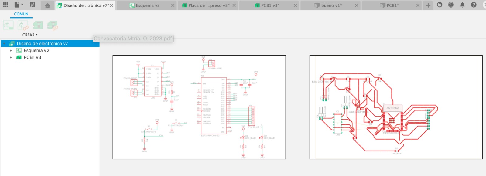
We create the electrical schematic design
This screen shows you yor works
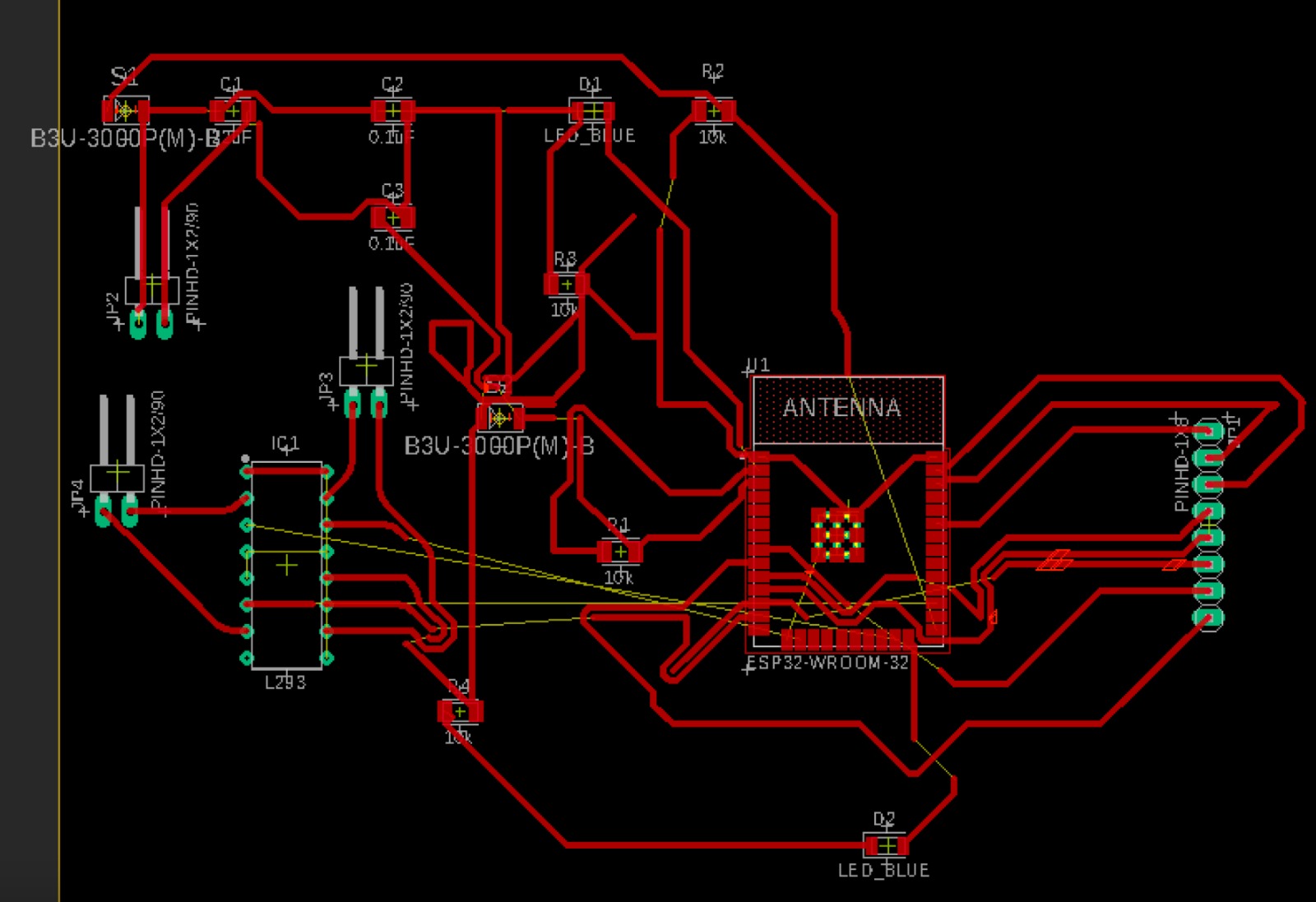
We create the electrical schematic design