4. Embedded programming
This week we programming diffetent kind of development kit in order to compare its main features and functionality. we will identify features that could be used in our final proyect.
ESP32 FEATURES
ESP32 is a single 2.4 GHz Wi-Fi-and-Bluetooth combo chip designed with the TSMC low-power 40 nm technology. It is designed to achieve the best power and RF performance, showing robustness, versatility and reliability in a wide variety of applications and power scenarios. The ESP32 series of chips includes ESP32-D0WD-V3, ESP32-D0WDR2-V3, ESP32-U4WDH, ESP32-S0WD (NRND), ESP32-D0WDQ6-V3 (NRND), ESP32-D0WD (NRND), and ESP32-D0WDQ6 (NRND), among which, • ESP32-S0WD (NRND), ESP32-D0WD (NRND), and ESP32-D0WDQ6 (NRND) are based on chip revision v1 or chip revision v1.1. • ESP32-D0WD-V3, ESP32-D0WDR2-V3, ESP32-U4WDH, and ESP32-D0WDQ6-V3 (NRND) are based on chip revision v3.0 or chip revision v3.1. For details on part numbers and ordering information, please refer to Section 7. For details on chip revisions, please refer to ESP32 Chip Revision v3.0 User Guide and ESP32 Series SoC Errata.
UltraLowPower Solution
ESP32 is designed for mobile, wearable electronics, and Internet-of-Things (IoT) applications. It features all the state-of-the-art characteristics of low-power chips, including fine-grained clock gating, multiple power modes, and dynamic power scaling. For instance, in a low-power IoT sensor hub application scenario, ESP32 is woken up periodically only when a specified condition is detected. Low-duty cycle is used to minimize the amount of energy that the chip expends. The output of the power amplifier is also adjustable, thus contributing to an optimal trade-off between communication range, data rate and power consumption.
Complete Integration Solution
ESP32 is a highly-integrated solution for Wi-Fi-and-Bluetooth IoT applications, with around 20 external components. ESP32 integrates an antenna switch, RF balun, power amplifier, low-noise receive amplifier, filters, and power management modules. As such, the entire solution occupies minimal Printed Circuit Board (PCB) area. ESP32 uses CMOS for single-chip fully-integrated radio and baseband, while also integrating advanced calibration circuitries that allow the solution to remove external circuit imperfections or adjust to changes in external conditions. As such, the mass production of ESP32 solutions does not require expensive and specialized Wi-Fi testing equipment.
WiFi Key Features
- 802.11b/g/n.
- 802.11n (2.4 GHz), up to 150 Mbps.
- WMM.
- TX/RX A-MPDU, RX A-MSDU.
- Immediate Block ACK.
- Defragmentation.
- Automatic Beacon monitoring (hardware TSF).
- 4 x virtual Wi-Fi interfaces.
- Simultaneous support for Infrastructure Station, SoftAP, and Promiscuous modes Note that when ESP32 is in Station mode, performing a scan, the SoftAP channel will be changed.
- Antenna diversity.
Bluetooth Key Features
- Compliant with Bluetooth v4.2 BR/EDR and Bluetooth LE specifications
- Class-1, class-2 and class-3 transmitter without external power amplifier
- Enhanced Power Control
- +9 dBm transmitting power.
- NZIF receiver with -94 dBm Bluetooth LE sensitivity
- Adaptive Frequency Hopping (AFH)
- Standard HCI based on SDIO/SPI/UART
- High-speed UART HCI, up to 4 Mbps
- Bluetooth 4.2 BR/EDR and Bluetooth LE dual mode controller
- Synchronous Connection-Oriented/Extended (SCO/eSCO)
- CVSD and SBC for audio codec
- Bluetooth Piconet and Scatternet
- Multi-connections in Classic Bluetooth and Bluetooth LE
- Simultaneous advertising and scanning
Advanced Peripheral Interfaces
- 34 x programmable GPIOs
- 12-bit SAR ADC up to 18 channels
- 2 x 8-bit DAC
- 10 x touch sensors
- 4 x SPI
- 2 x I2S
- 2 x I2C
- 3 x UART
- 1 host (SD/eMMC/SDIO)
- 1 slave (SDIO/SPI)
- Ethernet MAC interface with dedicated DMA and IEEE 1588 support
- TWAI®, compatible with ISO 11898-1 (CAN Specification 2.0)
- RMT (TX/RX)
- Motor PWM
- LED PWM up to 16 channels
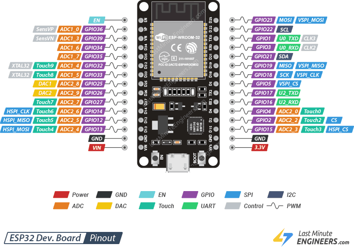
ESP32 Pinout
Programing the ESP32 using ARDUINO IDE
We use the ARDUINO IDE due to it is easy to use and really intuitive.
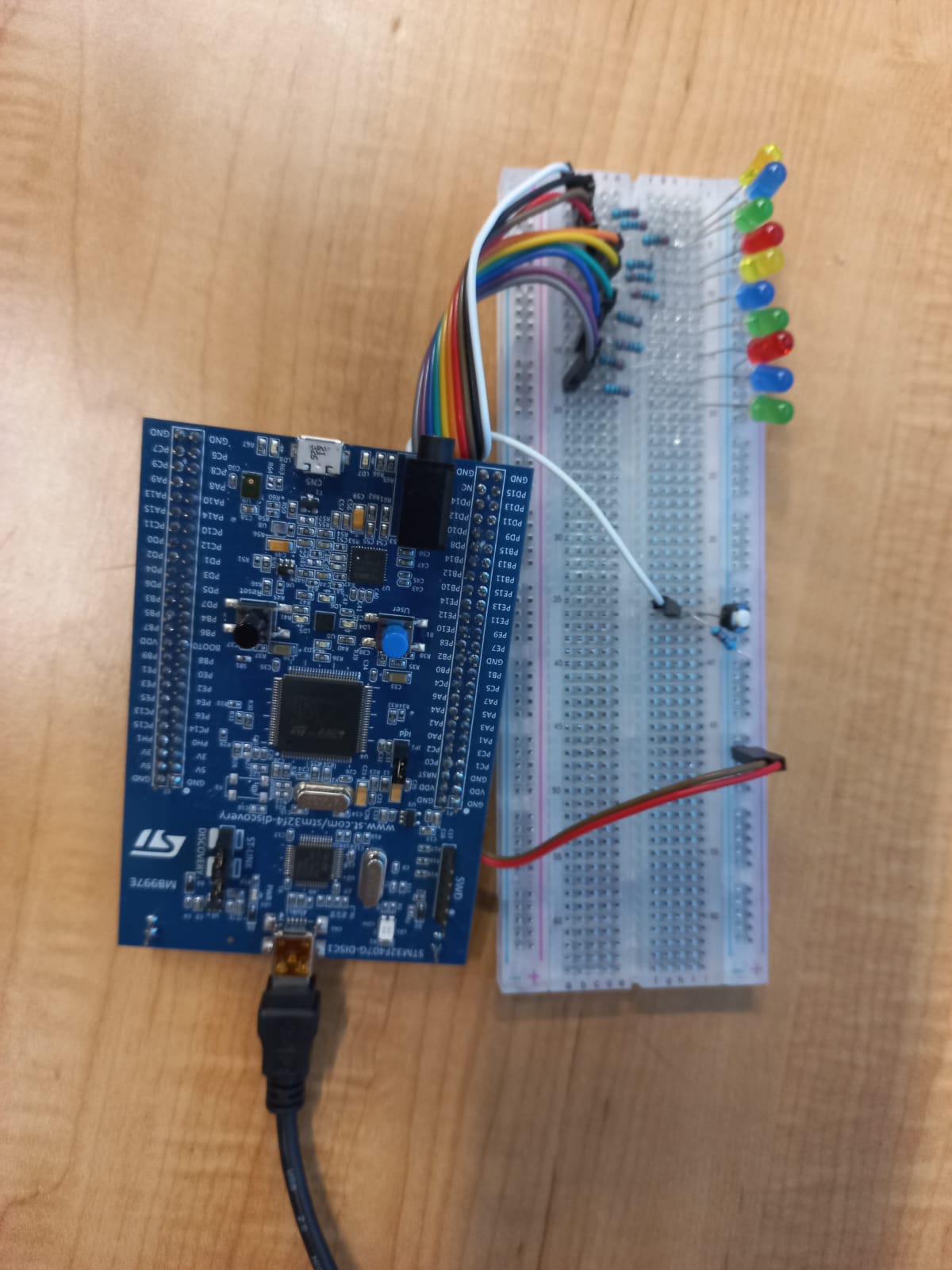
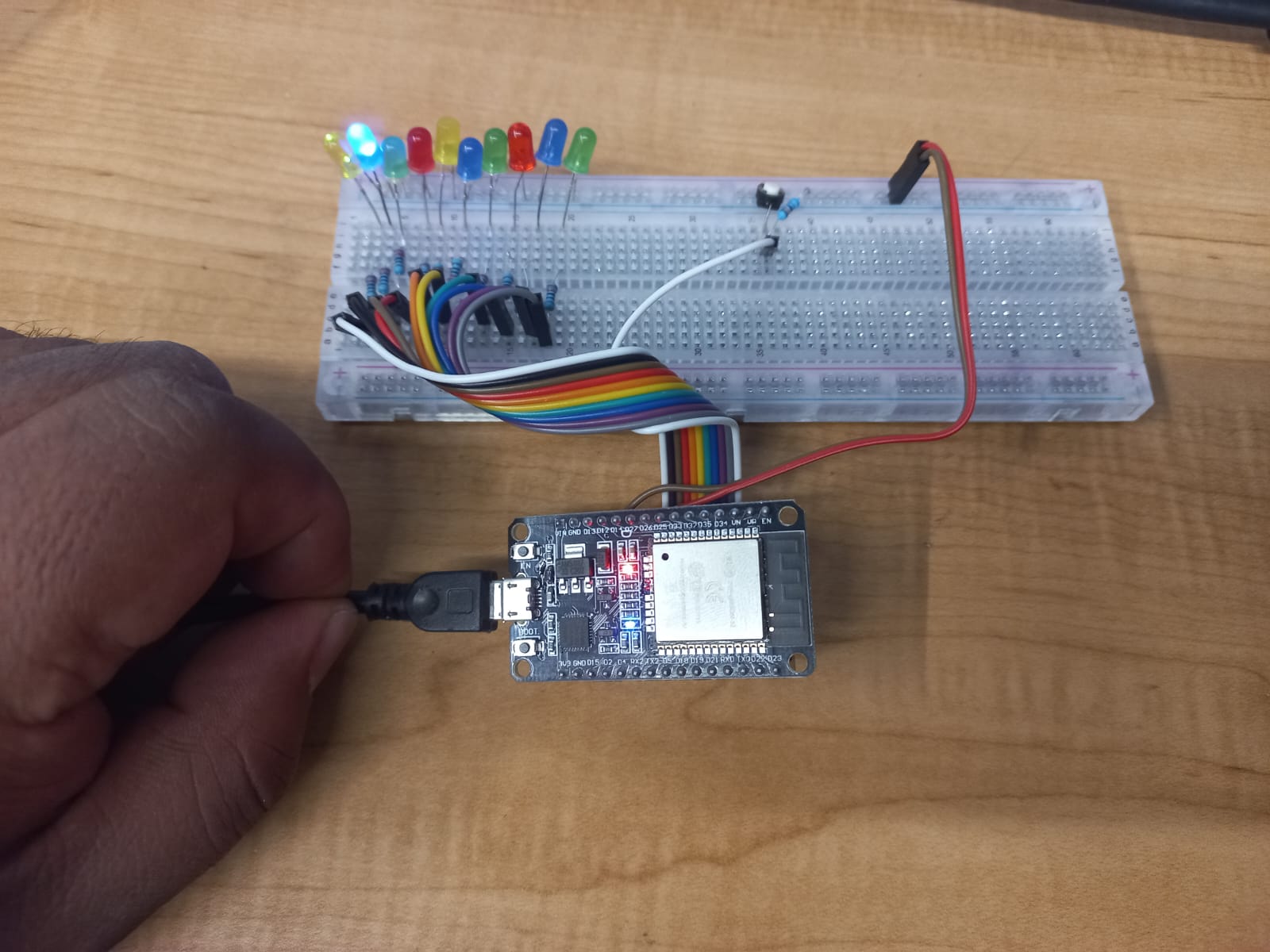
The following program blink 10 leds consecutive one after another in one direction, if we push the button the blinking direction change.
ESP32 code development
//ESP32 BLINKING LEDS
int LEDS[10]={15,2,16,17,5,18,19,21,22,23};
//pines of ESP32 used to blink LEDs.// the setup function runs once when you press reset or power the board
void setup() {
// initialize digital pin LED_BUILTIN as an output.
for(int i=0;i<10;i++)
{ pinMode(LEDS[i],OUTPUT);}
pinMode(34,INPUT);
}
// the loop function runs over and over again forever
void loop() {
if (digitalRead(34)==0)
{
for(int i=0;i<10;i++)
{digitalWrite(LEDS[i], HIGH); // turn the LED on (HIGH is the voltage level)
delay(10); // wait for a 0.05 second
digitalWrite(LEDS[i], LOW); // turn the LED off by making the voltage LOW
delay(10);} // wait for a 0.05 second
}
else
{
for(int i=9;i>=0;i--)
{digitalWrite(LEDS[i], HIGH); // turn the LED on (HIGH is the voltage level)
delay(10); // wait for a 0.01 second
digitalWrite(LEDS[i], LOW); // turn the LED off by making the voltage LOW
delay(10);} // wait for a 0.01 second
}
}
Video of ESP32 blinking LEDs
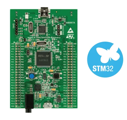
STM32F407 Discovery kit
The STM32F4DISCOVERY Discovery kit leverages the capabilities of the STM32F407 high-performance microcontrollers, to allow users to develop audio applications easily. It includes an ST-LINK/V2-A embedded debug tool, one ST-MEMS digital accelerometer, one digital microphone, one audio DAC with integrated class D speaker driver, LEDs, push-buttons, and a USB OTG Micro-AB connector.
STM32F407 ALL FEATURES
- STM32F407VGT6 microcontroller featuring 32-bit Arm® Cortex®-M4 with FPU core, 1-Mbyte Flash memory and 192-Kbyte RAM in an LQFP100 package
- USB OTG FS
- ST MEMS 3-axis accelerometer
- ST-MEMS audio sensor omni-directional digital microphone
- Audio DAC with integrated class D speaker driver
- User and reset push-buttons
- Eight LEDs: > LD1 (red/green) for USB communication > LD2 (red) for 3.3 V power on > Four user LEDs, LD3 (orange), LD4 (green), LD5 (red) and LD6 (blue) > Two USB OTG LEDs, LD7 (green) VBUS and LD8 (red) over-current
- Board connectors: > USB with Micro-AB > Stereo headphone output jack > 2.54 mm pitch extension header for all LQFP100 I/Os for quick connection to prototyping board and easy probing
- Flexible power-supply options: ST-LINK, USB VBUS, or external sources
- External application power supply: 3 V and 5 V
- Comprehensive free software including a variety of examples, part of STM32CubeF4 MCU Package, or STSW-STM32068 for using legacy standard libraries
- On-board ST-LINK/V2-A debugger/programmer with USB re-enumeration capability: mass storage, Virtual COM port, and debug port
- Support of a wide choice of Integrated Development Environments (IDEs) including IAR Embedded Workbench®, MDK-ARM, and STM32CubeIDE
STM32F407 Discovery kit Pinout
Programing the STM32F407 Discovery kit using ARDUINO IDE
We use the ARDUINO IDE due to it is easy to use and really intuitive.
The following program blink 10 leds consecutive one after another in one direction, if we push the button the blinking direction change.
STM32F407 DISCOVERY KIT code development
#include STM32Examples.h
//STM32F407 DISCOVERY KIT BLINKING LEDS
char LEDS[10]={PC7,PC9,PA9,PA13,PA15,PC11,PD0,PD2,PD4,PD6}; //pines of STM32F407 DISCOVERY KIT used to blink LEDs.
// the setup function runs once when you press reset or power the board
void setup() {
// initialize digital pin LED_BUILTIN as an output.
for(int i=0;i<10;i++)
{ pinMode(LEDS[i],OUTPUT);}
pinMode(PB7,INPUT);
}
// the loop function runs over and over again forever
void loop() {
if (digitalRead(PB7)==0)
{
for(int i=0;i<10;i++)
{digitalWrite(LEDS[i], HIGH); // turn the LED on (HIGH is the voltage level)
delay(10); // wait for a 0.05 second
digitalWrite(LEDS[i], LOW); // turn the LED off by making the voltage LOW
delay(10);} // wait for a 0.05 second
}
else
{
for(int i=9;i>=0;i--)
{digitalWrite(LEDS[i], HIGH); // turn the LED on (HIGH is the voltage level)
delay(10); // wait for a 0.01 second
digitalWrite(LEDS[i], LOW); // turn the LED off by making the voltage LOW
delay(10);} // wait for a 0.01 second
}
}