9. Output devices
Group assignment:
Individual assignment:
Add an output device to a microcontroller board you've designed and program it to do something.
Go to:
Group work
In group work we were to measure the power consumption of an output device. We documented our results to the group work page which is on our Fablab Oulu pages. Check out our results!
Reflection
This week in group work we decided to use an OLED and an LCD screen. I will use one in my final project, so I already had decided to test one this week. Read further down on how I started working with it!
In the group work we tested for the display power draw for the OLED and the LCD screen first without any action, then with writing text and also the LCD with display backlight off.
So first the multimeter was connected between power and the display. Oled was using 0.014W and LCD 0.05W, so a small difference there.
When we got some text in LCD display, the reading we got (backlight on) was 0.29 W. As with the power draw of 0.04 W with the backlight off, we saw that the backlight is the source taking most of the power. When we measured the overall consumption for the screen with the backlight on, we got the highest reading of 0.51 W.
The OLED is said to have very low power consumption with high efficiency. LCDs require backlight whereas OLEDs emit the light themselves with pixels, this particular one in 128 x 64 pixels. In LCD even a small LED backlight drawing tens of mA can easily overshadow the rest of the power consumed in the display. There is of course a size difference also in these displays we used.
Output device
Setting up
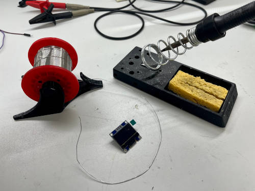
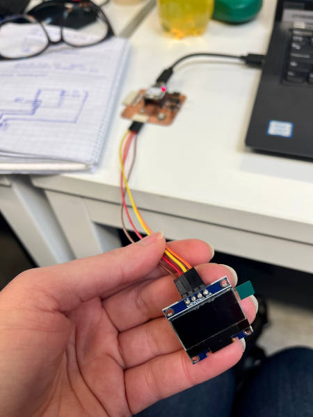
I had an OLED screen with me, and at first I went and soldered the pins into it. I attached it to a breadboard to secure a good leveling and soldered. It went easier than the previous time, and I didn't even have my glasses on!
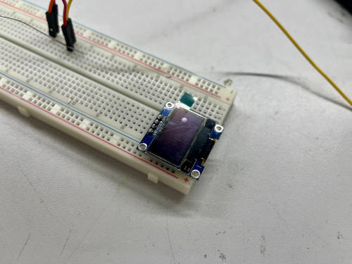
Then I checked what are the pins the OLED is using. They were: VCL, SDA, Ground and Power 3,3V. These are marked on the OLED.
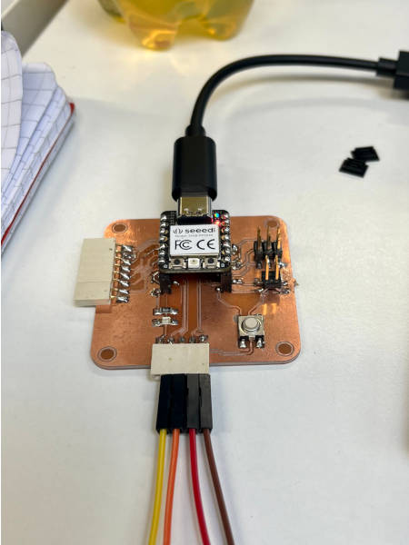
With the OLED I used my previously designed and produced development board. It was designed in Week 6. and made in Week 8.
From these weeks and also the Embedded programming week I knew where the pins were on the microcontroller RP2040. I just had to attach them my OLED accordingly. It didn't fit straight to the pin connectors, so I used jump wires.
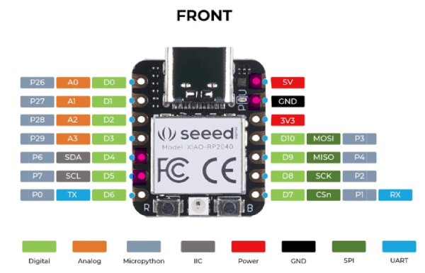
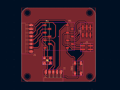
As seen in the design, the SCL, SDA, Power and Ground were routed to the 5-head pin connector in the board. That is where I connected my jump wires accordingly.
Arduino
Before I was able to test if this works, I had to download some libraries to Arduino. I had earlier watched some examples from Random nerd tutorials and spotted some libraries from there. I also used the Fab Academy page of Adrian Torres to learn and find code.
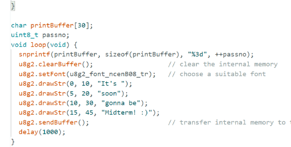
To write to display I needed Adafruit_SSD1306 and a graphics library called u8g2. After downloading them, I connected my board to my computer, and tried to run a couple of codes that write to the display. One of them was the code Adrian had modified, so I knew it should be working. But nothing was happening.
At this point I downloaded another library for using the LCD screen called LiquidCrystal_PCF8574.h. I attached the LCD display my instructor had tested, run the code that was known to work, and still nothing happened. Now I knew the problem had to be in my board.
I put on my glasses and looked at my board. I saw something there, and went downstairs to look with a microscope. There were a couple of places that had really much soldering tin in them. I asked one of my instructors to give me an opinion, and he said right away there is a short circuit. He helped me to take off the excess tin.
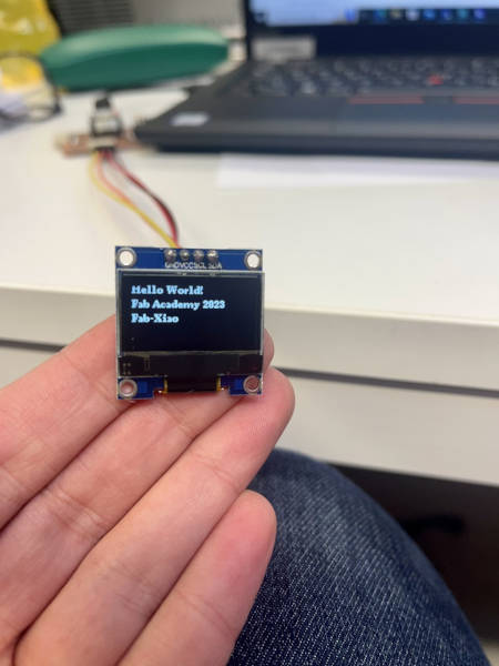
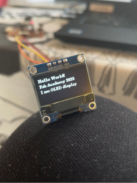
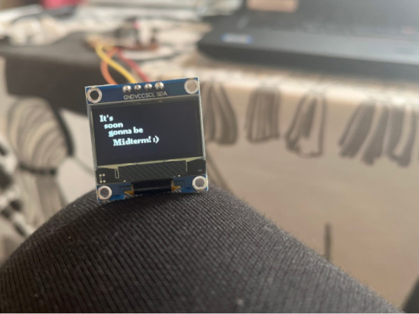
Back to the computer. I connected my board, and run the code Arduino Hello_OLED that Adrian had used. And it worked!! I was so happy.
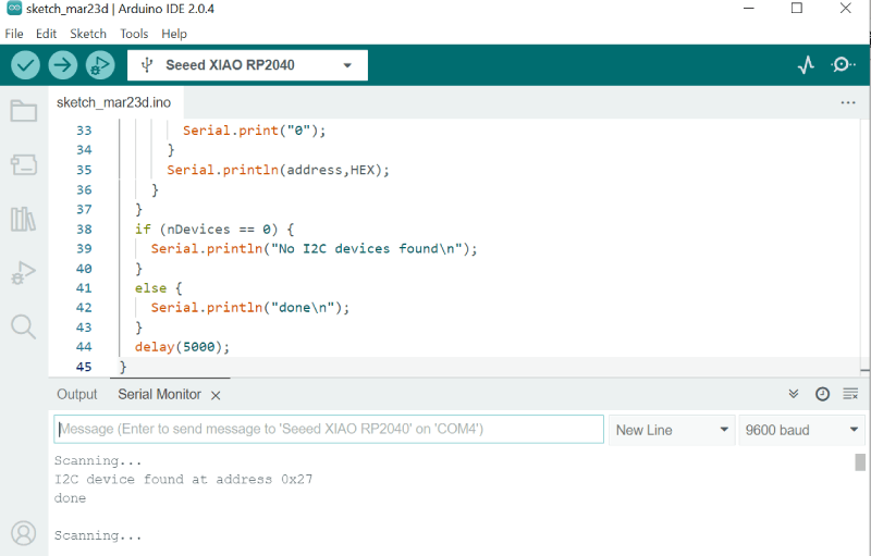
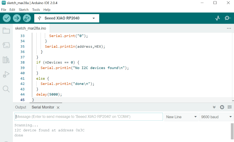
I wanted to also learn how to find out the device adress if I needed it sometime. The code for that I found from the above mentioned Random Nerd Tutorial by Rui Santos and it is here.
I ran the code for both OLED and the LCD, and opened serial monitor for the results. It was 0x27 to LCD and 0x3 to OLED.
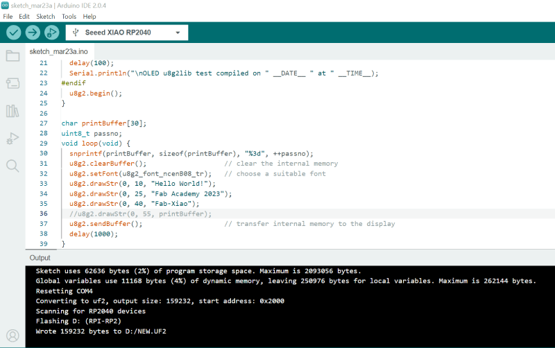
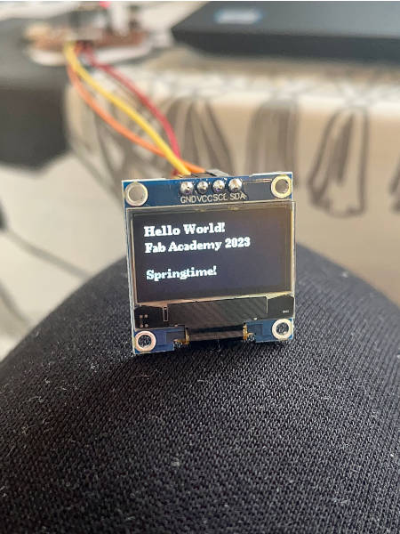
I wanted to do some small testing now that I got started. First I changed the message in Adrians' code.
Then I wanted to change the cursor place vertically for the last word.
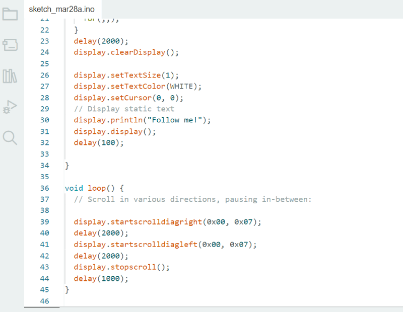
In the OLED tutorial I already mentioned here, I also saw a sample of how to scroll text. I took the example code from there and modified it. I wanted my word to say 'Follow me' and scroll diagonally from left to right and back again and then stop for a while.