4. Embedded programmig
This weeks assignment was to start learning about embedded programming.
In group assignment we were to compare the performance and development workflows for other architectures.
We documented our work to the group work page which is on our Fablab Oulu pages. Check out how we did the tests!
I learned how to install board manager for the boards and how to define board information.We looked up from the given code what pins we needed to use. From the oscillator we got the measured frequencies.
Three microchip developer boards were tested. The test measures showed how quickly general purpose input/output (GPIO) pins can communicate with a processor core. From Ring oscillator timing test table here: Two pins are connected; a bit is output on one, read on the other, inverted in software, and the loop repeated, with the frequency of the resulting oscillation reported. Twice this frequency is the rate of reading, modifying, and writing to pins.
RP2040 was a clear winner with 9.47 MHz output frequency. ESP32C3 was the second with 3.808 MHz frequency. SAMD21 was last, with 1.54 MHz output frequency.
Individual assignments were:Go to:
- Learning the datasheet
- Setup for programming
- Programming
Learning the datasheet
We started our local lecture with learning about setup. We were given two boards:
The microcontrollers are a new topic to me so I will try my best to learn the essentials. I will use the RP2040 here as an example. Also on our global lectures I got the idea that RP2040 could be the one I will be using in my final project so I think it is crucial to get to know it, and go through it's datasheet.
RP2040 is a microcontroller from Rasberry Pi.
Overview on Seeed wiki here: There are 14 GPIO PINs on Seeed Studio XIAO RP2040, on which there are 11 digital pins, 4 analog pins, 11 PWM Pins,1 I2C interface, 1 UART interface, 1 SPI interface, 1 SWD Bonding pad interface.
From these pictures below, I tried to understand what is going on. The simpler pictures are quite clear, but the datasheets pinout is more complex.
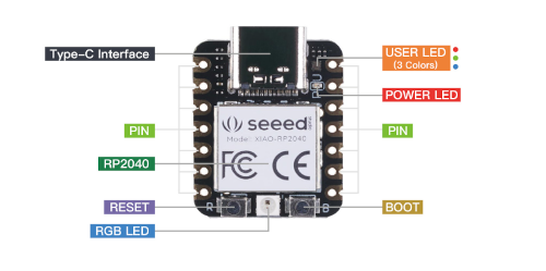
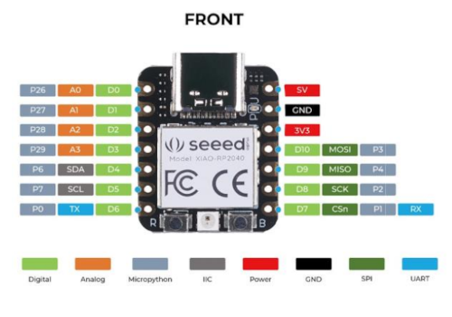

So there are 14 general-purpose input/output pins for users, some of them digital some of them analog and so fort.
There is a reset and a boot button. It also has a red power LED & an on-board RGB LED.
In datasheet factory test mode pin in marked Testen.
A Neopixel LED is also available on the Board which can be programmed. The Board has a type C USB interface for programming and Serial Communication.
There are many pins marked for different power supplies in datasheet. From them I looked up:
IOVDD: for general I/O pins. Working voltage of MCU is 3.3V. Voltage input connected to general I/O pins may cause chip damage if it's higher than 3.3V.
ADC_AVDD: for power supply pins. The built-in DC-DC converter circuit is able to change 5V voltage into 3.3V and allows to power the device with a 5V supply via VIN-PIN and 5V-PIN.
In datasheet the functions of each individual GPIO is described thoroughly.
I also found some safety instructions from datasheet:
The datasheet seemed to be filled with information my own processor (brain) could not read or process. But one part that got my attention was the section about memory. RP2040 has embedded ROM and SRAM, and access to external Flash via a QSPI interface.
ROM: It contains: Initial startup routine, Flash boot sequence, Flash programming routines, USB mass storage device with UF2 support and Utility libraries such as fast floating point.
SRAM: There is a total of 264kB of on-chip SRAM. Physically this is partitioned into six banks, as this vastly improves memory
bandwidth for multiple masters, but software may treat it as a single 264kB memory region.
Flash: External Flash is accessed via the QSPI interface using the execute-in-place (XIP) hardware. This allows an external flash memory to be addressed and accessed by the system as though it were internal memory.
One interesting section was also power control, since it is advertized that the board has low-power modes to support extended-duration operation on battery power. For example options for reducing dynamic power are top-level clock gating of individual peripherals and functional blocks, and automatic control of top-level clock gates based on processor sleep state, dormant state, and these are carefully described in datasheet.
The next thing that caught my eye was the chapter about GPIOs. RP2040 has 36 multi-functional General Purpose Input / Output (GPIO) pins, divided into two banks. In a typical use case, the pins in the QSPI bank are used to execute code from an external flash device, leaving the User bank (GPIO0 to GPIO29) for the programmer to use.
All GPIOs support digital input and output, but GPIO26 to GPIO29 can also be used as inputs to the chip’s Analogue to Digital Converter (ADC). Each GPIO can be controlled directly by software running on the processors, or by a number of other functional blocks.
One chapter I also checked up was Peripherals. It contains loads of information for example on USB, UART, I2C ( 2-wire interface that can be used to connect devices for low speed data transfer), PWM (pulse width modulation is a scheme where a digital signal provides a smoothly varying average voltage), Timer (provides a global microsecond timebase for the system), ADC ( internal analogue-digital converter) and temperature sensor.
Browsing through the datasheet most definitely gave me a headache just by it's magnitude. But it is obvious that some of the information will be needed, and now I might know a bit better from where to start searching.
I've heard the saying that a wise man knows that he knows nothing. Well, I most certainly am quite wise then.
Setup for programming
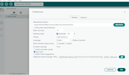
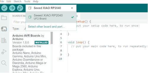
This is the setup for RP2040. I started the installation in Arduino IDE. I opened File -> Preferences and added additional board manager URL which we were given.
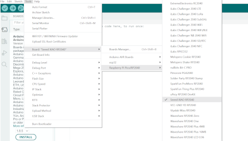
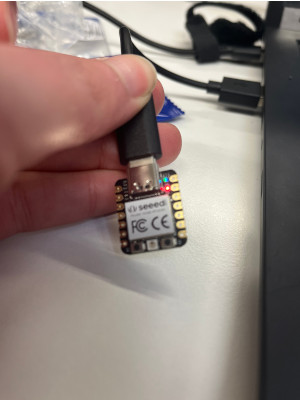
Then I went to Tools -> Boards manager, wrote RP2040 and installed platform Rasberry Pi Pico RP2040. After that I could select the board XIAO RP2040. At his point I finally got to take the board out and attach it to my computer with the USB cable. From Tools -> Port we were supposed to find the port, but at first there was nothing to be found. So I had to hold down the Boot -button (down on the right) for the board, and then press the Reset button (on the down left). There were tiny letters beside these buttons on the board telling me which was which. I had to do it twice but finally it was recognized and I could now choose from Tools -> Port -> UF2 board.
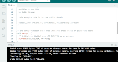
Now that everything was working, I tested the system from Open file -> Examples -> Basic -> Blink. So the code opened, and tried the Verify. Everything was alright, no red lines, so I went forward and uploaded the code to the chip. Now the chip started blinking as it was told to do in the code! The built-in LED started blinking, and it turns on the LED for one second and then off for one second and repeats that. Success. I felt like Alice in Wonderland.
Programming
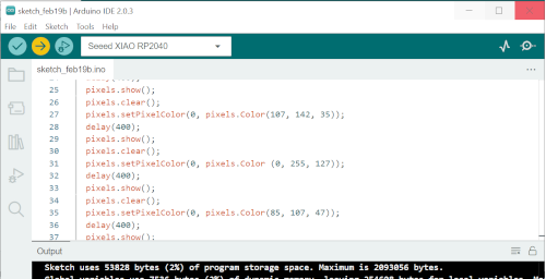
The next step was to try and understand a code. I chose an example code from how2electonics found here. It blinks the user programmable RGB LED on board. In the code there are 5 different colors assigned (in original code rainbow colors) with led.pixels_fill((x,x,x)). I chose only to change these colors. I looked up some RGB values for different green colors, and replaced the existing ones with those. It worked well. Before that for some reason Arduino seemed to loose the board a few times, so I had to press the reboot and reset button a few times.

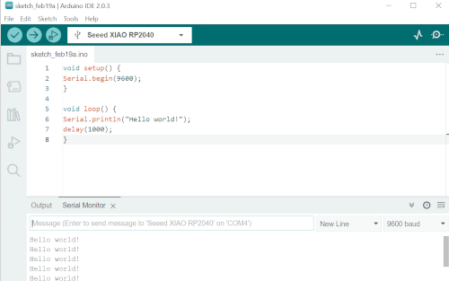
After that I chose to try sending a message, the famous hello world code. I checked if it works, and of course it did. For to see it work, I opened the serial monitor from tools. It is a integrated monitor that opens up where the console log is located as a tab.
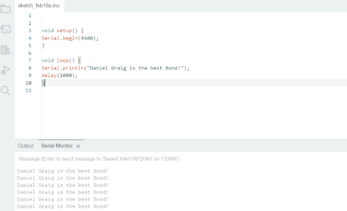
To annoy one of my friends, I changed the message a bit.
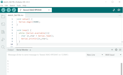
I wondered if I could make the letters of a word be spread as invidual characters. I found out from Arduino.cc that serial.read reads incoming data. The while serial.available waits for serial input, and then it is just printed on a line. I had to try a few times before my code was right but I got there.
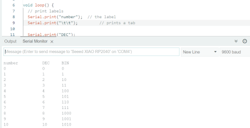
Then I read some guides about presenting ASCII code in different ways. I got interested in presenting something in a table. I found a code about a table from Arduino.cc. It makes columns, and prints out numbers from 0 to 63 in decimal, hexadecimal, octal and binary. With tabs it makes the spaces needed. I chose to change it a bit. I wanted to put in numbers between 1-10 (and name the columns as numbers), and I only wanted them to be presented in decimal and binary. As I went through the code, I typed in reminders to myself what everything is doing.
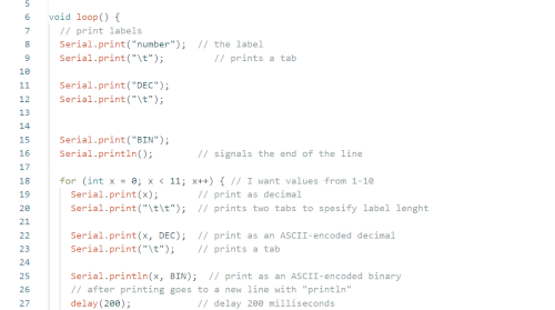
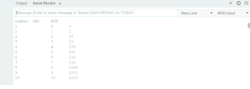
At this point I noticed the columns names were not in the right place, so I added one tab with \t. Now it was good!
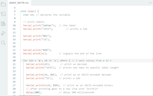
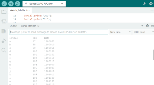
Then I figured out I want to try letters instead. I googled and found out ch was the right choice, so I defined ch = from a to z.
So I tried these minor changes and variations to get more comfortable with code and Arduino IDE, and even though this is just a beginning, I'm happy. There's a lot to learn, but at least I know now how and where to start.
Here are the mentioned codes I used, in text files. I have problems getting .ino files here. I finally got the code/sketches saved as .ino, after opening the Arduino IDE with admin rights, but now I cannot see those files in my personal disk spaces.