This week's fun assignment was:
Group assignment:- Characterize the design rules for your in-house PCB production process: document feeds, speeds, plunge rate, depth of cut (traces and outline) and tooling.
- Document your work to the group work page and reflect on your individual page what you learned
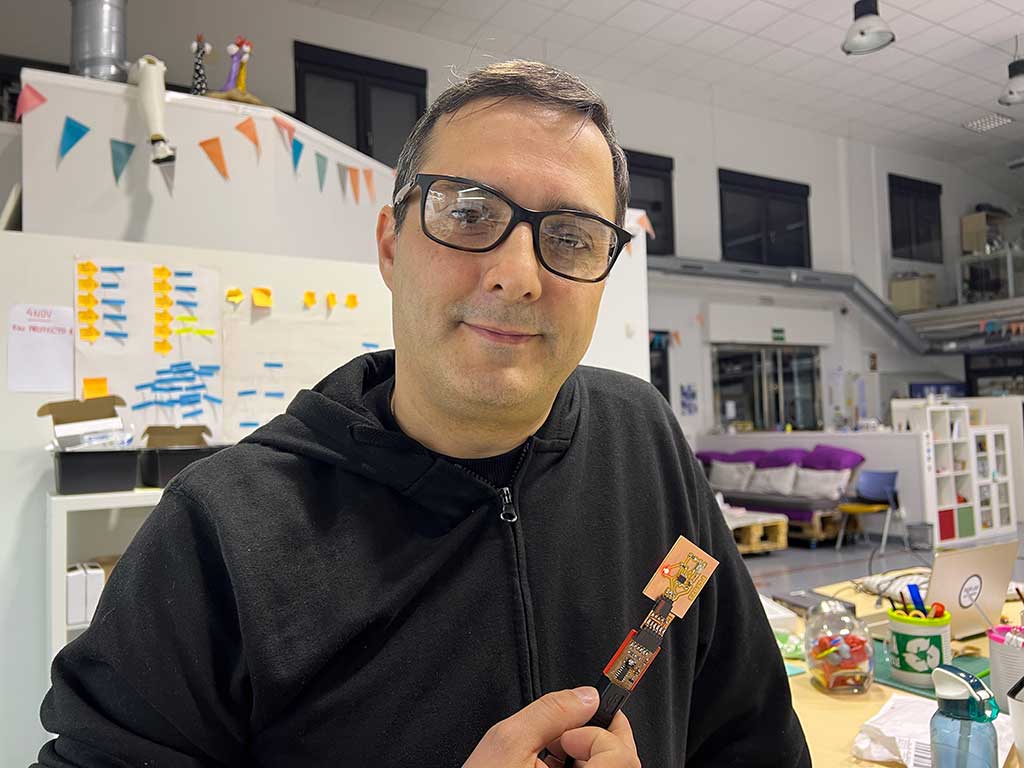
- Make and test the development board that you designed to interact and communicate with an embedded microcontroller

Electronics production
What I did this week
Also made this:
Group assignment
- Characterize the design rules for your in-house PCB production process: document feeds, speeds, plunge rate, depth of cut (traces and outline) and tooling.
- Document your work to the group work page and reflect on your individual page what you learned
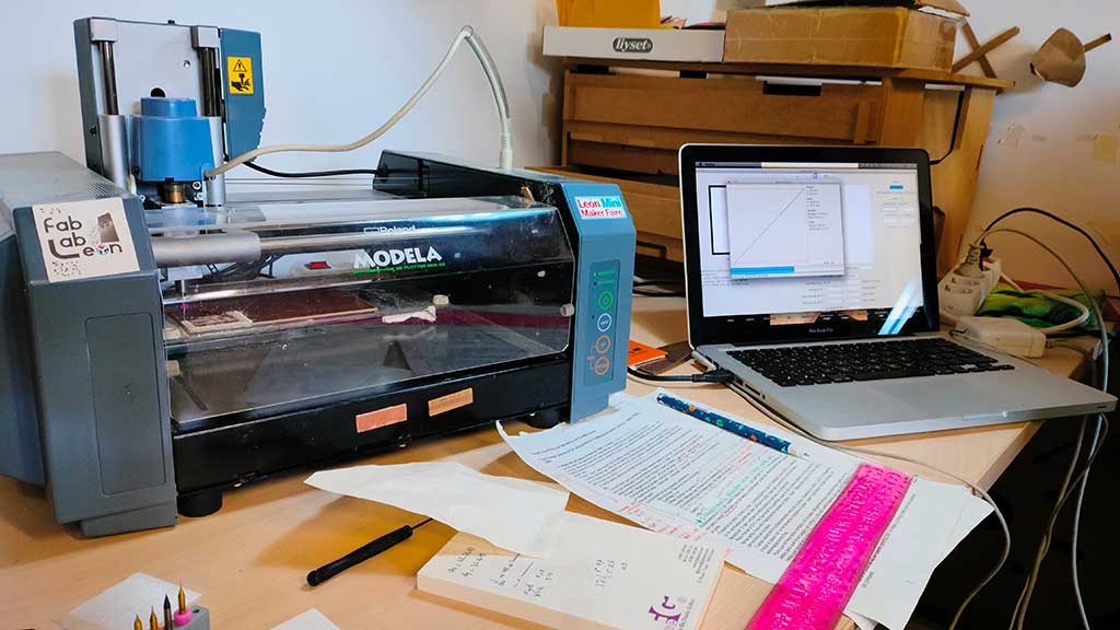
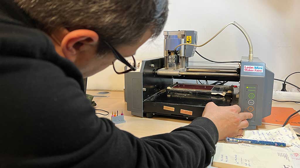
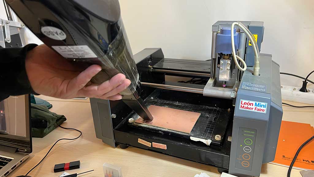
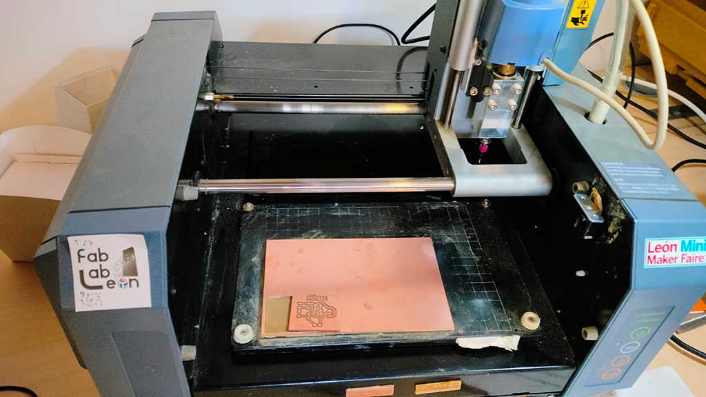
For this week's assignment I will be using Fab Lab León's Roland MDX-20A Modela
Specifications
| XY table size | 220 (X) x 160 (Y) mm |
| Max. operation area | 203.2 (X) x 152.4 (Y) x 60.5 (Z) mm |
| Max. table load weight | 1000 g |
| Interface | Serial (RS-232C) |
| Control keys | STANDBY key, VIEW key, TOOL-UP key, TOOL-DOWN key |
| Acoustic noise level | Standby mode: under 35 dB (A) Operation mode (not cutting): under 70 dB (A) (According to ISO 7779) |
| External dimensions | 476.8 (W) x 381.6 (D) x 305 (H) mm | Weight | 13.7 kg (30.2 lb.) |
| Operation temperature | 5 to 40°C |
| Tool chuck | 6 mm or 1/8 in. tool chuck included |
| Spindle motor | 10W (DC motor) |
| Software resolution | 0.025 mm/step (0.000984 in./step) |
| Mechanical resolution | 0.00625 mm/step (0.000246 in./step) |
| Revolution speed | 6,500 rpm |
| Feed rate | 0.1 to 15 mm/sec. (0.00393 to 9/16 in./sec.) |
| Acceptable material | Wood, Plaster, Resin (modeling wax, styrenform), Chemical wood |
| Acceptable tool | Endmill, Drill |
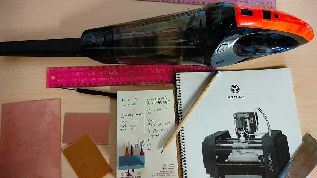
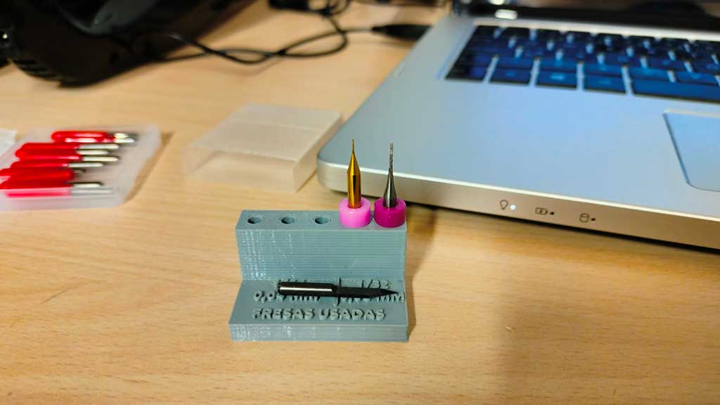
And for milling, I will be using the following tools:
- Tools: Milling bit 0,4 mm (1/64”); Milling bit 0,8 mm (1/32”);
- Material: FR-1 Printed Circuit Board 75 x 50 mm.;
- Software: Mods / Mods CE;
- A Flexible ruler;
- A Notebook and a pen or pencil;
- A vacuum cleaner;
- The manual;
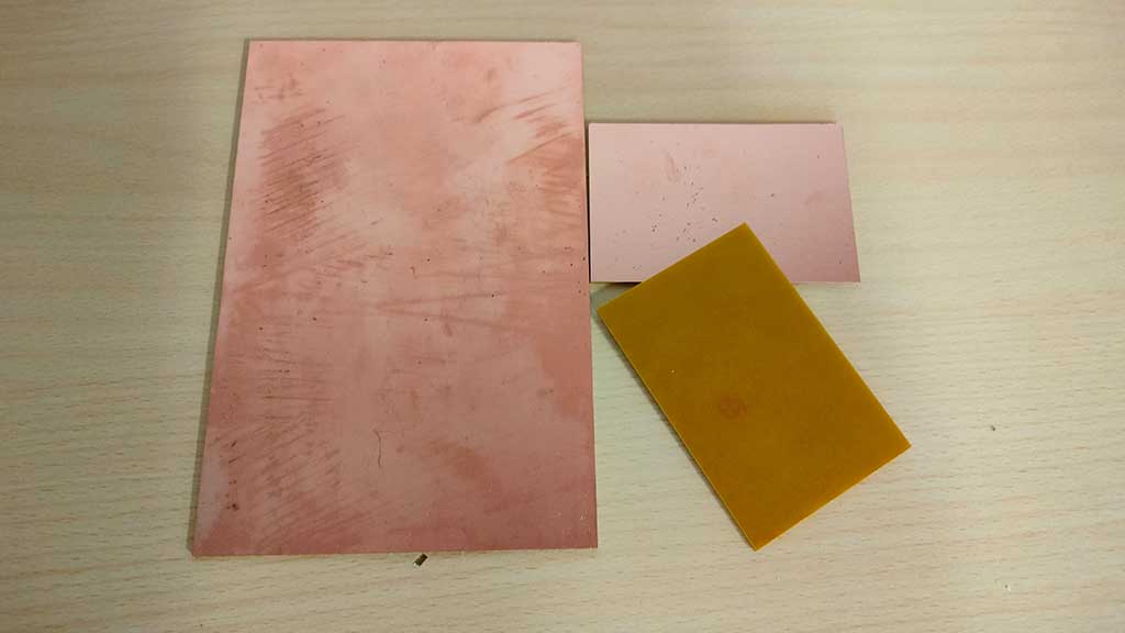
Fab Lab León has different boards to engrave. From one side boards to two side boards, with different sizes:
But first, the safety training:
Safety norms and procedures:
- The equipment must be operated by one person at a time.
- Do not disconnect the cable by pulling on it or handle it with wet hands.
- Hair should be tied back and no loose objects (such as necklaces, scarves or bracelets) should be worn as they can get caught in the spindle.
- If necessary wear safety glasses. There is no need for any other protective clothing.
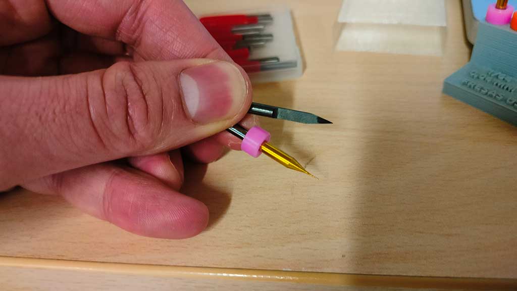
- DO NOT touch the tip of the end mill/end bit.
- DO NOT use your hands close to the end mill or probe during cutting or scanning
- While the machine is ON, DO NOT remove the rotor unit from the carriage.
- Do not forget to attach the housing when the machine is in operation.
- When finished, wash hands to remove shavings.
- In case of machine malfunction or emergency, switch off the machine and notify the fab lab manager;
- DO NOT use the machine if you notice an abnormal condition (burning smell, abnormal noise or similar, if it gives off smoke).
- Repair and maintenance work must be carried out under the supervision of the FAB LAB manager and following the instructions in the equipment manual.
- DO NOT allow metals or liquids to come into contact with the internal parts of the system.
- DO NOT insert METALLIC or FLAMMABLE OBJECTS into the equipment. They may cause a fire.
- Use a brush to clean metal shavings. Attempting to use a vacuum cleaner to remove metal shavings may cause a fire in the vacuum.
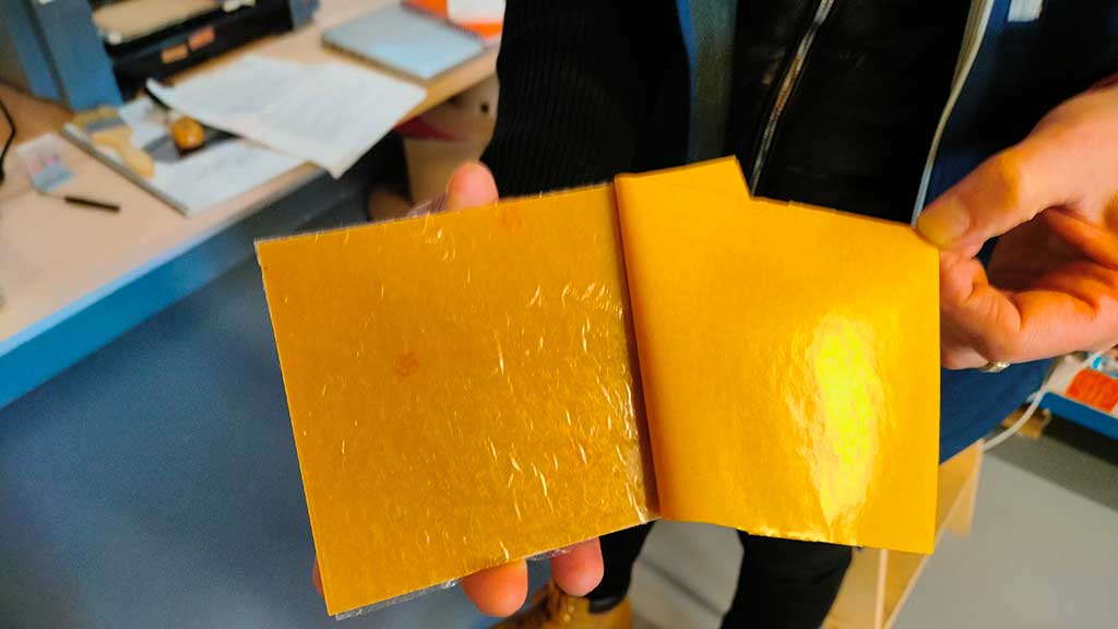
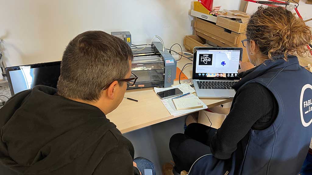
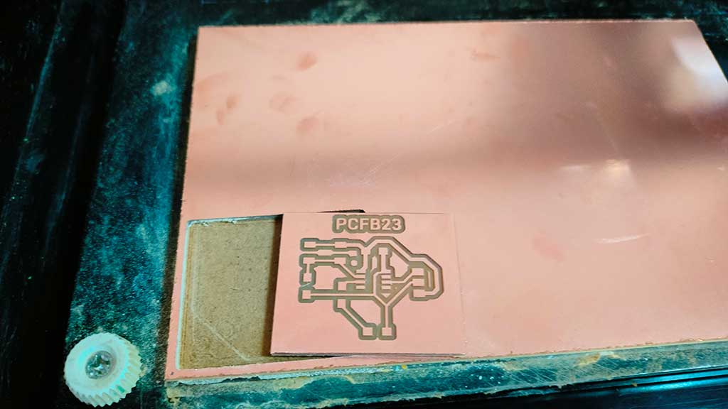
So to start Nuria explains that the way to fix the board for engraving is by using two side adhesive tape.
The tape is placed on one side of the board and glued to the sacrificial board that sits underneath.
The tape is cutted to the exact size of the board.
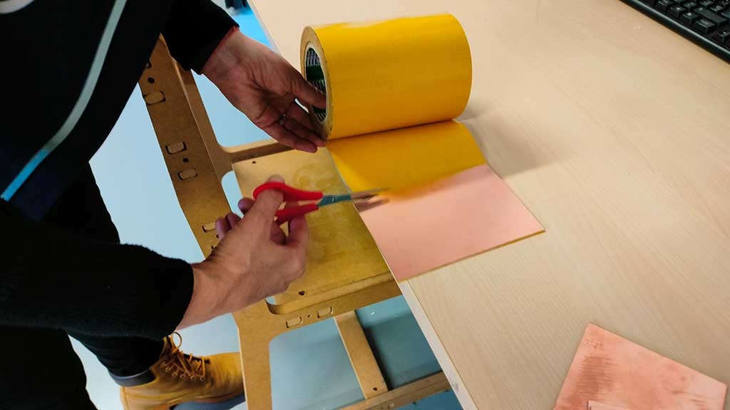
The board should be well glued down so as not to move.
Next we start preparing the machine for milling.
In Fab Lab León we only use FR-1 boards. That's because they are more safe to use.
We will do traces first so the end mill will be a 1/64", that is 0.4mm
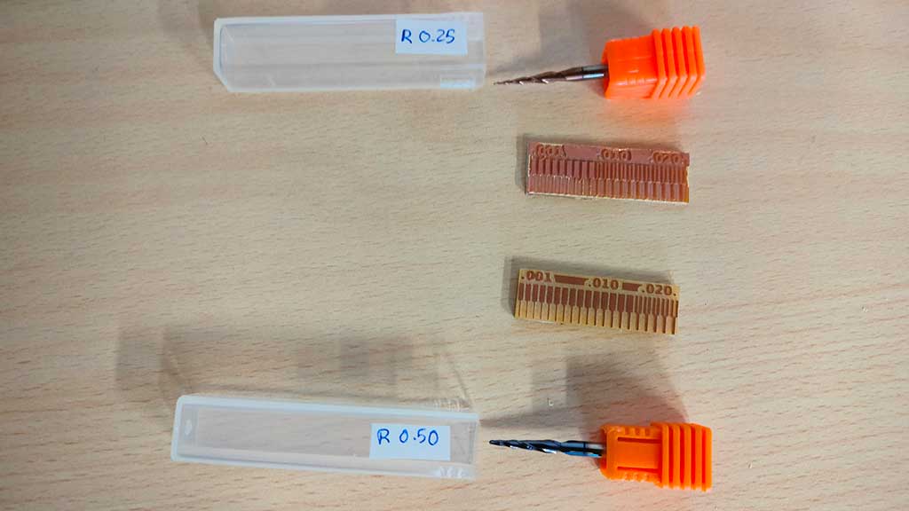
Tests with end mills
This part should be done where we want to "zero the machine".
To mount the end mills we must first push the up button until the milling head reaches a height that's comfortable to work.
Take note of the coordinates as we will need them on the board cutting part of the process.
We insert the end mill in the collet and fix a screw until the end mill is secure but not too tight. The End mill should also not be totally inserted.
Now we will push the down button making the carriage descend until there are just 2,3 mm until the board.
This is a more tricky part. We must secure the end mill with two fingers while slowly unscrewing just one of the screws to free an end mill.
Once it's free, we must slowly and carefully allow it to touch the material and fix its position by screwing again, this time, both screws.
I will add pictures of the process later.
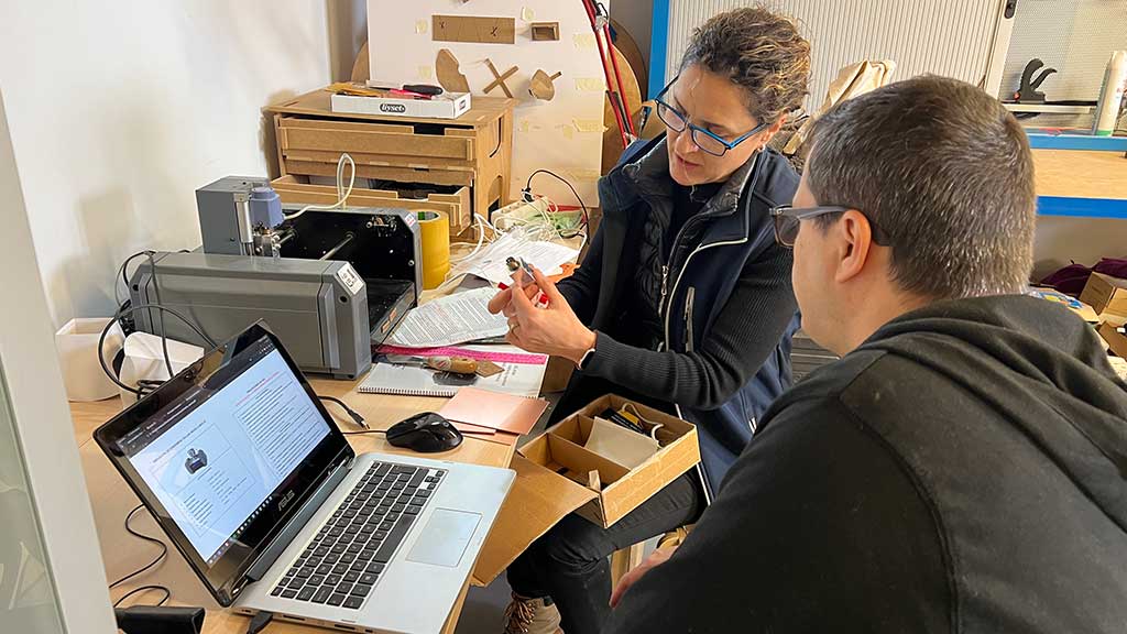
Before we start milling, Nuria inspects once again my board:
Now the software process for milling and cutting the board:
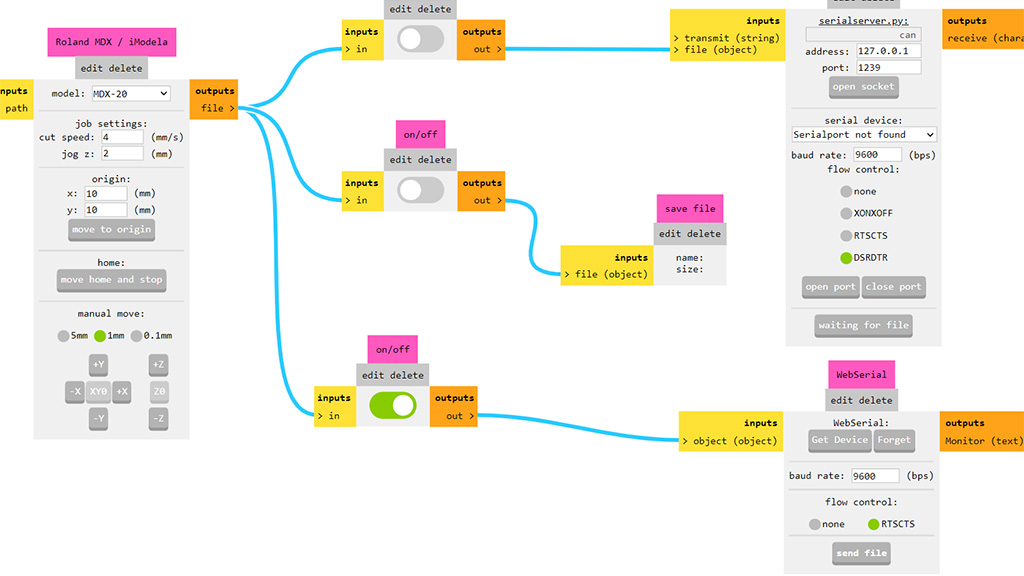
For the software We are going to use Mods:
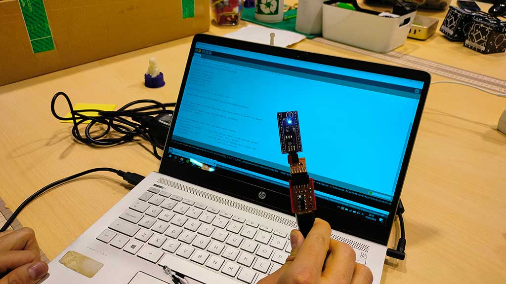
I started by locally installing it.
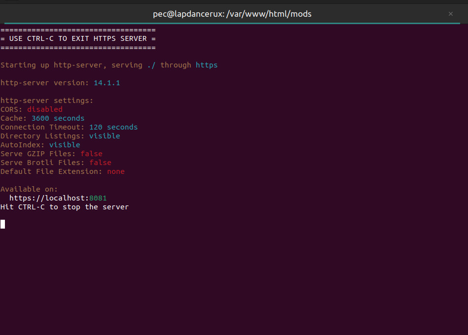
Although I followed the instructions on the GitHub page, I did have some trouble getting it to run.
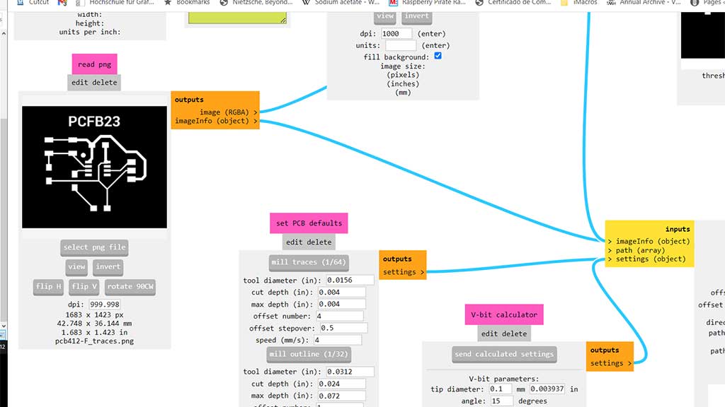
We must first put down on a paper the size of our board. This is important to check that the cutting file is the same size.
In the following image we can see the size of our board is going to be 42.748mmx36.144mm
Next we click in mill traces 1/64 and adjust the speed to 2.
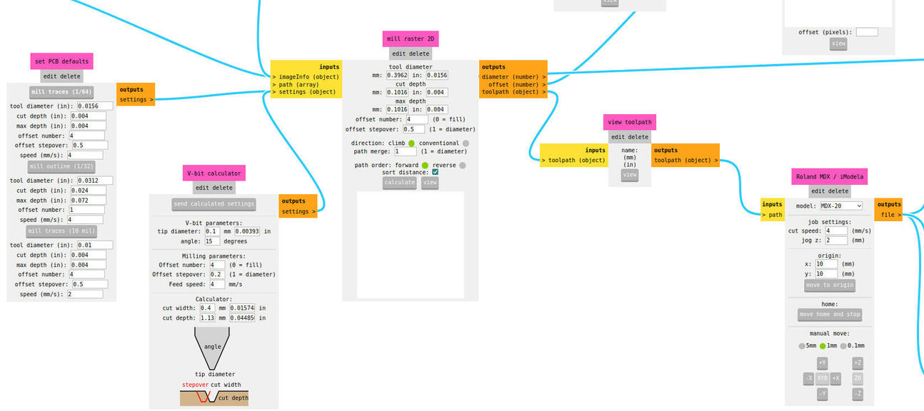
In Mill raster 2D we click calculate and everything seems ok, so we click on "view toolpath" to see the toolpaths:
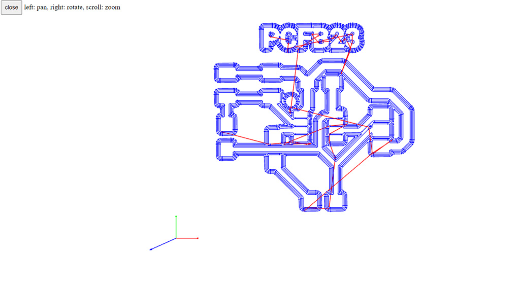
Summing up the important settings:
- Diameter = 0.4;
- Offset (number of traces) = 4;
- Overlap (between two traces for the selected bit) = 0.5;
- 2D Threshold (how it makes gray into black or white) = 0.5;
- Speed = 2;
- Z=-0.1;
- Jog=1.0;
Last steps, select the machine, the speed and jog, the origin, etc.
Our connection will be done via WebSerial.
Well...this didn't really work out as the machine doesn't complete the job. I ended up using an old version of Mods installed on an old computer.
At a later date and with the support of the Fab Lab León instructors, it was already possible to use Mods to make a board.
The process is the same as the one described above.
Individual assignment
- Make and test the development board that you designed to interact and communicate with an embedded microcontroller
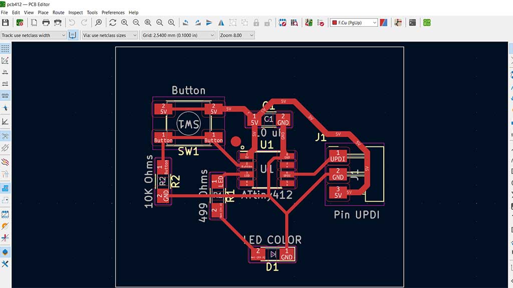
Before we start the milling process, this is what I'm going to make:
ATtiny412 board with a led, button, a couple of resistors and a capacitor:
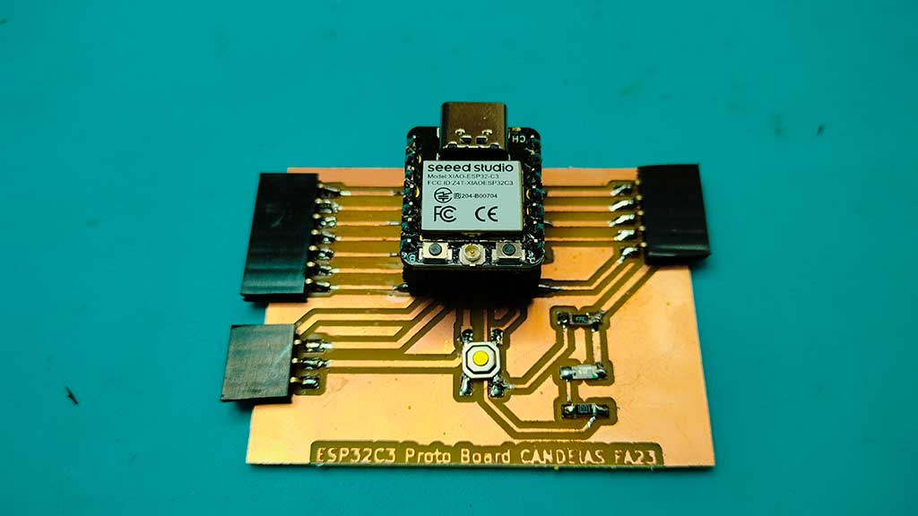
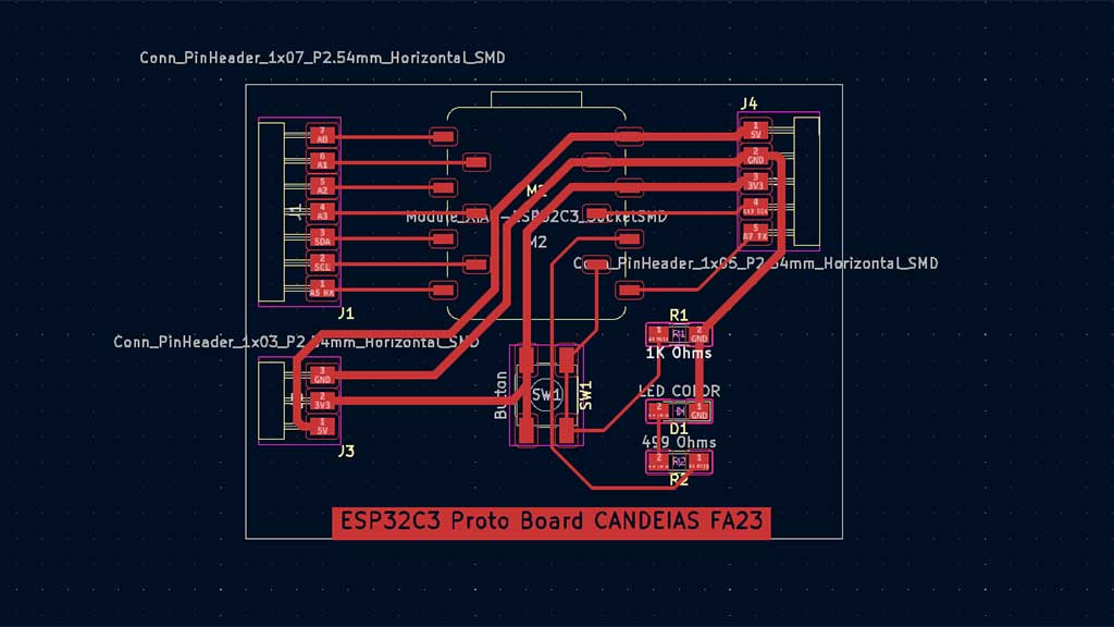
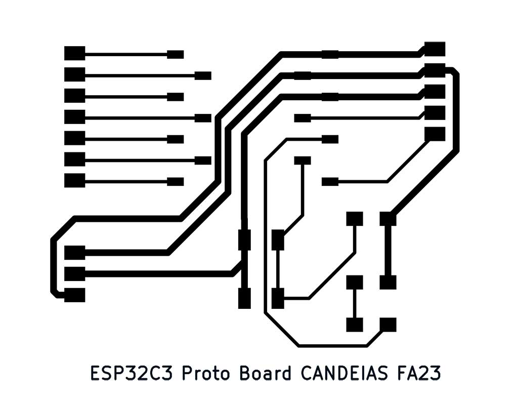
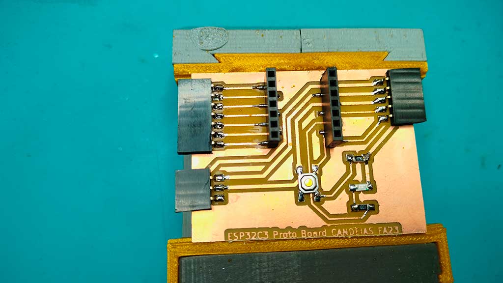
A shield to swap between XIAO's:
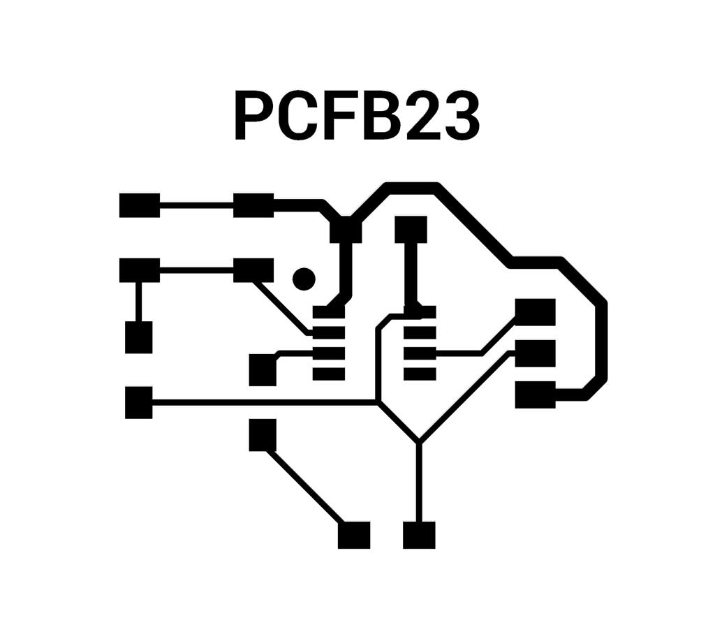
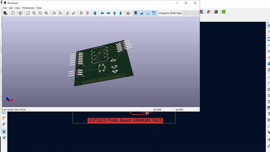
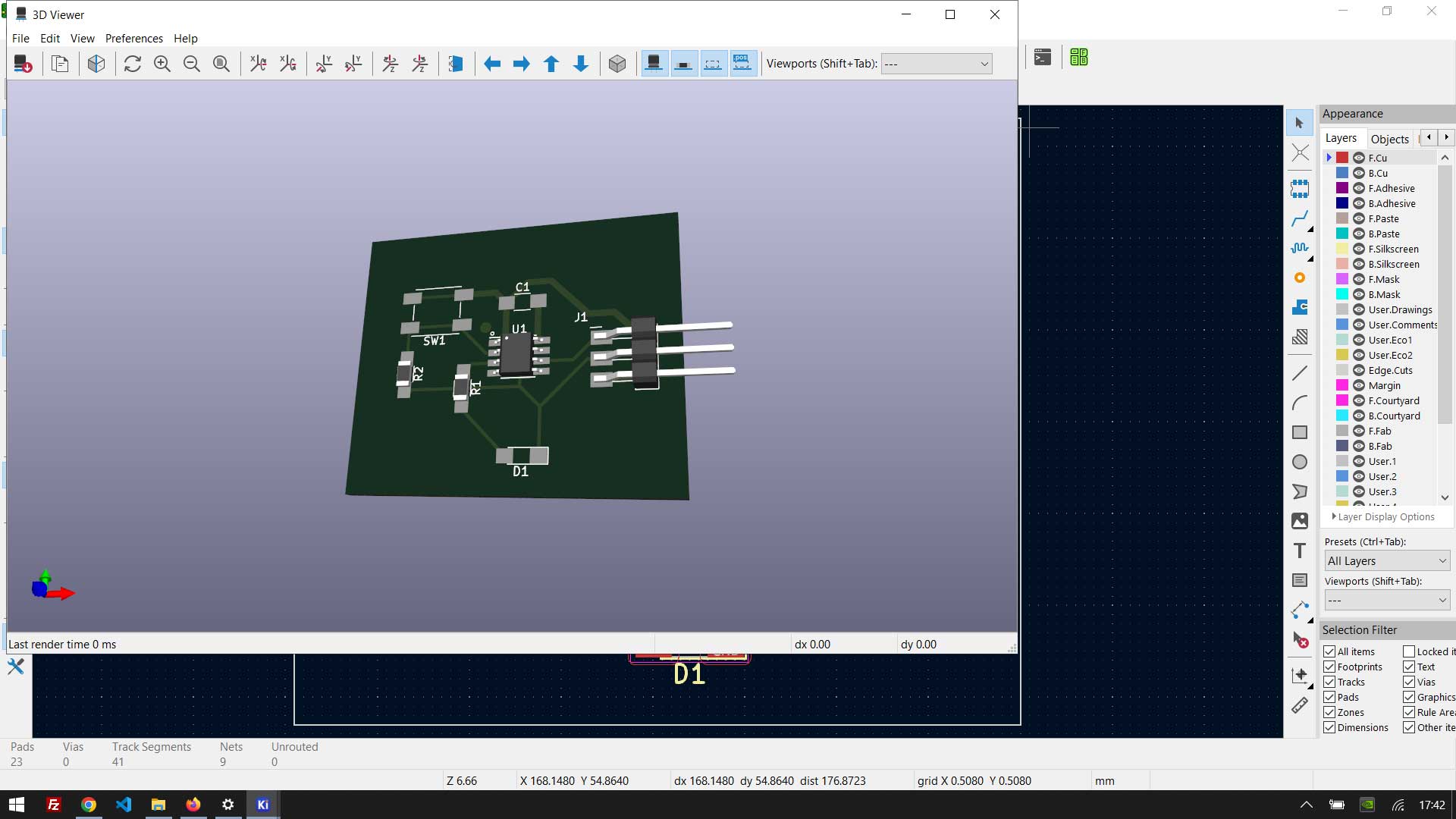
And hopefully they will look something like this:
After milling each board I will instruct the machine to cut the "edge cut"

And so...we start milling:
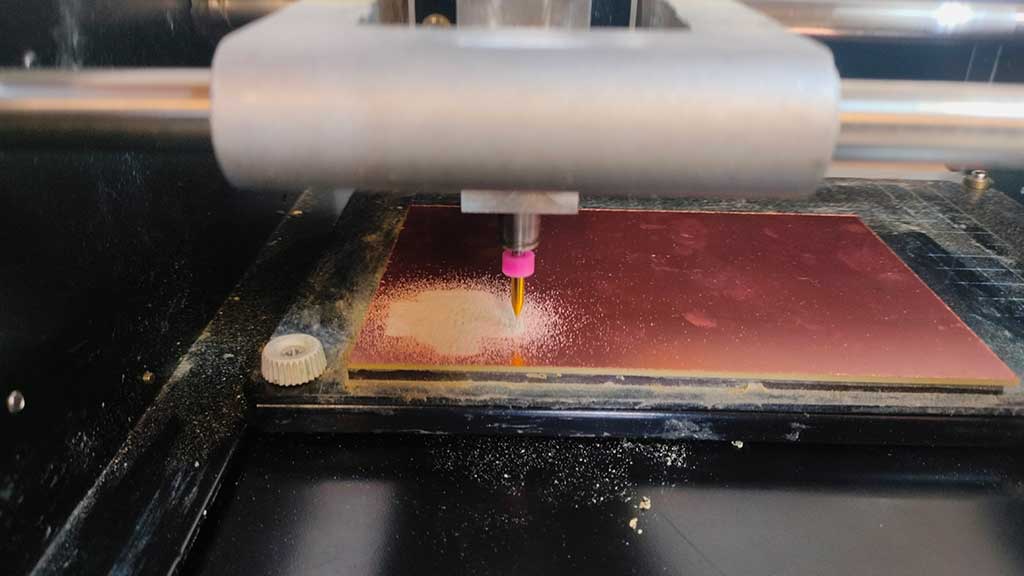
The milling process creates a very fine dust.
The best way to clean it is by vacuuming.
This can also be done while the machine is milling but it has to be done very carefully.
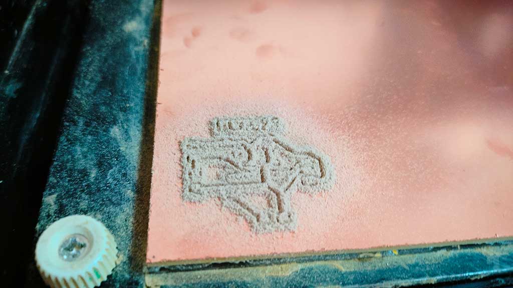
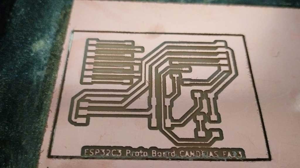
There we have it, the engraved and cutted PCB almost ready for assembly.
I repeated the process to make the second board:
After milling the boards should be washed and lightly scraped with a soapy steel wool sponge
A small iron ruler can also be used to clean the surface. The aim is to avoid bits of copper which could cause a short circuit.
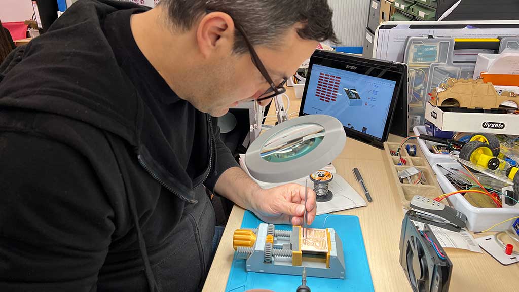
Now in order to assemble the boards we need to solder and that is something I don't have a lot of practice with.
I will solder with solder paste and a hot plate, and this is just a learning experience as the board was designed by Adrián Torres.
The way it works is like this:
First we collect all the components we need for the board:
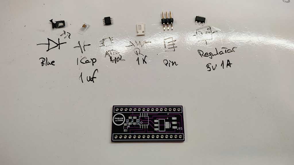
Fab Lab León has a lot of components in little boxes:
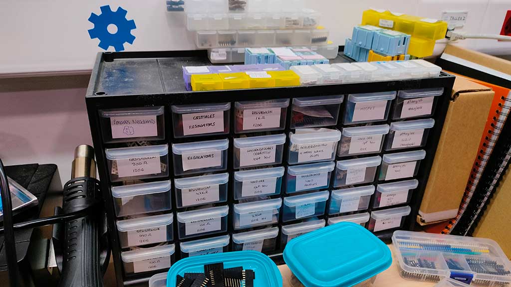
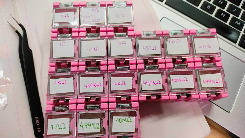
This part of collecting components is not specific to hot plate soldering. It's something that needs to be done every time we are preparing to solder components to a PCB.
When we have all our components we place some solder paste on a tile.
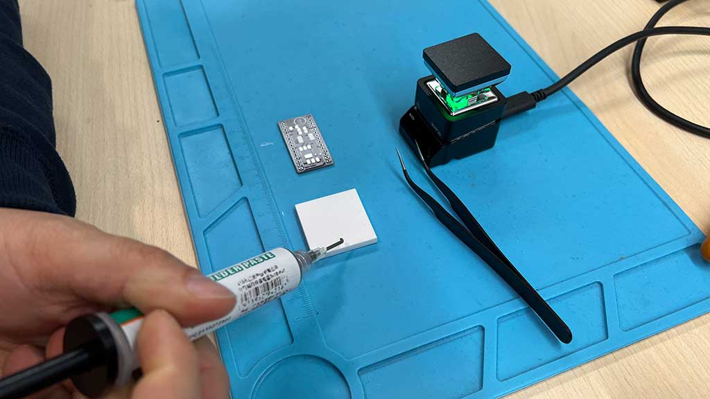
We can now start putting solder paste over the terminals:
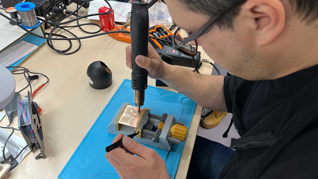
Now we need to heat the hot plate.
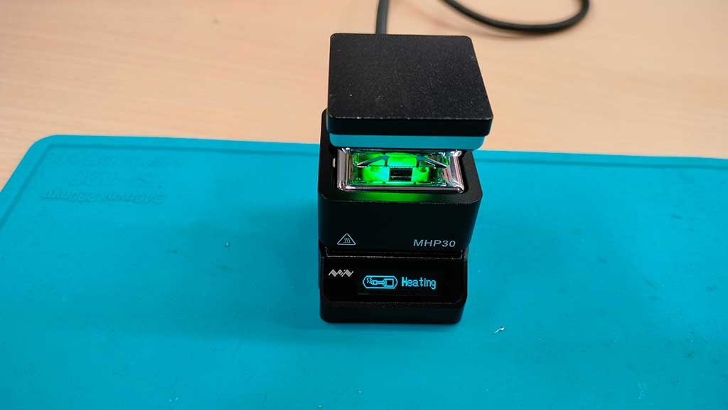
If it's hot (Is the red led on?) we place our board on the hot plate.
Now pay close attention as this looks like magic!
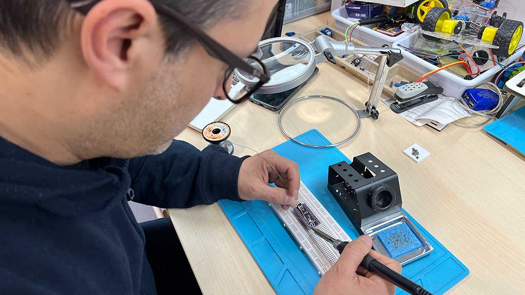
To finish I solder pins the "traditional" way, with a soldering iron.
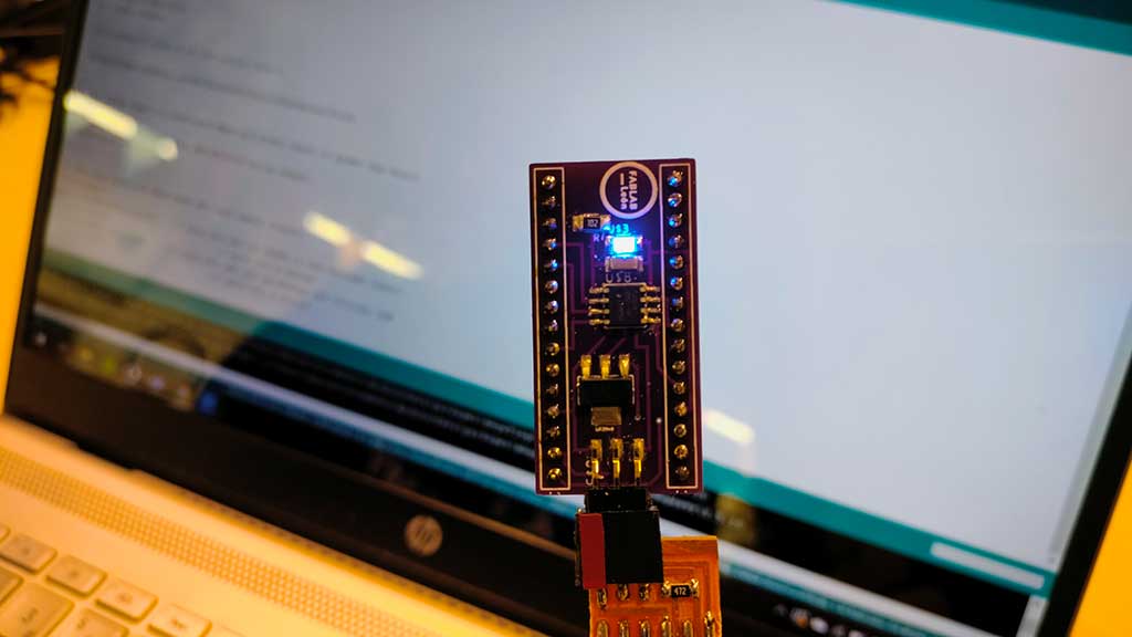
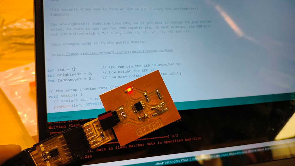
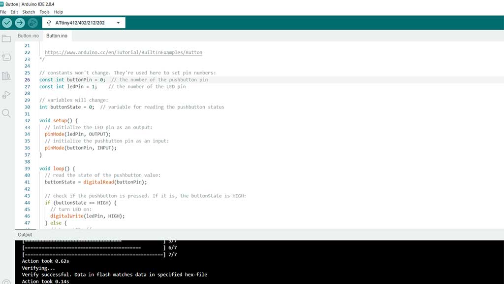
Now testing the board, making leds blink.
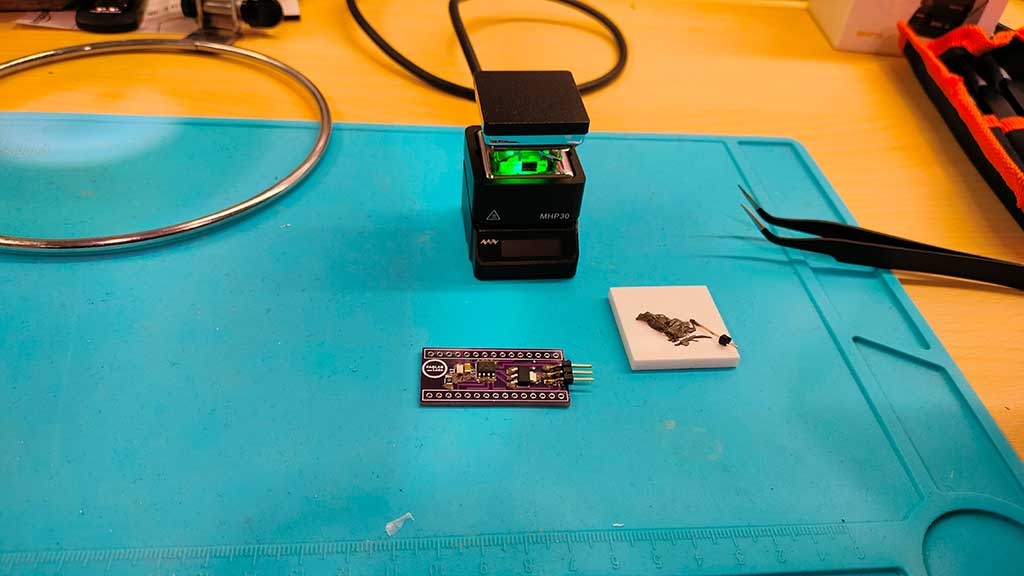
Let's move on to the boards we design and milled:
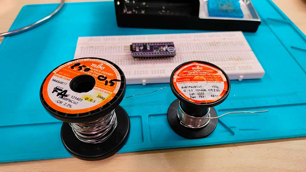
This are the tools I will be using:
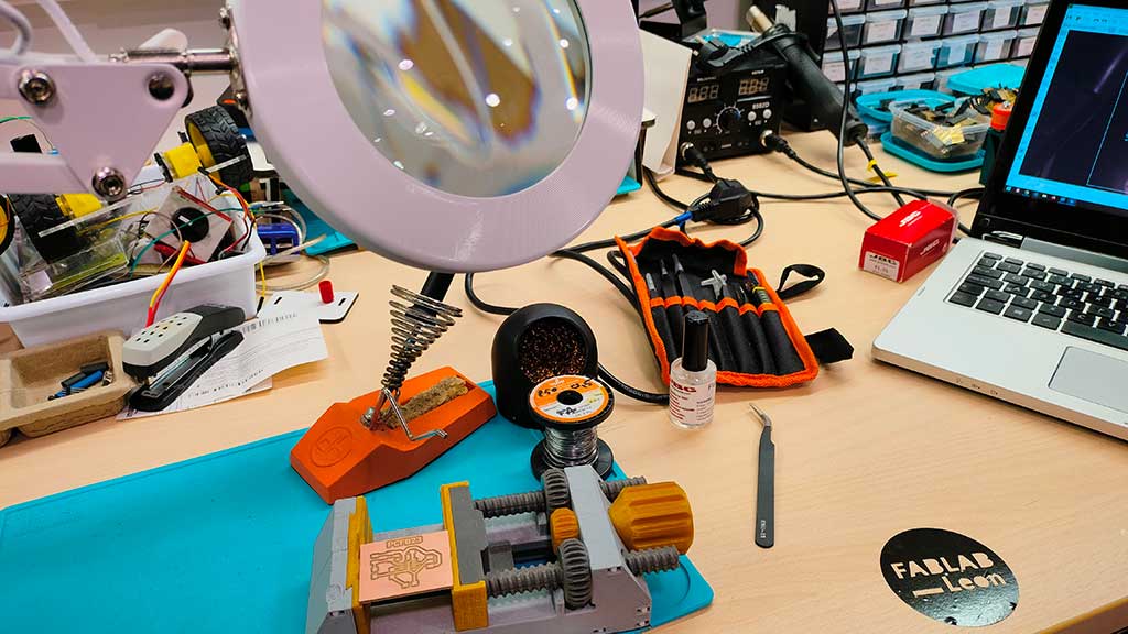
Two types of solder wire. I will be using the thinnest (it's the one on the left).
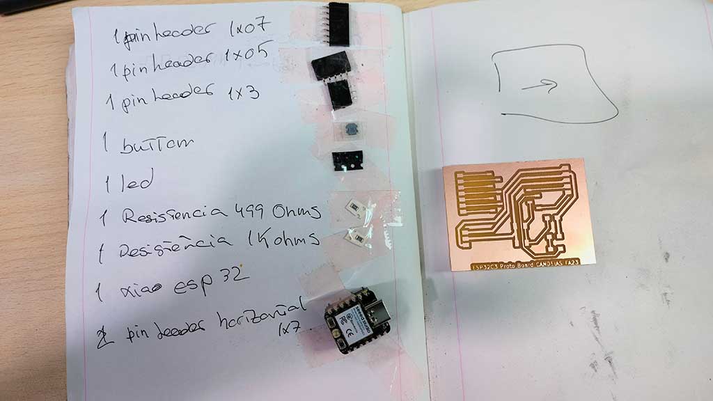
Like before, the first step is collecting the components:
Here is the BOM file:
BOM PCB ATTiny412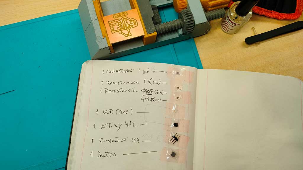
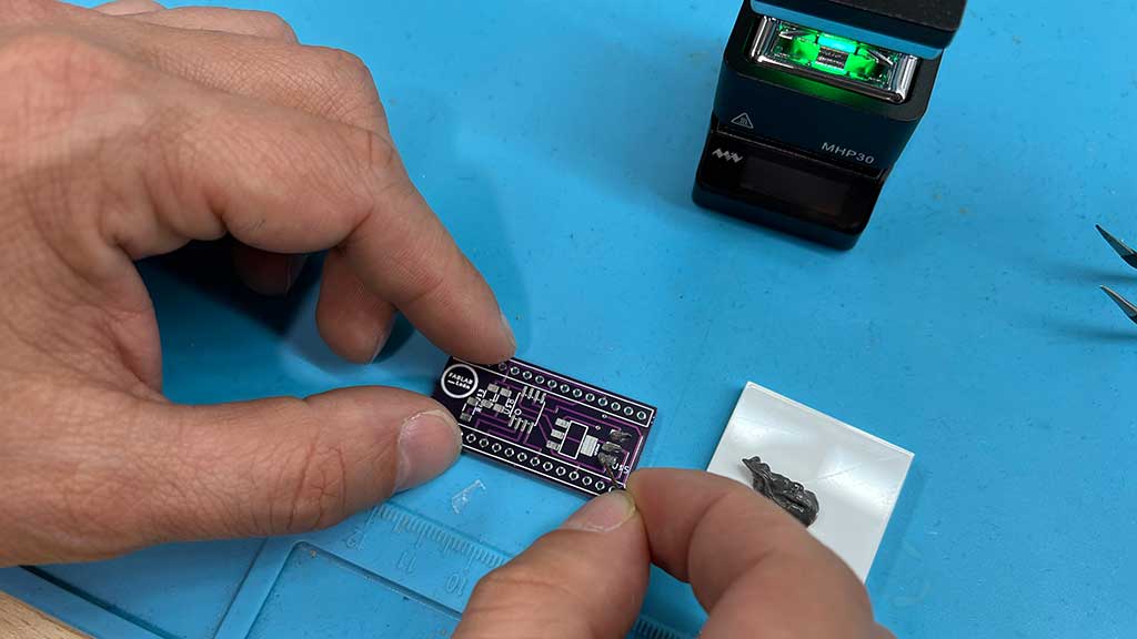
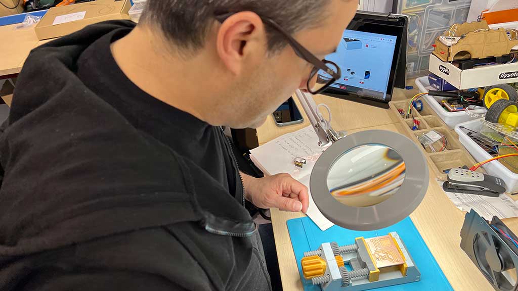
I place my board on a 3d printed support and spread flux over the contacts.
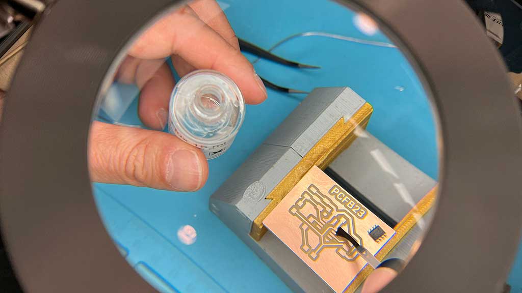
Flux aids in soldering and desoldering processes by removing oxide films which form on the surface of metals being soldered. It increases the wetting ability of the solder, causing it to flow more uniformly over surfaces.
I place the small components first. The bigger ones make placing small components hard.
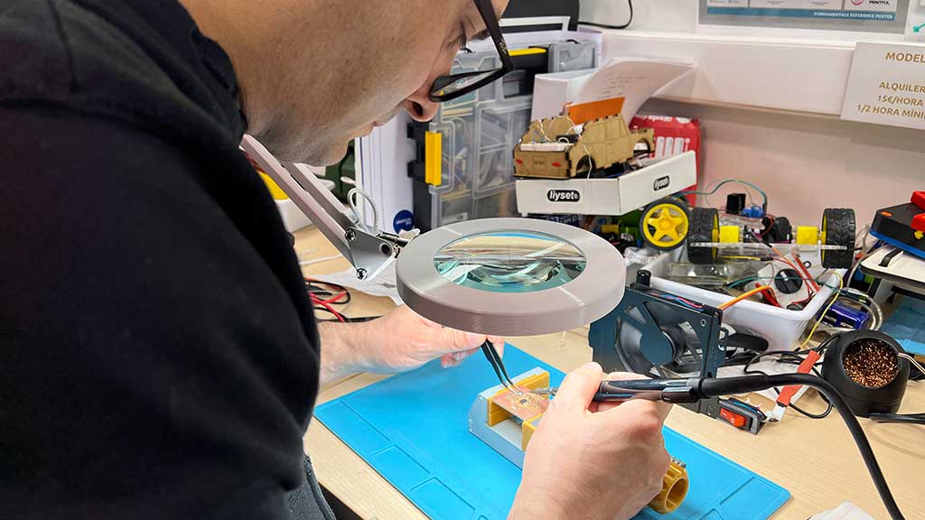
Tweezers are your friends.
Using two tweezers at the same time as I still lack fine motor skills to place such tiny components.
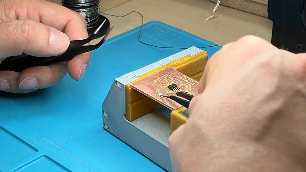
When soldering complex or smaller components, solder one contact first and then solder all the other contacts. Then return to perfect the first one.
Also be inventive: To keep the pins in place I used another set of pins.
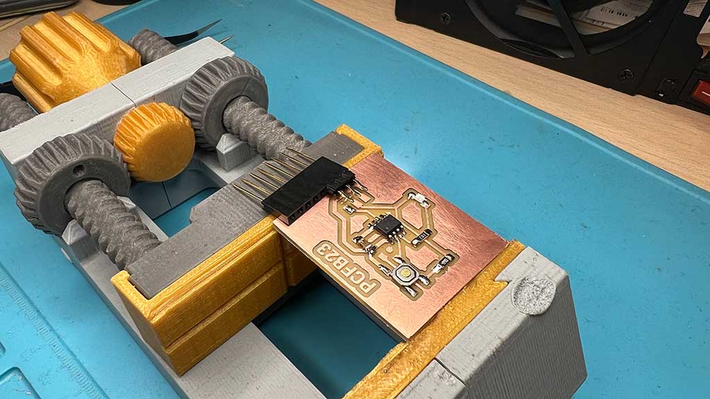
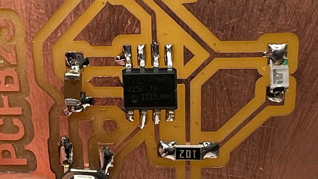
All done:
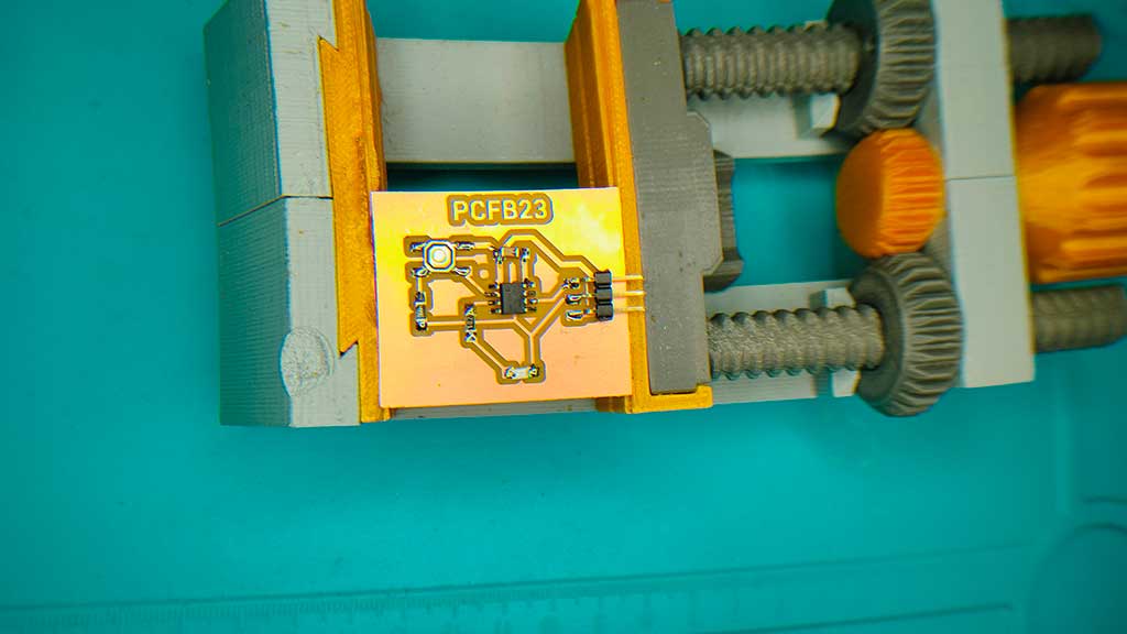
Shiny and oh so bright and yet not that well soldered.
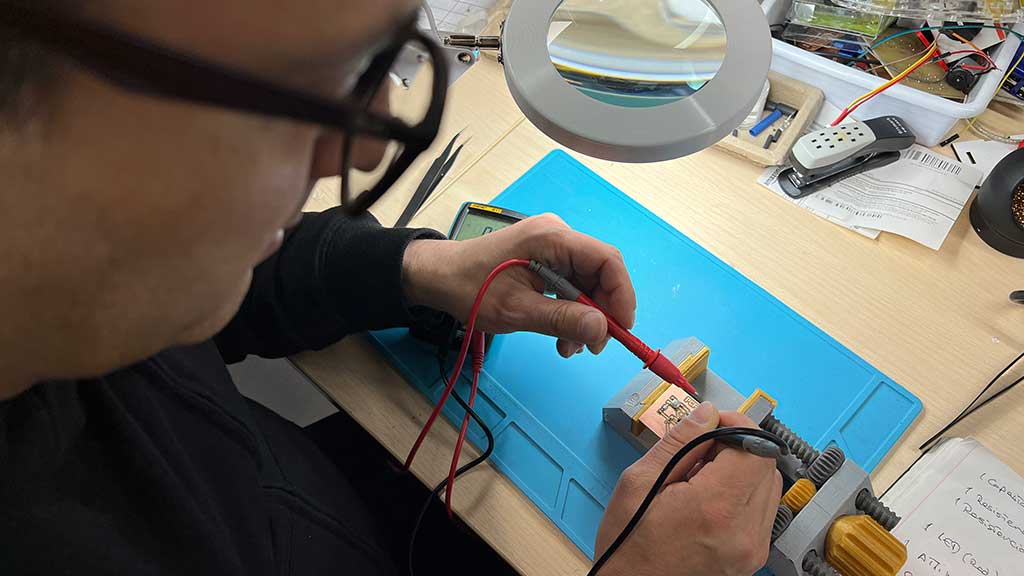
Testing for continuity
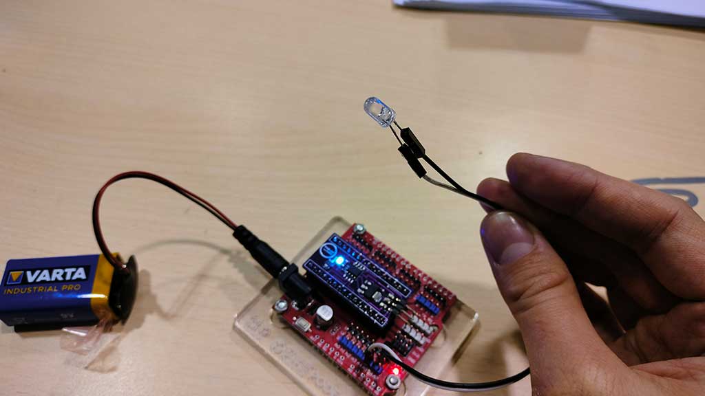
Testing a simple blink:
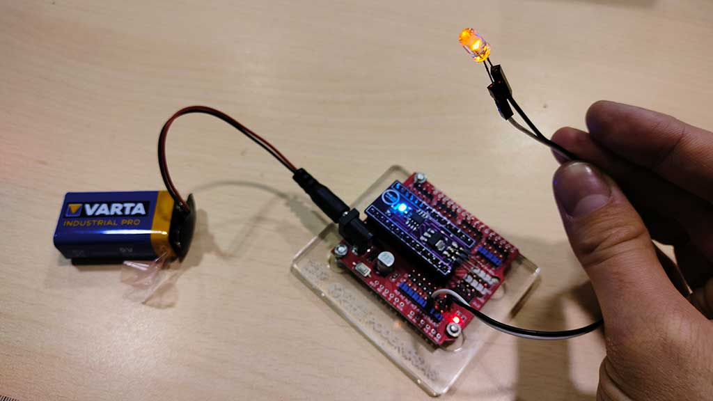
Testing the button with the led:
Making another board:
BOM PCB ATTiny412Like before, I collected the components and duct taped them to my notebook.
But this time it didn't go so perfectly.
I soldered a resistor with the wrong value and so I had to desolder it using the hot air gun.
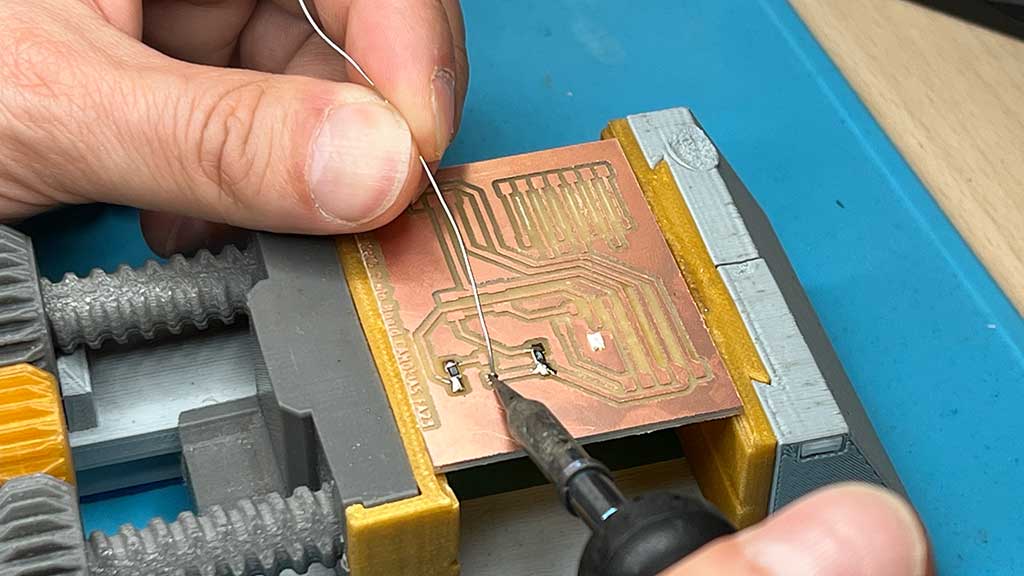
The trick to soldering these vertical terminals is to add the board so that the pieces not only stay in place but also to make sure that the board will fit.
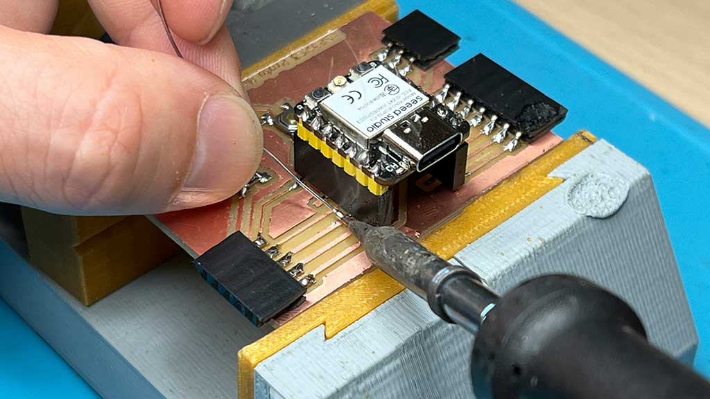
First we solder the outside pins and then the inside pins.
As you can see I burned one of the terminals, so I had to resolder again and solder new ones.
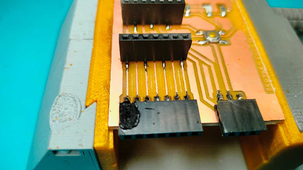
With new terminals:
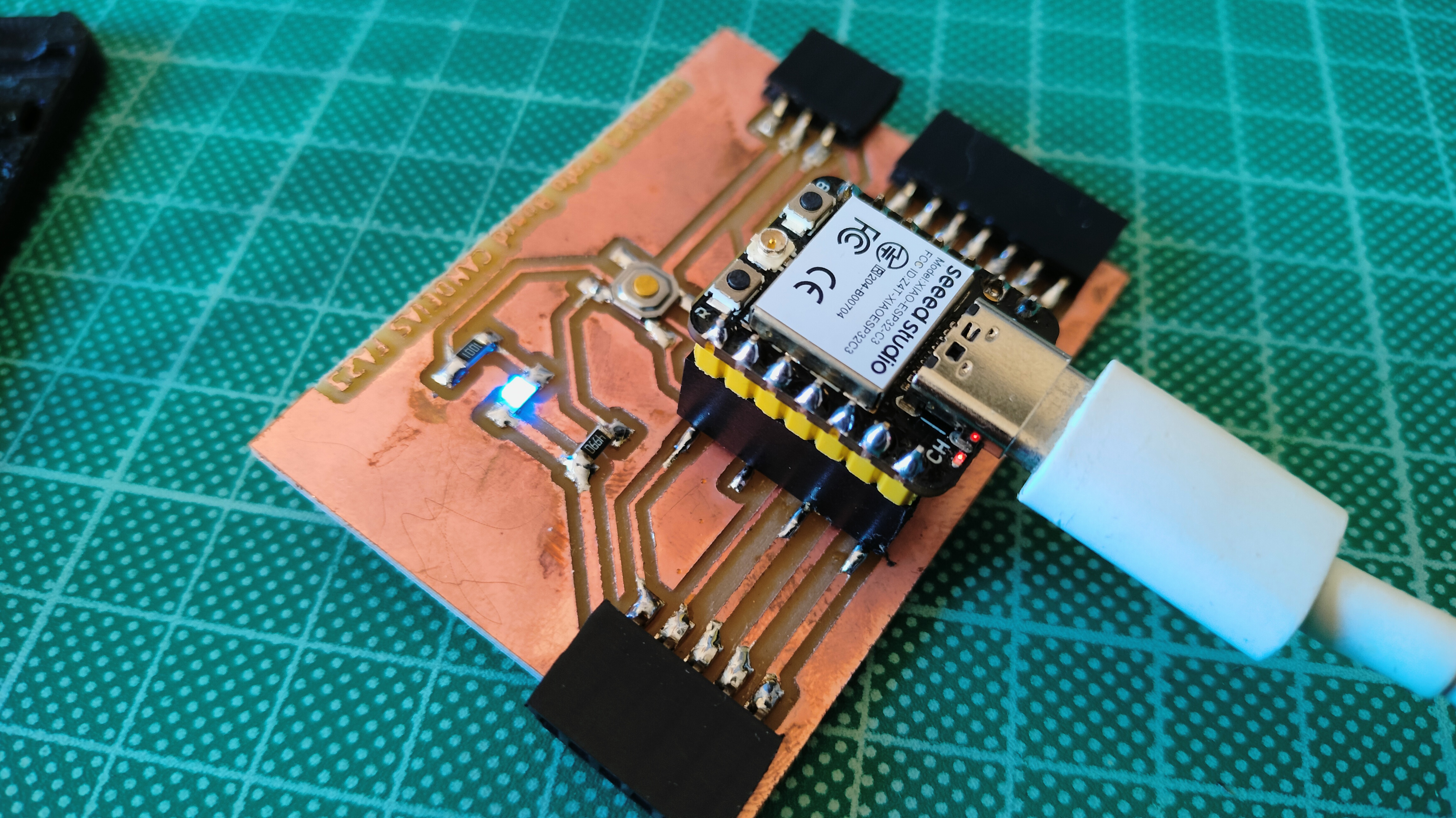
Testing the board with a simple blink.
For the final project
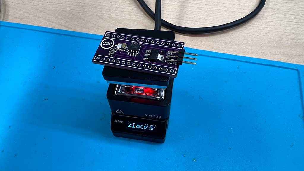
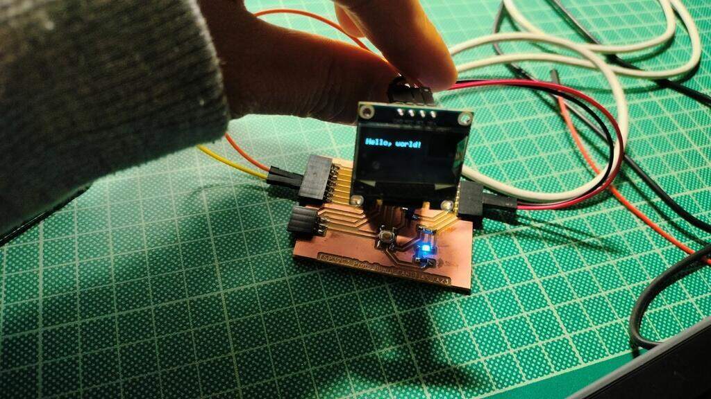
For the final project I design the Shield that will allow me to test different components without having 3 different boards soldered up.
Here is an example testing an OLED display
Files
- ATtiny412 Footprint and schematic Library from Snapeda
- Board case for PCB412, version 1, STEP File
- Board Case V1, STL File
- Shell SVG used for contour cut of the board
- PCB412 Contour cut
- PCB412 Kicad PCB file
- PCB412 Kicad Project file
- PCB412 dsn file
- PCB412 traces
- PCB412 Kicad prl File
- PCB412 schematic file
- XIAO ESP32C3 Shell PCB Kicad, DSN, SVG and PNG files
Learned this week (in no special order)
- How to safely operate a small format CNC;
- How to use the small format CNC;
- How to mill a PCB board;
- How to solder and desolder;
Notes and Thoughts
Links
Glossary:
- Runout:: The amount of runout in a machine spindle. Runout is the amount of variation in the diameter of the spindle.
- Spindle:: The spindle is the rotating part of a CNC machine that holds the cutting tool. The spindle is powered by a motor and is usually driven by belts or gears.
- Clearance:: The distance between the cutting tool and the workpiece.
- Feed rate:: The speed at which the cutting tool moves across the workpiece.
- Free:: The distance between the cutting tool and the workpiece when the spindle is not cutting.
- Plunge:: The distance the cutting tool moves into the workpiece per revolution of the spindle.
- Toolpath:: The path followed by the cutting tool.
- Workpiece: The material that is being cut.
- Fixture/Fixturing: A fixture is a device used to hold a workpiece in a fixed position while it is being machined.
- FR-1: A printed circuit board material. FR stands for flame retardant.
- FR-4: A printed circuit board material. FR stands for flame retardant.
- PCB: Printed Circuit Board.
- Gerber: A file format used to exchange PCB data between different CAD (Computer-Aided Design) software packages.
Some of these definitions were generated by AI using ChatGTP.