This week's fun assignment was:
Individual assignment:- Browse through the data sheet for your microcontroller;
- Program a microcontroller development board to interact and communicate;
- Extra credit: use different languages &/or development environments;
- Compare the performance and development workflows for other architectures;

Embedded programming
This week I tried to get to the week's assignment as soon as possible, but truth be told, that didn't
help me much in terms of time management.
I got lost reading stuff about microcontrollers s and sensors. Eventually I started creating a Glossary as
much of what I was trying to read was just gibberish for my brain.
I also found out that reading Datasheets is very boring. I guess that's not really surprising.
So, let's get to it.
Group assignment
Fab Lab León has a lot of Microcontrollers and Boards to try out and document.
Microcontrollers
XIAO ESP23-C3
| XIAO ESP23-C3 | |
|---|---|
| Processor | SP32-C3, 32 bit RISC-V single core processor |
| Flash | 4M |
| Max clock rate | 160MHz |
| GPIOs | 11 |
| ADC | 4 |
| PWM | 16 channels |
| SRAM | 400KB |
| UART | 2 |
| I2C | 1 |
| I2S | 1 |
| SPI | 1 |
| JTAG | 1 |
| USB | 1 |
| Wireless Communication | Wifi, Bluetooth, Bluetooth LE |
| Site | XIAO ESP32 Site |
What's important?
- 14 pins (11 digital pins, 4 Analog pins)
- Clock 160 MHz
- 4M Flash Memory
- 400KB SRAM
- Operating voltage: 3.3 V
Pin out
(Click the image for a larger version.)
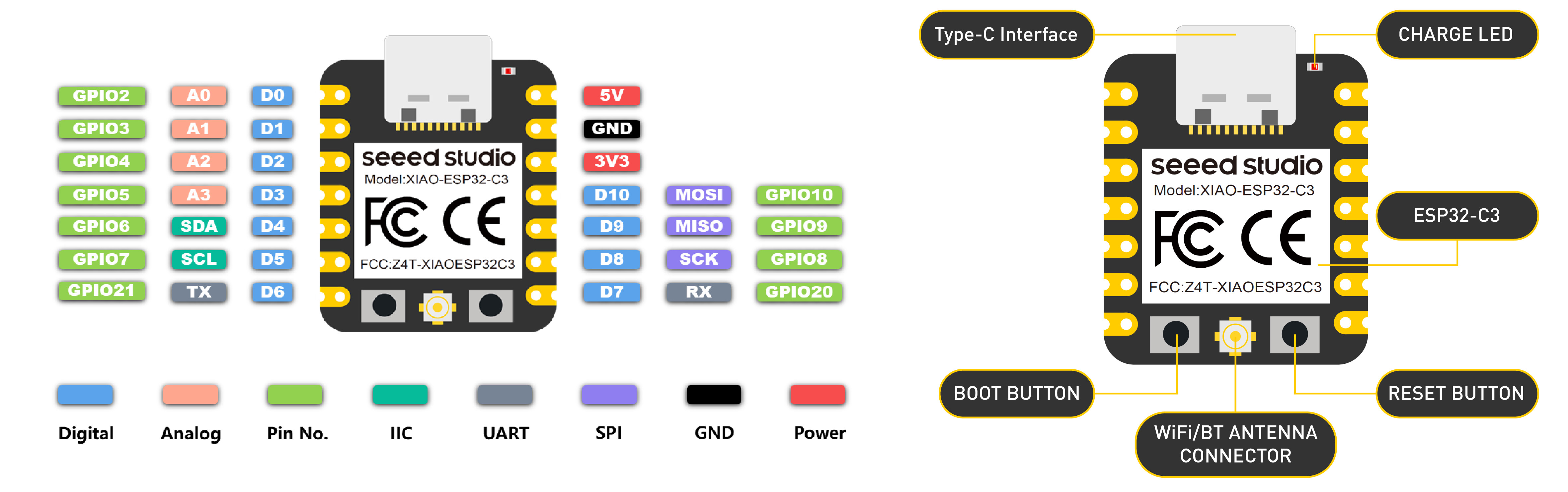
- 5V: Supply voltage 5V.
- GND: Ground.
- 3V3: Supply voltage 3V3.
- Digital pins (GPIO Pin number): D0, D1, D2, D3, D4, D5, D6, D7, D8, D9, D10, D11
- Analog pins (GPIO Pin number): A0, A1, A2, A3
- SDA (GPIO Pin number): D4
- SCL (GPIO Pin number): D5
XIAO RP2040
| RP2040 | |
|---|---|
| Processor | Dual ARM Cortex-M0+ cores |
| Flash | 2M |
| Max clock rate | 133MHz |
| GPIOs | 30 |
| PWM | 16 channels |
| SRAM | 264 KB | ADC | 3x12-bit |
| UART | 1 |
| I2C | 1 |
| SPI | 1 |
| USB | 1 |
| Site | XIAO RP2040 Site |
What's important?
- 14 pins
- Clock 133 MHz
- 2M Flash Memory
- 264KB SRAM
- Operating voltage: 3.3 V
Pin out
(Click the image for a larger version.)
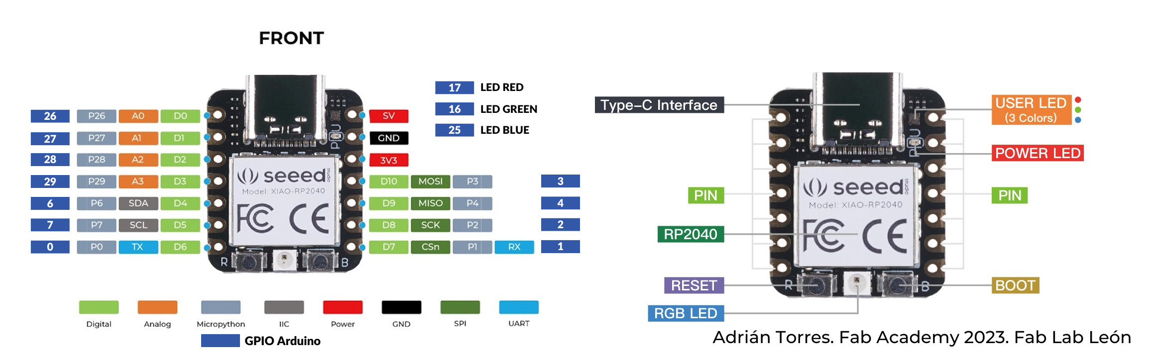
- 5V: Supply voltage 5V.
- GND: Ground.
- 3V3: Supply voltage 3V3.
- Digital pins (GPIO Pin number): 0, 1, 2, 3, 4, 6, 7, 26, 27, 28, 29
- Analog pins (GPIO Pin number): 26, 27, 28, 29
- LED Green (GPIO Pin number): 16
- LED Red (GPIO Pin number): 17
- LED Blue (GPIO Pin number): 25
- SDA (GPIO Pin number): 6
- SCL (GPIO Pin number): 7
- RGB LED_POWER (GPIO Pin number): 11
- RGB LED (GPIO Pin number): 12
XIAO SAMD21
| SAM D21 | |
|---|---|
| Max clock rate | 48MHz |
| Pins | 14 |
| GPIOs | 11 |
| Flash | 256KB |
| SRAM | 32KB |
| USB interface | yes |
| LED | 1 |
| DAC | 1 |
| Site | SAM D21 Site |
What's important?
- 14 pins
- Clock 48 MHz
- 256KB Flash Memory
- 32KB SRAM
- Operating voltage:3.3 V
Communications
- 1 I2C interface
- 1 UART interface
- 1 SPI interface
- USB Type-C interface
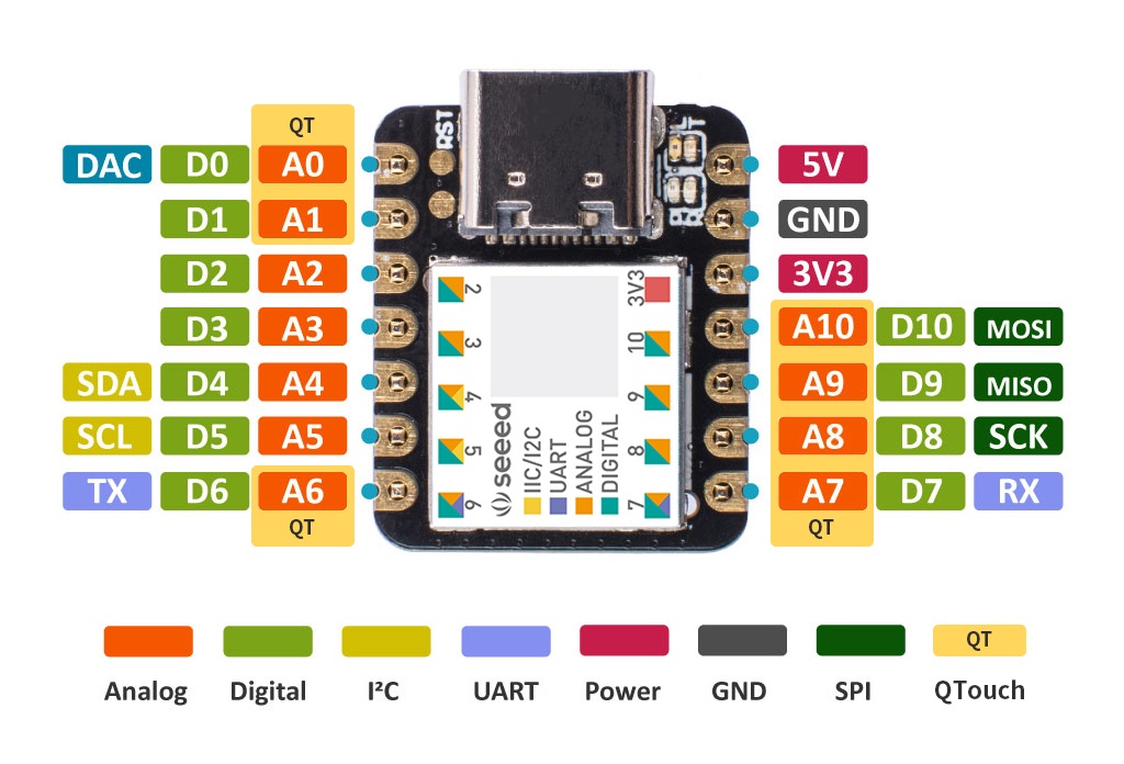
Pin out
(Click the image for a larger version.)
| SAM D11C | |
|---|---|
| Max clock rate | 48MHz |
| Pins | 14 |
| GPIOs | 12 |
| Flash | 16KB |
| SRAM | 4KB |
| USB interface | yes |
| ADC | 5 |
| AC | 2 |
| DAC | 1 |
| Site | SAM D11C Site |
What's important?
- 14 pins
- Clock 48 MHz
- 16 KB Flash Memory
- 4KB SRAM
- Operating voltage:1.62V - 3.63 V
Communications
- USART: RX: PA31, PA05 | TX: PA30, PA04).
- SPI: MOSI: PA04,PA08 | MISO: PA14,PA30 | SCK: PA09 | SS: PA15 .
- TWI (I2C): SDA:PA14 | SCL: PA15.
Pin out
(Click the image for a larger version.)
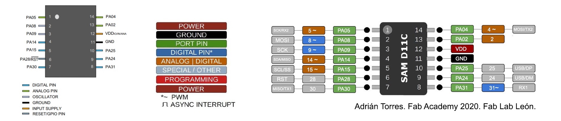
- VDD: Supply voltage.
- GND: Ground.
- Digital pins:PA02, PA04, PA05, PA08, PA09, PA14, PA15, PA31.
- Analog pins: PA02, PA04, PA05, PA14, PA15.
- USB pins: PA24, PA25.
| ATtiny1614 | |
|---|---|
| Max clock(MHz) | 20 |
| Flash (KiB) | 16 |
| SRAM (bytes) | 2048 |
| EEPROM (bytes) | 256 |
| UART | USART* |
| I²C (TWI) | master, slave |
| SPI | master, slave |
| Timers 8/12/16 (bits) | 0 / 1 / 2 / R |
| PWM | yes |
| ADC pins | 10 |
| GPIO pins | 12 |
| IC Packages | SO150-14 |
| GCC arch ID | avrxmega3 |
| Program / Debug | UPDI |
| Site | ATtiny1614 Site |
What's important?
- 14 pins
- Clock 20 MHz
- 16 KB Flash Memory
- 256 B EEPROM
- 2 KB SRAM
- Maximum voltage: 6V; minimum voltage -0.5 V
Communications
- USART: RX: PA31, PA05 | TX: PA30, PA04).
- SPI: MOSI: PA04,PA08 | MISO: PA14,PA30 | SCK: PA09 | SS: PA15 .
- TWI (I2C): SDA:PA14 | SCL: PA15.
Pin out
(Click the image for a larger version.)
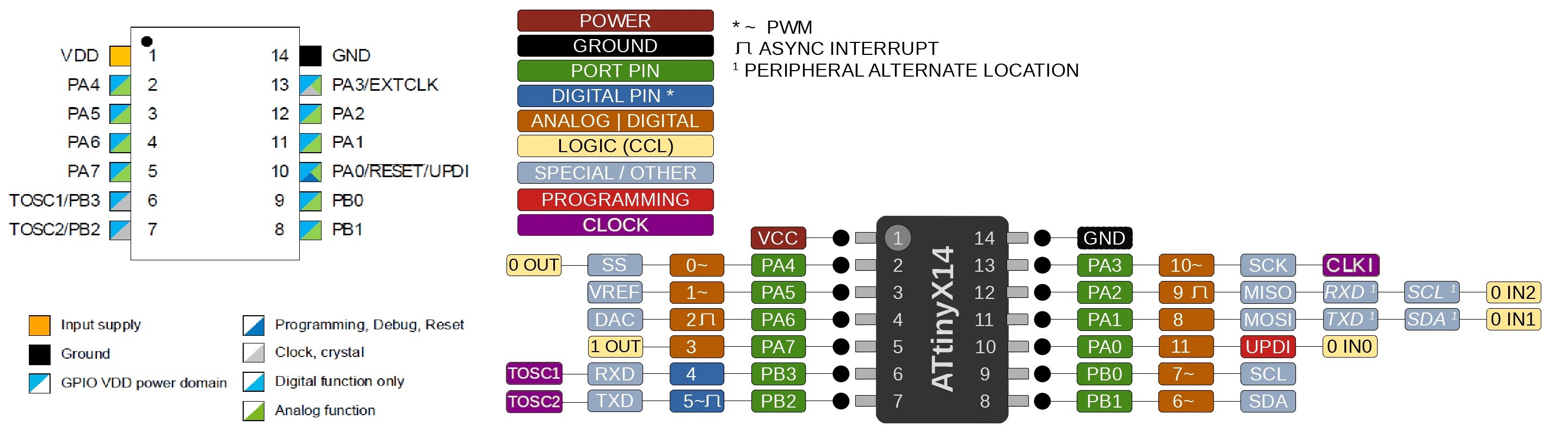
- VDD: Supply voltage.
- GND: Ground.
- Digital pins: Port A: PA0, PA1, PA2, PA3, PA4, PA5, PA6, PA7. Port B: PB0, PB1, PB2, PB3.
- Analog pins: PA1, PA2, PA3, PA4, PA5, PA6, PA7. Port B: PB0, PB1.
- UPDI Programming pin: PA0 (physical pin number 10).
- External Clock Pin: PA3.
Specifications comparison: XIAO RP2040 vs XIAO ESP32-C3 vs Seeduino XIAO SAMD21
| Board | XIAO ESP32-C3 | XIAO SAMD21 | XIAO RP2040 |
|---|---|---|---|
| Processor | ESP32-C3 32-bit RISC-V @160MHz | SAMD21 M0+@48MHz | RP2040 Dual-core M0+@133Mhz |
| Wireless Connectivity | WiFi and Bluetooth 5 (LE) | N/A | N/A |
| Memory | 400KB SRAM, 4MB onboard Flash | 32KB SRAM 256KB FLASH | 264KB SRAM 2MB onboard Flash |
| Built-in Sensors | N/A | N/A | N/A |
| Interfaces | I2C/UART/SPI/I2S | I2C/UART/SPI | I2C/UART/SPI |
| PWM/Analog Pins | 11/4 | 11/11 | 11/4 |
| Onboard Buttons | Reset/ Boot Button | N/A | Reset/ Boot Button |
| Onboard LEDs | Charge LED | N/A | Full-color RGB/ 3-in-one LED |
| Battery Charge Chip | Built-in | N/A | N/A |
| Programming Languages | Arduino | Arduino/ CircuitPython | Arduino/ MicroPython/ CircuitPython |
Performance compare of different architectures:
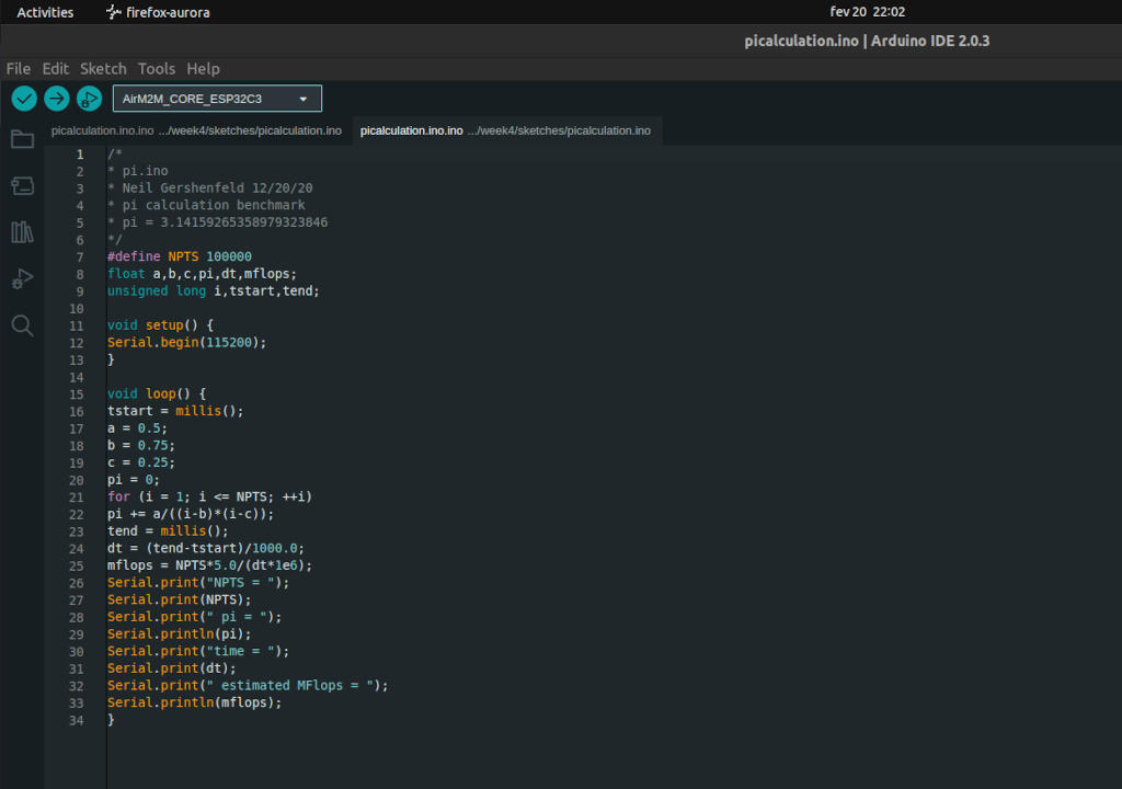
To compare the performance of the different architectures, I have chosen to use the same code for all three boards. The code is a "pi calculation benchmark" and was written by Professor Neil Gershenfeld. The code is as follows:
/*
* pi.ino
* Neil Gershenfeld 12/20/20
* pi calculation benchmark
* pi = 3.14159265358979323846
*/

#define NPTS 100000

float a,b,c,pi,dt,mflops;
unsigned long i,tstart,tend;

void setup() {
    Serial.begin(115200);
    }

void loop() {
    tstart = millis();
    a = 0.5;
    b = 0.75;
    c = 0.25;
    pi = 0;
    for (i = 1; i <= NPTS; ++i)
        pi += a/((i-b)*(i-c));
    tend = millis();
    dt = (tend-tstart)/1000.0;
    mflops = NPTS*5.0/(dt*1e6);
    Serial.print("NPTS = ");
    Serial.print(NPTS);
    Serial.print(" pi = ");
    Serial.println(pi);
    Serial.print("time = ");
    Serial.print(dt);
    Serial.print(" estimated MFlops = ");
    Serial.println(mflops);
}
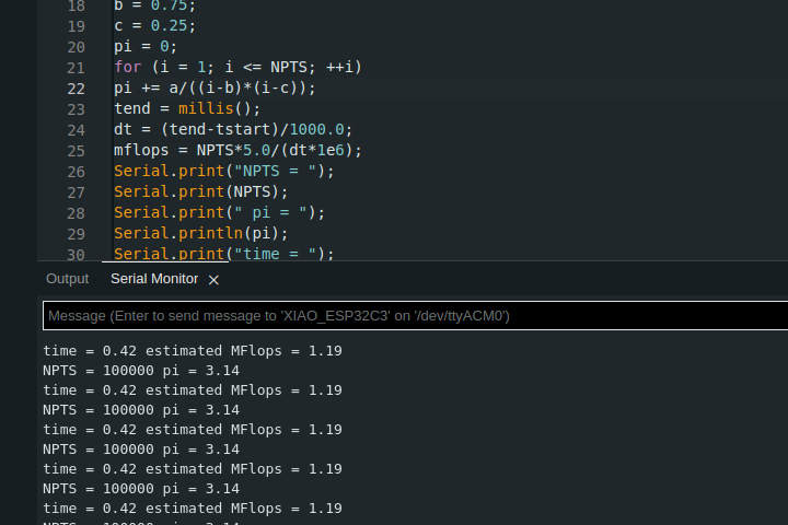
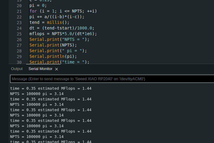
The results are as follows:
| Board | XIAO ESP32C3 | XIAO RP2040 | XIAO SAMD21 |
|---|---|---|---|
| Processor | ESP32-C3 32-bit RISC-V @160MHz | RP2040 Dual-core M0+@133Mhz | SAMD21 M0+@48MHz |
| Time | 0.35 | 0.42 | 2.49 |
| Estimated MFlops | 1.44 | 1.19 | 0.20 |
Unexpected results? Not really!
The code can be found here along with many other samples: Pi Calculation benchmark
The workflow for these two boards is the same. I will try to update this table later using SAMDINO.
Individual assignment
For the individual assignment I will try different IDE's as well as using C and MicroPython.
Arduino IDE
Installing Arduino IDE in Linux was a breeze.
There are a lot of ways to do it, so I won't go into detail as that is not the assignment but it's as
simple as:
sudo snap install arduino
sudo chmod a+rw /dev/ttyACM0 (or ttyWHATEVER you need).If that works, add the user to the dialout group:
sudo usermod -a -G dialout $USER
After installing the IDE we must add some libraries and boards. To add the XIAO ESP32:
Navigate to File > Preferences, and fill "Additional Boards Manager URLs" with the following url's
https://raw.githubusercontent.com/espressif/arduino-esp32/gh-pages/package_esp32_index.json
http://drazzy.com/package_drazzy.com_index.json
https://github.com/earlephilhower/arduino-pico/releases/download/global/package_rp2040_index.json
After installing the Arduino IDE, I installed Thonny IDE.
Thonny is an integrated development environment for Python that is designed for beginners. It was created by Aivar Annamaa, an Estonian programmer. You can find the link in the Links section.
And just for the fun of it, another way to install software in Linux:
sudo apt install thonny
Lastly, I installed the Arduino extension on VS Code and I will try to use it for the rest of the course as I already use VS Code.
Up next...blinking LEDs!
As everything is installed, I will jump do blinking a LED in the XIAO RP2040, with the FAB-XIAO board
First, I will use the Arduino IDE using C.
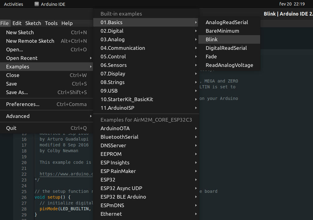
I start by loading the blink.ino example from the Arduino IDE.
First I will blink the integrated LED:
You can find the blink example in the Arduino IDE in Files > Examples > Basic > Blink
After uploaded the code:
Now let's try to blink the LED on the board using the button also on the board.
Adrián's documentation mentions the GPIO pin as 0 for the LED.
I have to change a few things in the code:
- Change the pin to 0
- Add a int as the pin number
- Change LED_BUILTIN to pinled
Here's the sketch:
int pinled = 0;

void setup() {
    pinMode(pinled, OUTPUT);
}
void loop() {
    digitalWrite(pinled, HIGH);  // turn the LED on (HIGH is the voltage level)
    delay(1000);                      // wait for a second
    digitalWrite(pinled, LOW);   // turn the LED off by making the voltage LOW
    delay(1000);                      // wait for a second
}
So, now I will try to turn the LED on with the push of a button:
From Adrián's documentation I know that the integrated button is on PIN 1 - GPIO 1 pin
const int btnPin = 1;

const int ledPin = 0;

int btnState = 0;

void setup() {
    pinMode(ledPin, OUTPUT);
    pinMode(btnPin, INPUT);
}
void loop() {
    btnState = digitalRead(btnPin);
    if(btnState == HIGH) {
        digitalWrite(ledPin, HIGH);
    } else {
        digitalWrite(ledPin, LOW);
    }
}
Cool. Pretty easy, right?
Now, let's try to do the same thing with Thonny IDE.
First, I will try to blink the integrated LED using MicroPython.
First we have to set Thonny for th3146267583 e RP2040. We can follow this tutorial Seed Studio XIAO RP2040 with MicroPython
After setting up the board, we can start coding.
from machine import Pin, Timer

    led = Pin(25, Pin.OUT)
Counter = 0
Fun_Num = 0

def fun(tim):
    global Counter
    Counter = Counter + 1
    print(Counter)
    led.value(Counter%2)

tim = Timer(-1)
tim.init(period=1000, mode=Timer.PERIODIC, callback=fun)
Ok, now let's light up the integrated led
from ws2812 import WS2812
import utime
import machine
power = machine.Pin(0,machine.Pin.OUT)
power.value(1)
BLACK = (0, 0, 0)
RED = (255, 0, 0)
YELLOW = (255, 150, 0)
GREEN = (0, 255, 0)
CYAN = (0, 255, 255)
BLUE = (0, 0, 255)
PURPLE = (180, 0, 255)
WHITE = (255, 255, 255)
COLORS = (BLACK, RED, YELLOW, GREEN, CYAN, BLUE, PURPLE, WHITE)

led = WS2812(12,1)#WS2812(pin_num,led_count)

while True:
    print("Beautiful color")
    for color in COLORS:
        led.pixels_fill(color)
        led.pixels_show()
        utime.sleep(0.2)
Ok, that's done. Just one more example and we can leave MicroPython.
Light up the integrated LED in FAB-XIAO using the integrated button:
from machine import Pin
led = Pin(0, Pin.OUT)
button = machine.Pin(1, machine.Pin.IN, machine.Pin.PULL_UP)

while True:
    if button.value():
        led.toggle();
Glossary:
IC: Integrated circuit or monolithic integrated circuit (also referred to as an IC, a chip, or a microchip) is a set of electronic circuits on one small flat piece (or "chip") of semiconductor material, usually silicon. Large numbers of miniaturized transistors and other electronic components are integrated together on the chip. This results in circuits that are orders of magnitude smaller, faster, and less expensive than those constructed of discrete components, allowing a large transistor count.
UPDI:
The Unified Program and Debug Interface (UPDI) is a Microchip proprietary interface for external programming and on-chip debugging of a device. It is a successor to the PDI two-wire physical interface, which is found on all AVR XMEGA devices.Wafer: A Wafer is a thin slice of semiconductor material, such as silicon, used to manufacture integrated circuits (ICs). Wafers are typically round, flat, and made of a single crystal of semiconductor material. Wafers are typically 300 mm in diameter and 750 micrometers thick. Wafers are made of silicon, gallium arsenide, or indium phosphide.
GPIO: General-purpose input/output (GPIO) is a digital signal pin on an integrated circuit orvis
GCC: The GNU Compiler Collection (GCC) is a compiler system produced by the GNU Project supporting
PWM: Pulse-width modulation (PWM) is a modulation technique used to encode a message into a pulsing signal.
SPI: Serial Peripheral Interface (SPI) is a synchronous serial data protocol used by microcontrollers for
I²C: Inter-Integrated Circuit (I²C) is a synchronous serial data protocol, developed by Philips in 1982
TWI: Two Wire Interface (I2C): The Two Wire Interface (TWI) is a serial communication protocol used in many microcontrollers and peripheral ICs. It is a multi-master, multi-slave, single-ended, serial bus with a two-wire interface. It is a synchronous serial protocol, meaning that the clock signal must be generated externally and synchronized with the data signal. The TWI protocol is a subset of the I2C protocol, which is a subset of the Philips I2C protocol. The TWI protocol is also known as the I2C protocol.
UART: Universal asynchronous receiver-transmitter (UART) is a computer hardware device for asynchronous serial communication in which the data format and transmission speeds are configurable.
EEPROM: Electrically erasable programmable read-only memory (EEPROM) is a type of non-volatile memory used in computers and other electronic devices.
SRAM: Static random-access memory (SRAM) is a type of random-access memory (RAM) that uses static memory cells.
Flash: Flash memory is an electronic (solid-state) non-volatile computer storage medium that can be electrically erased and reprogrammed.
Max clock: The maximum clock frequency of the microcontroller.
Timers: A timer is a device that produces a series of pulses at regular intervals.
ADC: Analog-to-digital converter (ADC) is a device that converts an analog signal into a digital signal.
IC Packages: An integrated circuit (IC), sometimes called a chip or microchip, is a semiconductor wafer on which thousands or millions of tiny resistors, capacitors, and transistors are etched. The IC is the basic building block of modern electronics. It is made by depositing multiple layers of metal and silicon on a wafer, and then using photolithography and chemical etching to define the individual components.
ARM: ARM is a family of reduced instruction set computing (RISC) architectures for computer processors, configured for various environments. ARM also designs cores that are licensed to other semiconductor companies, which design their own systems-on-chip (SoCs) based on ARM cores. The ARM architecture is widely used in mobile phones, tablets, digital televisions, and other electronic devices.
RISC: Reduced instruction set computing (RISC) is a computer design philosophy that emphasizes simplicity and efficiency. RISC processors have a small number of general-purpose registers and a simple instruction set. RISC processors are typically used in embedded systems, such as mobile phones, digital televisions, and video game consoles.
CISC: Complex instruction set computing (CISC) is a computer design philosophy that emphasizes flexibility and efficiency. CISC processors have a large number of general-purpose registers and a complex instruction set. CISC processors are typically used in desktop computers and servers.
USART: Universal Synchronous and Asynchronous Receiver and Transmitter is a type of
communication interface that allows a microcontroller to communicate with other devices. USARTs are
commonly used in embedded systems to communicate with other devices, such as sensors, displays, and
other microcontrollers.
RX: RX is an abbreviation for receive. RX is used to describe the direction of data transfer in a communication protocol. For example, in the UART protocol, RX is used to describe the direction of data transfer from the UART to the microcontroller.
TX: TX is an abbreviation for transmit. TX is used to describe the direction of data transfer in a communication protocol. For example, in the UART protocol, TX is used to describe the direction of data transfer from the microcontroller to the UART.
ACD: Analog-to-digital converter (ADC) is a device that converts an analog signal into a digital signal.
DAC: Digital-to-Analog Converter (DAC) is a device that converts a digital signal into an analog signal.
Analog Comparators (AC): An analog comparator is a device that compares two analog voltages and outputs a digital signal. Analog comparators are commonly used in embedded systems to compare the voltage of a sensor to a reference voltage.
TCC: Timer Counter Control (TCC) is a type of timer that is used to generate a PWM signal.
TC: Timer Counter (TC) is a type of timer that is used to generate a PWM signal.
SOIC: Small Outline Integrated Circuit (SOIC) is a type of integrated circuit (IC) package that is commonly used in embedded systems. SOIC packages are small, thin, and have a flat, rectangular shape. SOIC packages are commonly used in embedded systems because they are inexpensive, easy to solder, and have a small footprint.
VDD: VDD is an abbreviation for supply voltage. VDD is the voltage that is supplied to the microcontroller. The VDD voltage is typically 3.3V or 5V.
GND: GND is an abbreviation for ground. GND is the reference voltage for the microcontroller. The GND voltage is typically 0V.
IDE: Integrated Development Environment (IDE) is a software application that provides comprehensive facilities to computer programmers for software development. IDEs typically include a source code editor, build automation tools, and a debugger. IDEs are commonly used in embedded systems because they provide a convenient way to develop and debug software.
Some of these definitions were generated by AI using ChatGTP.
Final project
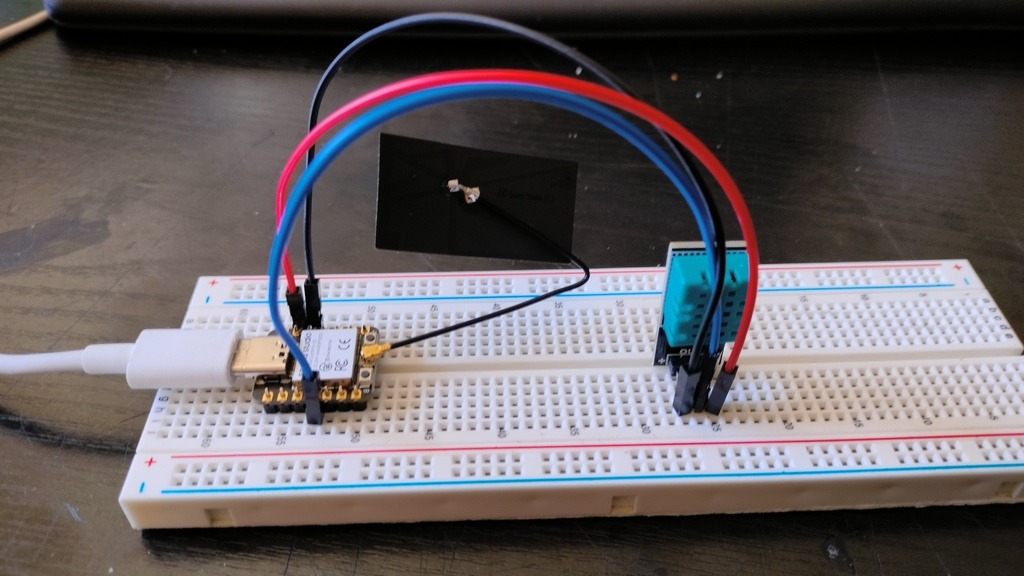
As a development step for my Final project I'm going to try to use a temperature and humidity sensor with the XIAO ESP32C3.
For this I'm going to use the DHT11 sensor and a Webserver to display the results.
First I'm going to get the readings from the sensor:
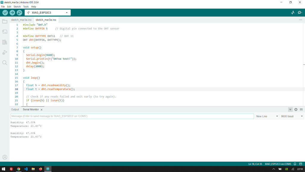
For this to work I had to import a library, the DHT.h library.
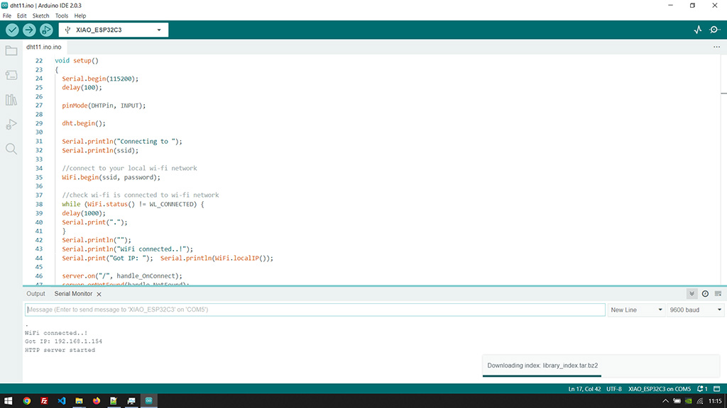
Now, I'm going to try to establish a Webserver.
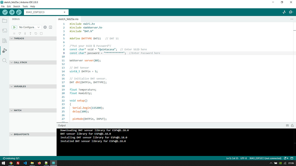
For this to work I had to import a library, the WiFi.h library and also the Webserver.h.
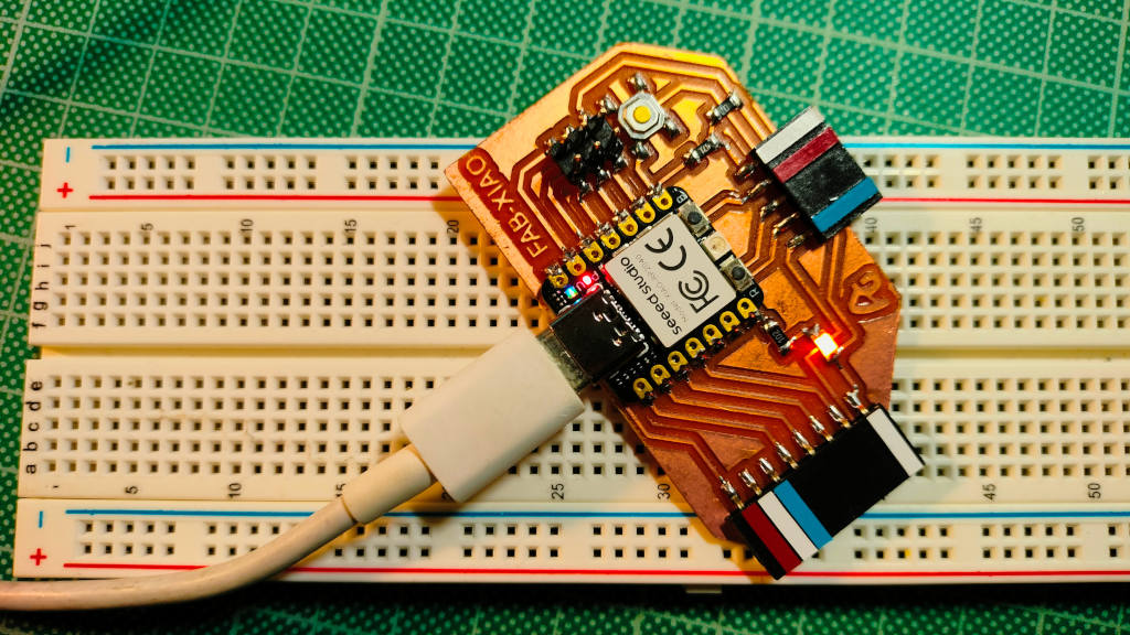
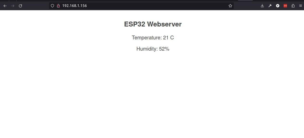
Now, I'm going to try to display the readings on the Webserver.
And here is a picture of the setup on a breadboard.
Files
Learned this week (in no special order)
- So many new words!
- Difference between coding and programming;
- Some MicroPyton
- Some C
- How boring it is to read datasheets! :D
- That we need to add the user to the dialout group
Notes and Thoughts
This week was all about trying out stuff and there is so much more to try out!
With time I hope to get better at scanning datasheets.
I have to do better time management or start managing my expectations.
I can clearly see how powerful electronics are to bring an idea to reality.
Not fond of breadboards as they seem to fail a lot. Also, I would like to find an easier way to prototype.
Links
- Adrián Torres Fab Academy site
- SpenceKonde website
- MicroChip
- GitHub Barduino
- Seeed Studio XIAO ESP32-C3
- Session 4 Embedded Programming
- Coding VS Programming
- ESP32 Arduino
- Thonny IDE
- How to use VS Code to create and Upload Arduino Sketches
- pi calculation benchmark