Fab Lab Reykjavík Group Assignments
This site is the group assignment page for Hafey and Andri in Fabacademy 2023
Week 3
Characterize your lasercutter's focus, power, speed, rate, kerf, joint clearance and types
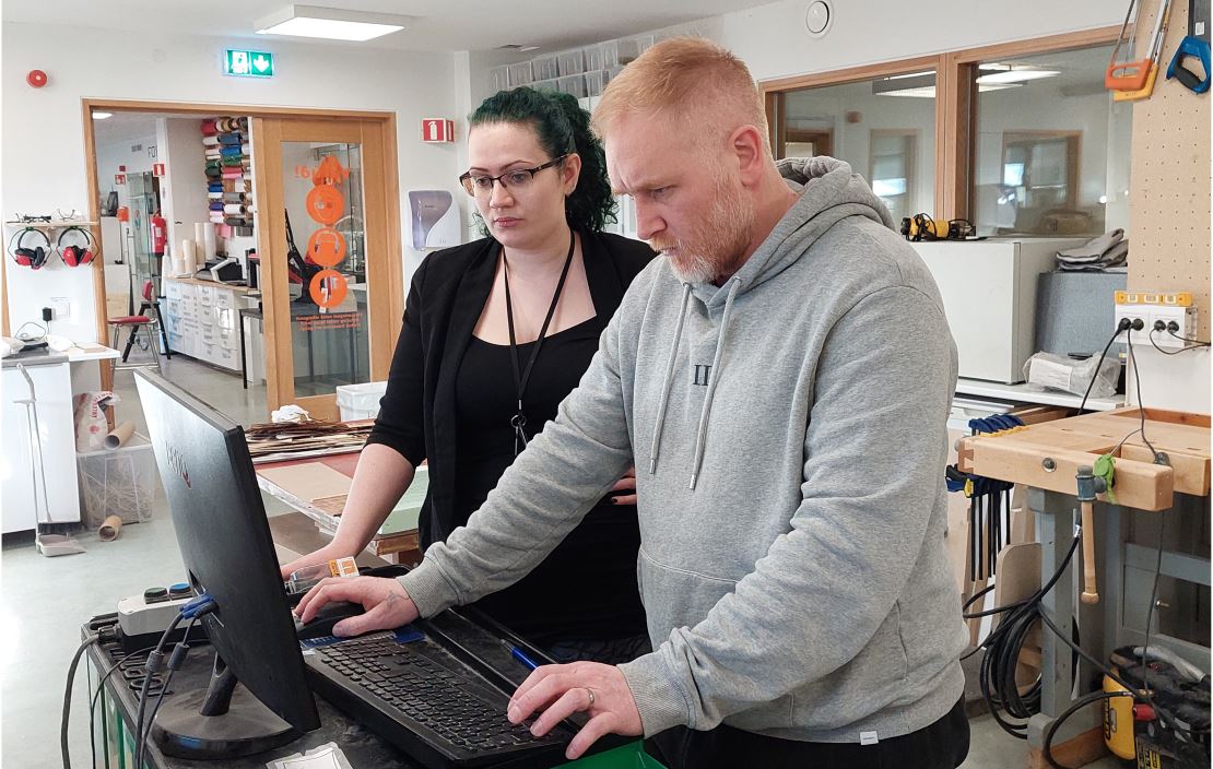
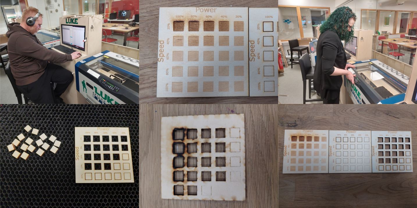
Group assignment week 3 Andri and Hafey performed in Fab Lab Reykjavík. The lasers in the lab are Epiloge mini. We made a file with a grid to show rastering with different power and speed settings (see image) we used 600 dpi We did the same file as the raster, just took the fill out and put cutting lines (see image) but like you see it did not go through the wood so we did the same but with slower setting, there a lot of them cut through but as you can see on the image of the back some were too slow. These tests make since, since the settings we use for cutting wood in the laser cutter here in Fab Lab Reykjavík are Raster 60/100 and vector 11/100/500.
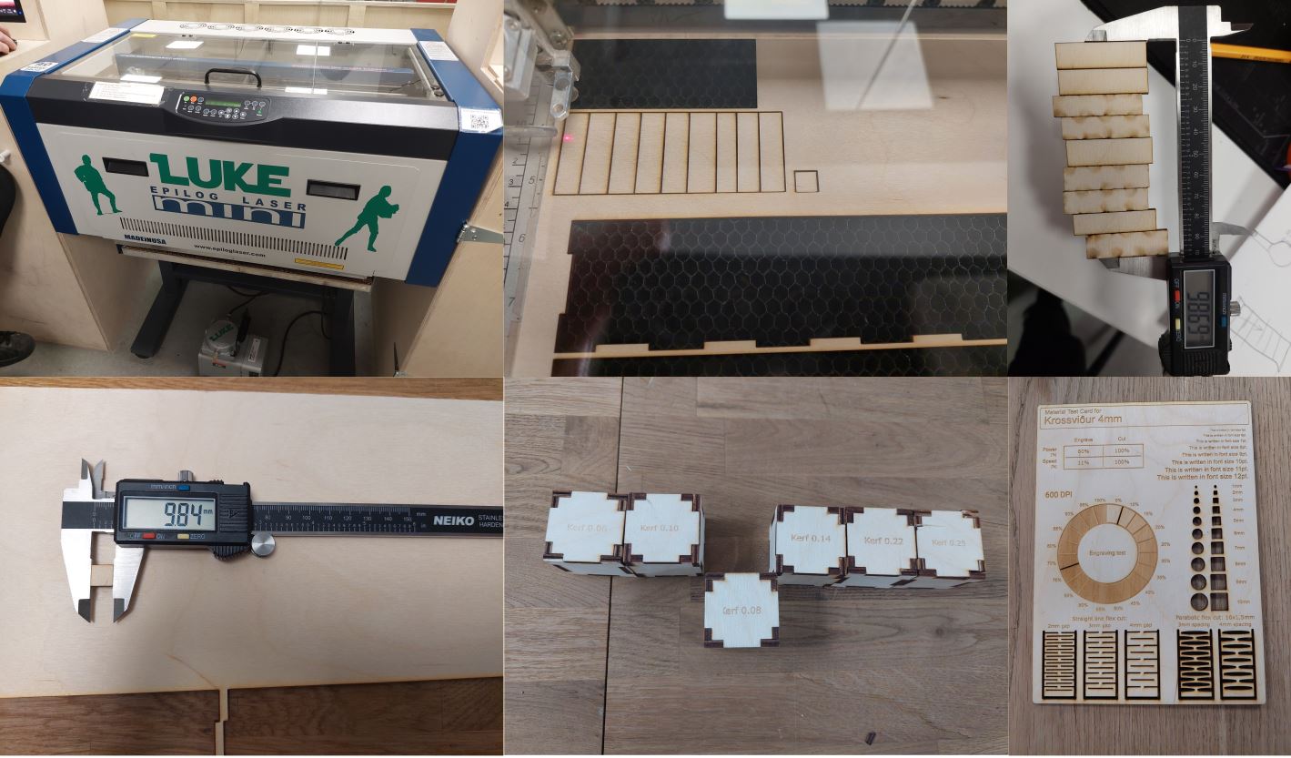
For the kerf test we cut out a 10mm x 10mm rectangle and measured how much material burned off. We also tried a different method where we cut a rectangle with cutting lines in it and seeing how much would burn off. I had already done some kerf test boxes and the 0.08 was the best and by the 10 x10mm test that seems to make sense. By the end we made a laser cutting template for wood just to have in the laser room.
Week 4
Compare the performance and development workflows for other architectures
| Item | Seeed Studio XIAO ESP32C3 | Seeeduino XIAO | Arduino UNO | Arduino Nano RP2040 Connect |
|---|---|---|---|---|
| Processor family | RISC-V | ARM | ARV | ARM |
| Processor | ESP32-C3 32-bit RISC-V @160MHz | SAMD21 M0+@48MHz | ATMega328P | Raspberry Pi® RP2040 |
| Wireless Connectivity | WiFi and Bluetooth 5 (LE) | N/A | N/A | Wi-Fi Nina W102 uBlox module Bluetooth Nina W102 uBlox module Secure element ATECC608A-MAHDA-T Crypto IC |
| Memory | 400KB SRAM, 4MB onboard Flash | 32KB SRAM 256KB FLASH | 2KB SRAM, 32KB FLASH, 1KB EEPROM | SRAM 264 KB AT25SF128A-MHB-T 16MB Flash IC Nina W102 uBlox module 448 KB ROM, 520KB SRAM, 2MB Flash |
| Built-in Sensors | N/A | N/A | N/A | IMU LSM6DSOXTR (6-axis), Microphone MP34DT05 |
| Interfaces | I2C/UART/SPI/I2S | I2C/UART/SPI | I2C/UART/SPI | I2C/UART/SPI |
| PWM/Analog Pins | 11/4 | 11/11 | 6/6 | 20/8 |
| Onboard Buttons | Reset/ Boot Button | N/A | Reset Button | Reset Button |
| Onboard LEDs | Charge LED | N/A | LED | LED |
| Battery Charge Chip | Built-in | N/A | N/A | N/A |
| Programming Languages | Arduino | Arduino/ CircuitPython | Arduino | Arduino |
Andri had compered the Seeed Studio XIAO Series development boards on Andris site so we took 2 of them and I found that same information but for Arduino UNO and Arduino Nano RP2040 Connect. It was very interesting to me because I had to figure out what some of this information means but it gave me some idea what and where to look for information on board in the future.
This table shows the technical specs for Seeed Studio XIAO ESP32C3, Seeeduino XIAO, Arduino UNO and Arduino Nano RP2040 Connect. The Seeduino XIAO and the Arduino RP2040 are both from ARM but the XIAO ESP32C3 is RISC-V and the Arduino Uno is AVR from Atmel. The biggest difference to mention in these boards is the memory, pins and wireless connectivity. The Arduino RP2040 has by far the most flash memory of 16mb, the XIAO ESP32C3 has 4mb and the Arduino Uno and Nano RP2040 have 32kb. The Arduino 2040 has 20 pins, 8 of which can be used as analog, the UNO also has 20 pins but only 6 can be used as analog. Both the Seeed boards have 11 pins but the ESP32C3 can only use 4 of those as analog while the Seeeduino can use 6 pins as analog. Both the ESP32C3 and the RP2040 have WiFI and Bluetooth while the other two do not have wireless networking. The Seeeduino XIAO is the only board to support CircuitPython while all boards support Arduino development workflows.
When it comes down to choosing a board for a project it just depends on what you need. If you need wireless connectivity you would need the ESP32C3 or the RP2040, and if you do not need many pins then the XIAO ESP32C3 would be a good pick. However, if many pins are needed then the Arduino RP2040 would be better. Also, if you need a lot of memory then the Arduino RP2040 would be the best choice. If you need a board that supports CircuitPython then the Seeeduino XIAO would be the only choice. Then it is a matter of the form factor. Both Seeed boards are extremely tiny and would work well with for example wearable devices, just depends if you need a lot of processing power or wireless communication. The Uno is the biggest board and would work fine for development but I would choose another board for production based on size alone. In my personal opinion I like the XIAO ESP32C3 the most as it is tiny and has wireless connectivity, but for bigger projects that need many pins I would go for the Arduino RP2040.Week 5
Test the design rules for your 3D printer(s)
Group assignment week 5 Andri and Hafey performed in Fab Lab Reykjavík. We have both prusa and ultimaker printers. I got the test file from thingiverse here and printed it in both types of printers with their respective slicers. With both printers I put the layer height to 0.15 and infill to 20%. In most areas the Prusa did a better job especially with the overhang, however the square poles were better in the Ultimaker also the Ultimaker ot a little bit of the lettering that stood out whereas the Prusa did not.
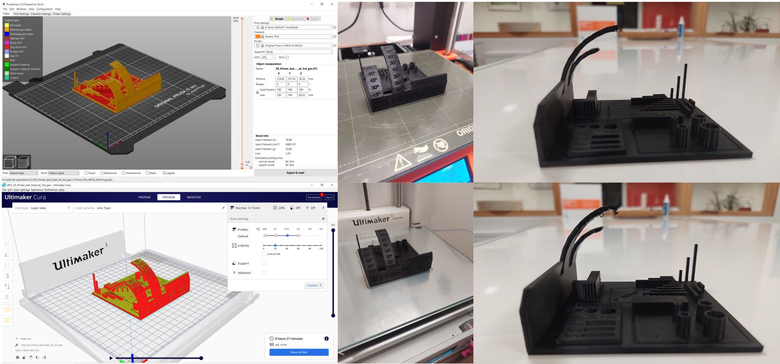
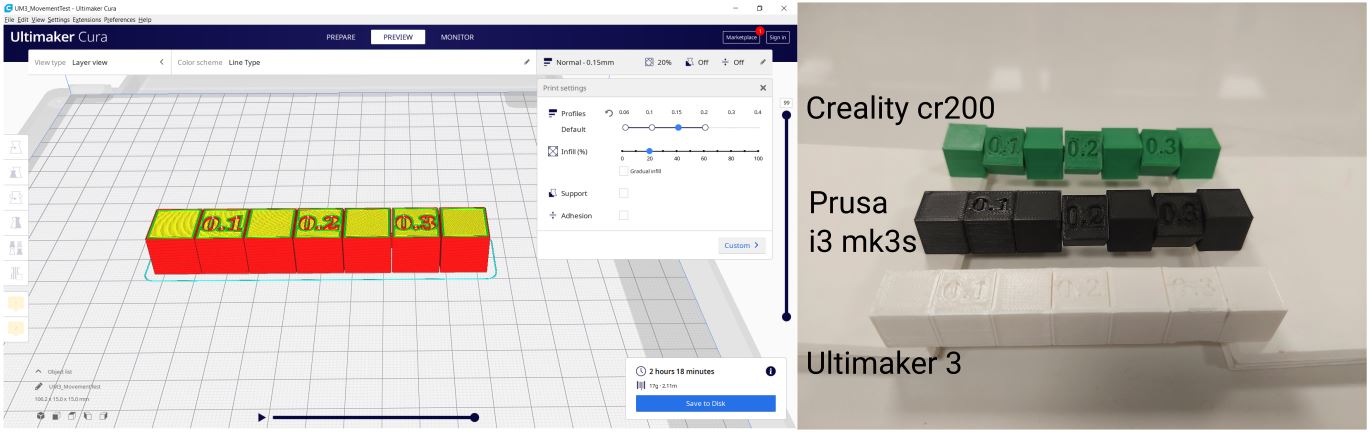
Andri made a file for testing how much space can be between 3D printed parts before they start to get stuck together. The Creality one could move them all but it seems to be a little under extruded, I think the Prusa one is best and the Ultimaker one the worst since you could not move any of them.
Info about printers - Creality cr 200b - Prusa i3 MK3S+ - Ultimaker 3
In Fab Lab Reykjavík we have the three types of printers linked above. We all agree that the Prusa is our favorite.
Links
Week 6
Use the test equipment in your lab to observe the operation of a microcontroller circuit board
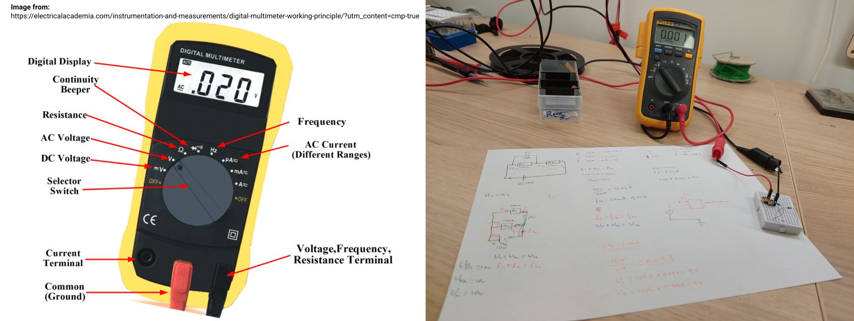
Our college Arnar went over the multimeter with us, we had both used it, but it was good to get a refresher.
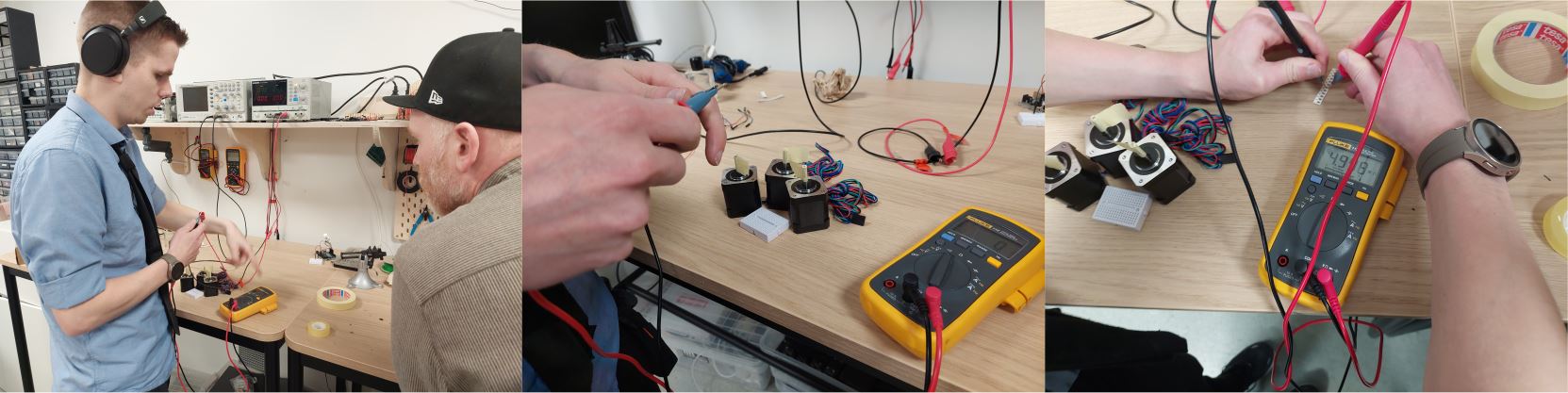
He showed us what we would most likely use the most which was the Continuity beeper to se if there is a connection between spot A and B, Resistance to check how many ohm a resistor is, it is good to always check, they don’t always end up in the draw they are supposed to, it is also always good to know how to check the volts and frequency.
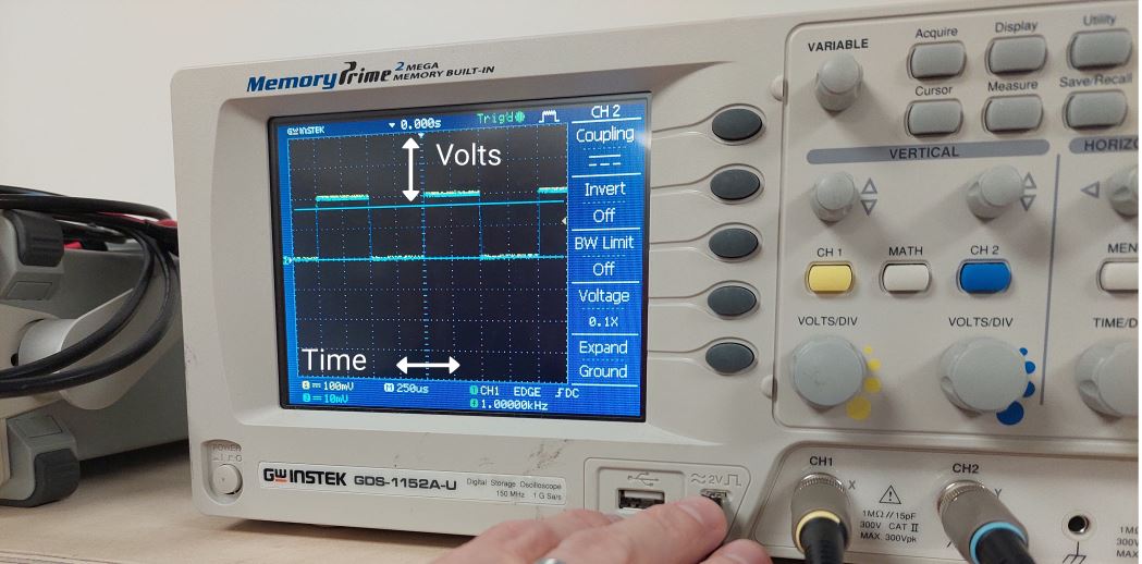
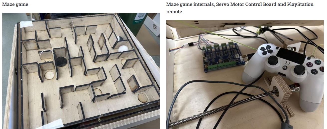
We also got our college Arnar to show us a little on the bit on the oscilloscope, where he connected it to a circuit board that was being used to control a maze game with a PlayStation controller. The signal that is displaying is when the motor is being moved.
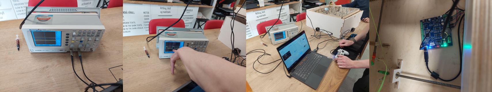
On the screen of the oscilloscope you can see the signal from the board, the sig-sags are the volts and the timing between the volt signals. You can adjust it to see them better and even stop the screen if you need it to be paused to see something better.
Week 7
Do your lab's safety training. Test runout, alignment, fixturing, speeds, feeds, materials, and toolpaths for your machine.
To be able to use the shopbot at Fab Lab Reykjavik you need to take a safety course. The safety course addresses the dos and don’ts of using the shopbot. The safety course also goes over in which order the machine should be used, start the milling motor spin before turning on the vacuum. We do this so we hear the motor spinning. If the motor is not spinning when you turn on the project the shopbot would try to mill the project with no rotating milling bit resulting in breaking bits. After the vacuum is turned on and the shopbot starts the project it may be good to use ear protection but still make sure you hear if the shopbot makes weird noises. You also get training on how to change collets and bits.
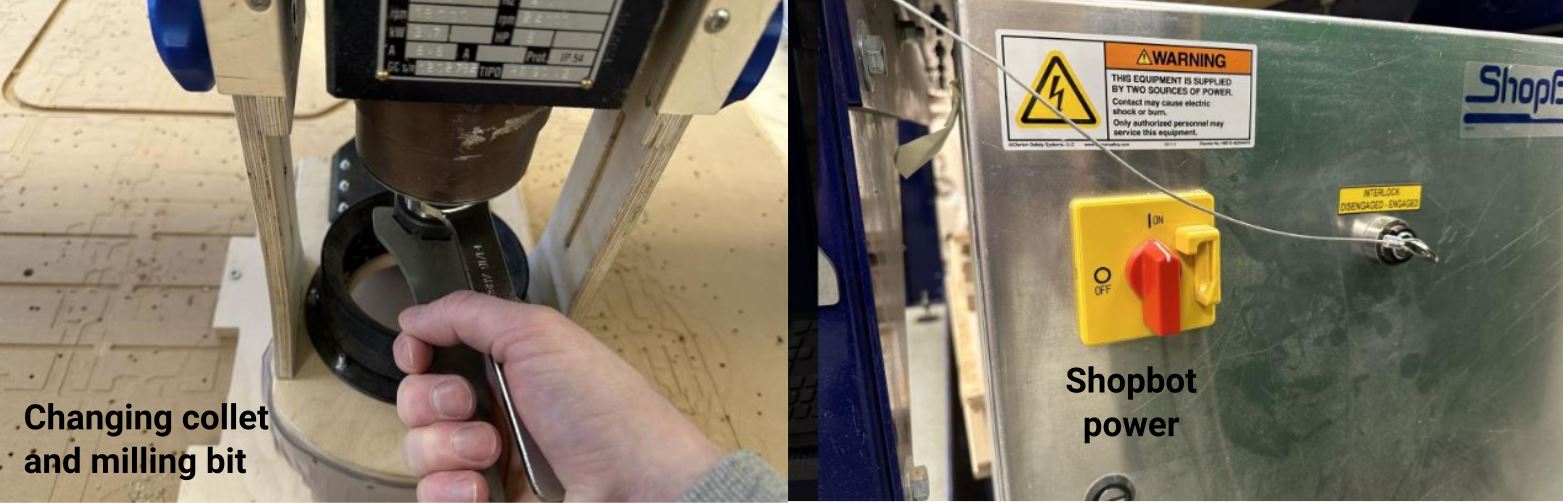
Important takeaway from the safety course is protect you eyes, hair and clothing. Listen and look. And of course know where the emergency stop buttons are placed.

In VCarve I created a 100mm square with a 50mm circle in the middle. I made a pocket toolpath for the circle that went down 5mm. After milling the piece we measured each side to figure out if the Shopbot was accurate enough. The measurements showed the Shopbot was pretty accurate and within acceptable margins of error.
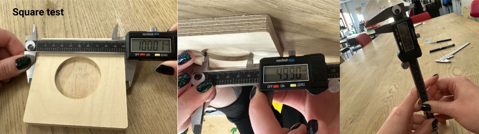
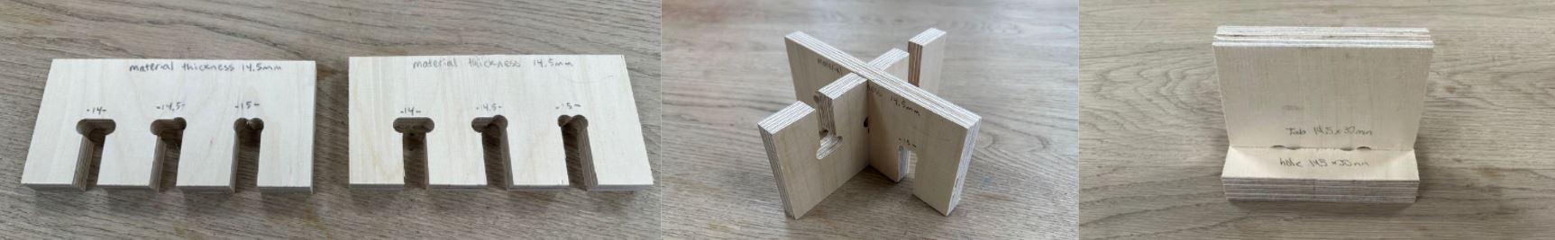
Andri created a comb test similar to the test made for the laser cutter. I created a comb test similar to the test we made for the laser cutter to check the kerf. The material I used was 14.5mm thick and I created three slots to see which slot size would make the best connection. One slot was 14mm, the next 14.5mm and the last 15mm. The 14mm slot was too tight and the 15mm slot was too loose. The 14.5mm slot was the perfect size. Hafey made a DúbbíDúb test to see which tab size and hole would make a good press fit. Using the same size for the tab and hole made a perfect fit.
To calculate the chip load I used the this function: feed rate (mm/min) / (RPM x number of flutes) Using a 6mm endmill with two flutes, 14000 RPM and feed rate at 5000 mm/min the chip load calculates to: 5000 / (2 x 14000) = 0.178
Week 8
Characterize the design rules for your in-house PCB production process: document feeds, speeds, plunge rate, depth of cut (traces and outline) and tooling.
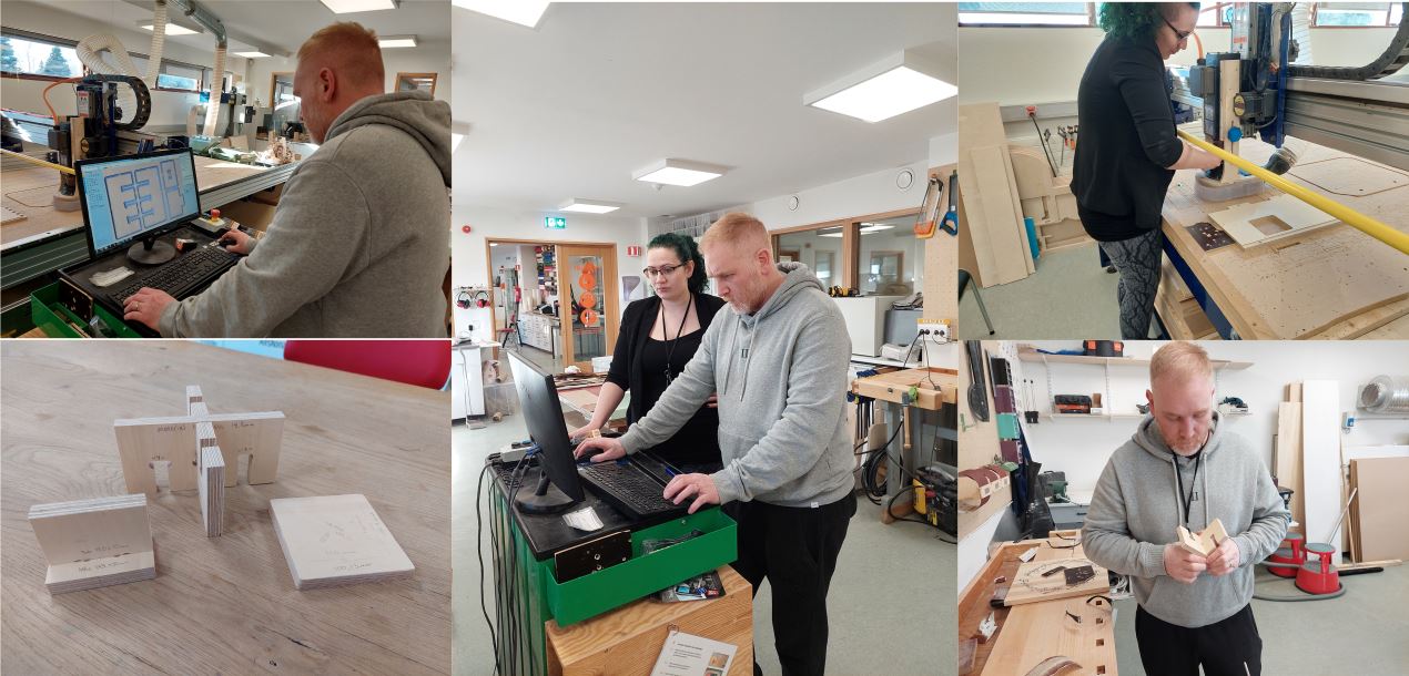
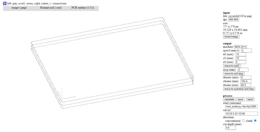
Andri was already familiar with an old version of Mods to mill pcb boards and went over the process with Hafey. Fab modules is run loacally on a raspberry Pi that is connected to the Roland Modela MDX-20. We access fab modules through the local network, in this case by going to a browser and visiting (ip address: port) 10.50.0.22:12345 In fab modules we start by selecting the input format, I always use the image(.png) option. Then you need to select the output format, in my case I select Roland mill (.rml). Finally we select the process, to mill the circuit we use PCB traces (1/64), to cut the outline of the board and through holes we select PCB outline (1/32). On the right hand side of the browser you can mess with the settings for the mill. Start by selecting the machine under output. In my case I select MDX-20. Under output you can see the speed mm/s and the xyz position of the machine. I have been using the default 4 mm/s for the speed. You can input new coordinates for the xyz position and hit the move to xyz0 button. But before hitting the move to xyz0 button you need to go under process and make sure the server field is correct, in my case it should read 10.50.0.22:12345.
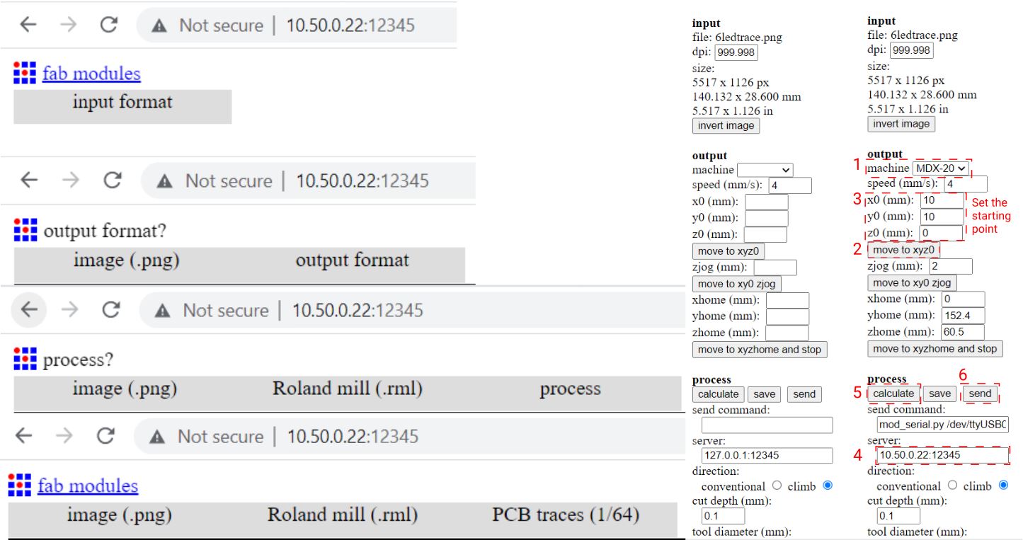
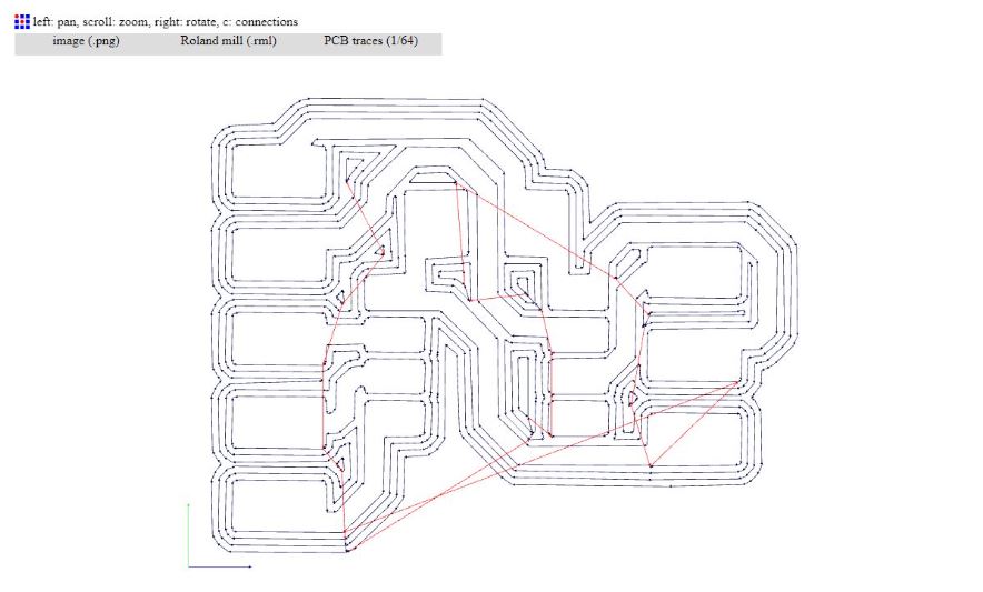
Under process are more settings to consider. Cut depth (mm) is set to 0.1. If the the traces do not mill through the copper make sure that the z axis is properly set and that the board is properly fixed. Then try again with cut depth(mm) at 0.1. If the traces are still not going through the copper you can put the cut depth to 0.11 - 0.13 and you should definitely get through the copper. The next setting is tool diameter(mm). The 1/64 milling bit is about 0.4mm in diameter so I usually keep it at 0.4mm. However, if you have very tight traces, less than 0.4mm you can edit this field to "fool" the machine into milling tight traces. I´ve successfully milled traces that are 0.3mm wide using a 0.4mm milling bit by editing the tool diameter field to 0.3 and hit the calculate button to see if the trace visualization changes. The rest of the settings I usually just keep at default. When you are done with the settings you hit the calculate button to visualize the milling process and finally hitting the send button will start the milling.
To drill holes or cut through the board I open a new browser window and go to the ip address: port, 10.50.0.22:12345. I select the same input format and output format as before but under process I select PCB outline (1/32). The settings for the outline process are very similar to the settings for the traces process. The main difference is that the cut depth is set to 0.6mm per pass, and you can input the material thickness. When you are done with the settings you hit the calculate button to visualize the milling process and finally hitting the send button will start the milling
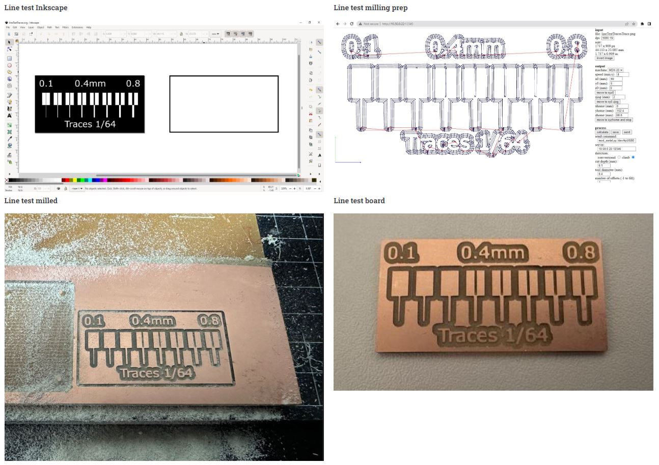
We made a simple line test to see how our milling machine performs. We milled the board using Fab Lab Reykjavik´s Roland MDX-20. We use an old version of Mods to send our design to the mill. The software is run on a raspberry pi and I can access the software through our local network. All lines 0.4mm and above were milled just fine, everything below 0.4mm did not mill. All trace widths look fine, including the finest trace width of 0.1mm.
To mill boards using the Modela MDX-20 you need to prepare the machine. First you need the correct milling bit, I´v been using 1/64 in bit for trace milling and 1/32 for through-milling. To change the milling bits I use the UP arrow on the machine to raise the miling bit and collet. Once the bit is in top position I remove the bit using a hex bit and replace with the correct milling bit. When the correct milling bit is in place I lower the bit using the DOWN arrow button on the machine until it nearly touches the PCB. Then I loosen the collet and make sure it touches the PCB and tighten again. That way the Z-height has been set. Setting the X and Y position is done in browser in the mods software. Under Output I type in the X and Y coordinates and hit the "move to XYZ jog" button to move the milling bit to the correct position. Now a new milling bit is ready and XYZ positions are zeroed.
Week 9
Measure the power consumption of an output device
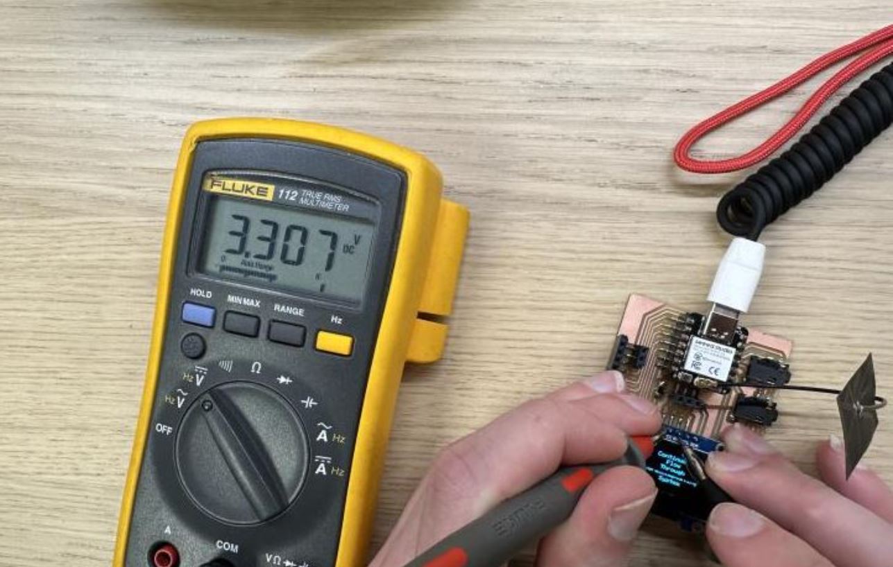
For our group project we measured the power consumption of a SSD1306 OLED display. We used a multimeter and started by measuring the volts. We put the probes from the multimeter on VCC and GND on the SSD1306 OLED display. We got a reading of 3.3 volts which makes perfect sense as the OLED is connected to the 3.3v output from the XIAO.
Next we measured the amps. We wired the display to the GND, SDA and SCL but interrupted the wiring from VCC with the multimeter in between. We got a reading of 0.006 Amps or 6mA.
Using this formula: P = V x I, we calculate the power consumption of the OLED P = 3.3 V = 0.006 I = P * V = 0.0198W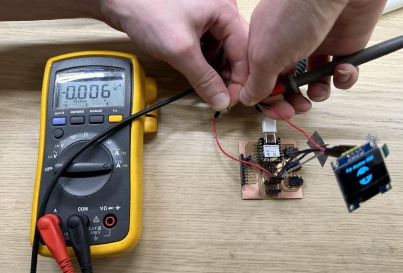
Week 10
Machine week
Group assignment for machine week on group site
Week 11
Probe an input device's analog levels and digital signals
For our group project we probed the input signals of a PlayStation remote, controlling stepper motors. The PlayStation remote is connected to a Stepper Motor Control Board controlling two stepper motors controlling a maze game. The PlayStation remote is hardwired and the probes are connected to the Stepper Motor Control Board. Using an oscilloscope we probed and measured the signals from the PlayStation remote controlling the stepper motors.
The oscilloscope shows how electrical signals change over time by graphing them as waves on a screen. It displays these signals as waveforms on a screen, allowing you to visualize the amplitude (strength) and the frequency (rate of change) of the signal over time. This helps in analyzing and troubleshooting electronic circuits and systems.
Square waves are typically generated by electronic devices called oscillators. These devices produce a waveform that rapidly switches between two voltage levels: a high level (often represented by a positive voltage) and a low level (often represented by zero or a negative voltage). The transition from high to low and vice versa is almost instantaneous, resulting in the square shape. Square waves are commonly used in digital systems and electronics because they have well-defined transitions between high and low levels, making them suitable for representing binary data (0s and 1s) in digital circuits. They are also useful for testing and evaluating electronic components and systems, as their distinct shape makes it easier to detect and measure certain characteristics of the signal, such as rise time and fall time.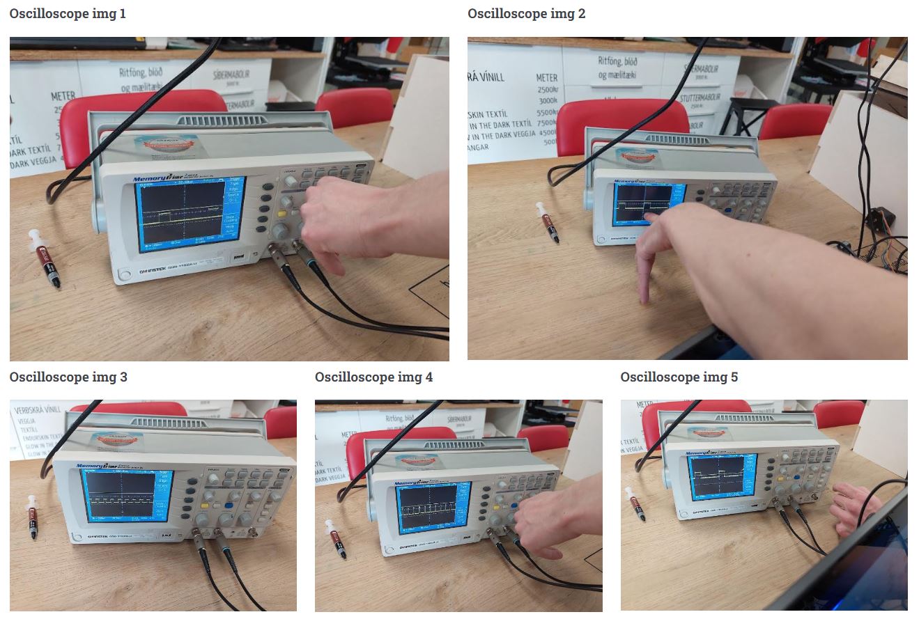
Week 12
Review the safety data sheets for each of your molding and casting materials, then make and compare test casts with each of them
We started by going over our inventory. We had some epoxy but that was pretty old so we weren´t sure if we should use it. So the only materials we had were Dry-Stone Casting Media and construction cement, besides the soap and chocolate we used in our individual projects. We did however go over the safety warnings for using epoxy. The chemicals in epoxy resin systems can affect your health when they come in contact with your skin, or if they evaporate or form a mist or dust in the air you breathe. The main effects of overexposure are irritation of the eyes, nose, throat, and skin, skin allergies, and asthma, so using personal protective equipment is a must.
The safety data for the hydro-stone were printed on the bucket. When the dry-stone hardens it becomes very hot and can cause severe burns if left to harden on bare skin, so let´s avoid that. The dry-stone is very fine powder and can cause irritation to eyes, skin, nose, throat and upper respiratory tract, so using eye protection and a dust respirator is recommended. Keep away from children. DO NOT INGEST. The safety data for the hydro-stone were printed on the bucket. When the dry-stone hardens it becomes very hot and can cause severe burns if left to harden on bare skin, so let´s avoid that. The dry-stone is very fine powder and can cause irritation to eyes, skin, nose, throat and upper respiratory tract, so using eye protection and a dust respirator is recommended. Keep away from children. DO NOT INGEST. The safety data for the cement was printed on the bag. The warnings are similar to the Dry-stone, the cements heats when hardening, it´s a fine powder and can cause irritation to eyes, skin, nose, throat and upper respiratory tract, so using eye protection and a dust respirator is recommended. Keep away from children. DO NOT INGEST.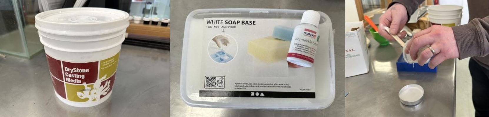
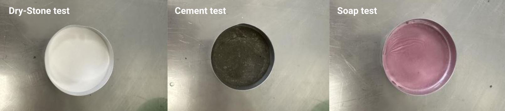
Make and compare test casts with each of them Following the instructions for the Dry-stone we mixed 50 grams of the Dry-Stone powder with 10 grams of water. Always mix the powder into the water, not the other way around. The two were mixed together for a minute before being poured into a container. The Dry-Stone was hard within an hour and was smooth to the touch but still had some water that hadn´t evaporated. Following the instructions for the construction cement we mixed 15 ml of water with 25 grams of powder. Always mix the powder into the water, not the other way around. The mixture was then poured into a container.
Week 13
Send a message between two projects
We took Hafey’s master and nodes and added a node from Andri and changed the code accordingly, it went very well. Links are below the video.
Links
Download Node 1 Download Node 2 Download Node 3 buzzer Download Node 4 groupWeek 14
Compare as many tool options as possible
There are many tools to make a GUI to display and interact with data.
CanvasJS Andri used CanvasJS for his individual assignment. CanvasJS is easy to implement, you simply add the code snippets to you website and point to your data to get visualized data points. CanvasJS is free to use.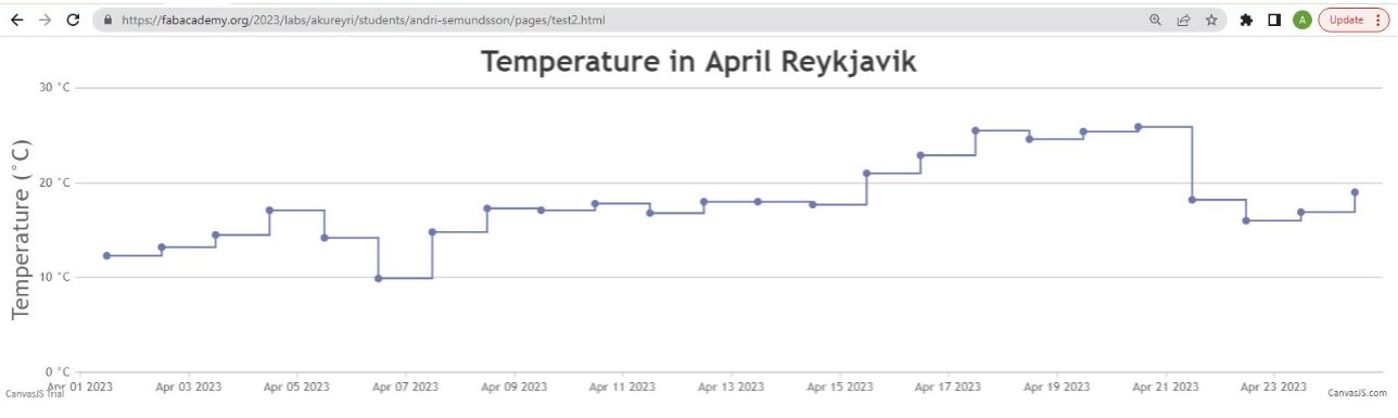
Blynk
Blynk is an Internet of things (IoT) company which provides a platform for building mobile (IOS and Android) applications that can connect electronic devices to the Internet and remotely monitor and control these devices. Blynk has excellent example codes and instructions on how to get everything up and running. Blynk is free to a degree, the FREE plan allows for 2 devices and 1 week of historical data. The PLUS plan has up to 10 devices and 3 months of historical data. The PLUS plan should be enough for most simple projects. They also have a PRO plan which is more for commercial development allowing more devices, widgets and 6 months of historical data. The data can be viewed on their website and mobile app.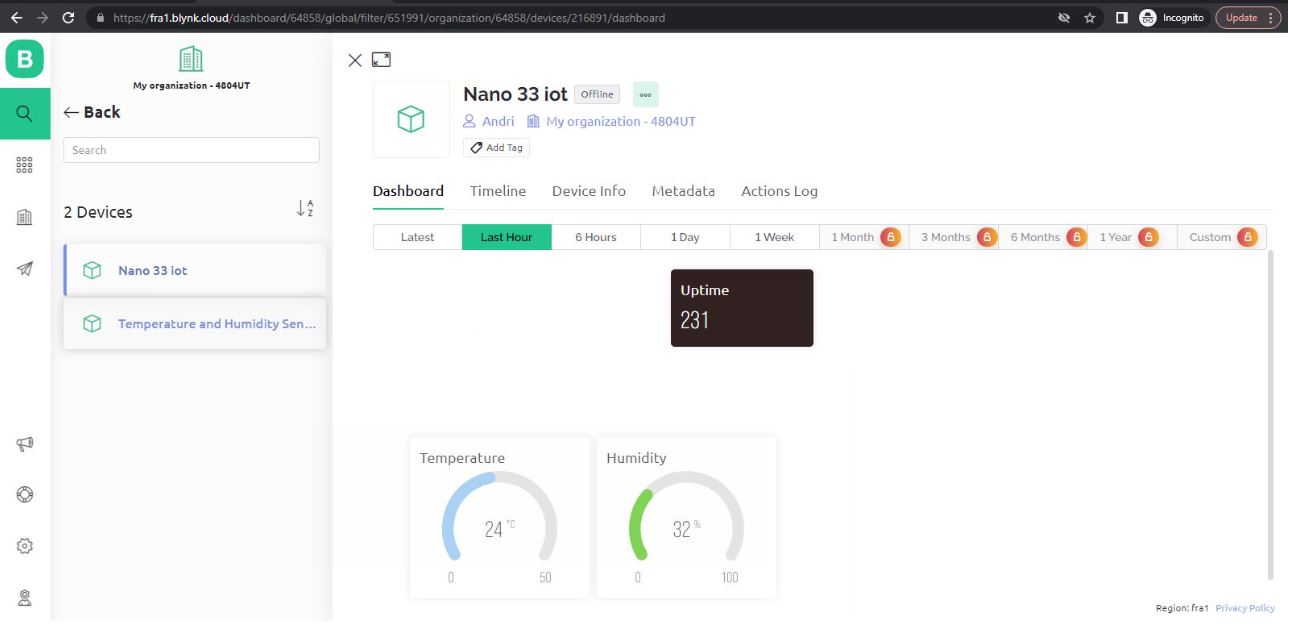
ThingSpeak
ThingSpeak is an open-source software written in Ruby which allows users to communicate with internet enabled devices. It facilitates data access, retrieval and logging of data by providing an API to both the devices and social network websites. There are several code examples and tutorials to get up everything working. The pricing for ThingSpeak depends on the number of messages and channels you use. The FREE plan allows 3 million messages a year and 4 channels. The STANDARD plan allows 33 million messages a year per unit and up to 250 channels per unit. The STANDARD plan is meant for all commercial, government and revenue generating activities with a price at $710 per year. The data can be viewed on their website and through apps.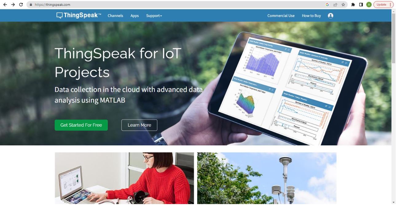
Firebase
Firebase is a mobile and web development platform provided by Google. It offers a suite of tools and services that help developers build and scale applications quickly and efficiently. Firebase provides various features that facilitate tasks such as database management, user authentication, cloud storage, hosting, real-time messaging, and more. It is designed to simplify the development process by providing developers with pre-built components and infrastructure, reducing the need for backend server setup and management. Firebase supports multiple platforms and programming languages, making it versatile for different application requirements. Overall, Firebase empowers developers to focus on building high-quality applications by handling many common backend tasks and providing seamless integration with other Google services. Firebase has differen pricing piers. Spark (Free): Firebase Spark plan provides a generous free tier that allows you to start using Firebase without any cost. It includes a range of features and services, with certain limitations on usage and scalability. Flame (Pay as you go): Firebase Flame plan is a flexible pricing model based on your usage. You pay for the specific services you use, such as Realtime Database, Cloud Firestore, Cloud Storage, Authentication, etc. Pricing is based on factors like data storage, data transfer, authentication operations, and other service-specific metrics. Blaze (Pay as you go): Firebase Blaze plan is suitable for larger-scale projects or applications with high usage. It provides greater scalability and access to advanced features. With Blaze, you are billed based on usage and have access to additional capabilities, such as usage monitoring, expanded quotas, and more.