
Let’s get these boards to talk with each other
to learn / to do
individual assignment:
- design, build, and connect wired or wireless node(s) with network or bus addresses
group assignment:
- send a message between two projects
looking ahead
what I already know
I am kind of used to networking things. For different projects in the past I have used sockets, UDP and serial communication. Both wired and wireless. So I am familiar with the distributed part of it, and I enjoy working on different pieces of hardware to get them to talk to each other.
what I want to learn
I want to dive deeper into I2C, in how it actually works on a basic level. It looks like an understandable protocol, and I want to better understand the code that is involved in both master and secondary.
the process
group assignment
For the group assignment, I teamed up with Benjamin, with Paola also contributing.
Our plan was to have an Arduino Uno and one of our self made PCB’s communicate with each other via I2C. We used Benjamin’s Generic Breakout Board for that.
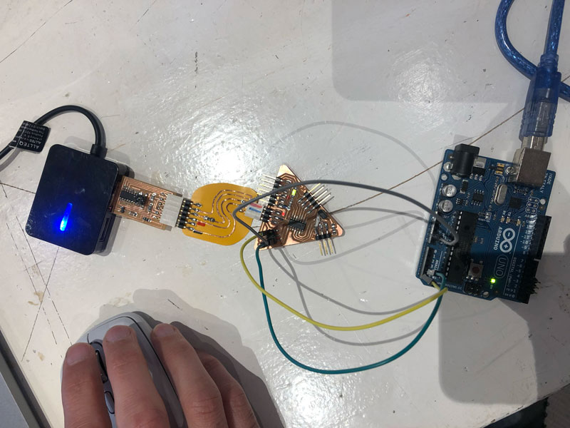 Benjamins Board to the left, connected to the I2C ports of the Arduino
I programmed the Arduino that functioned as the secondary from my computer. Benjamin programmed the Generic Breakout master from his. Below are the most important parts from the code we used. Important is the use of the number 4 as an address for the Arduino. This address is defined on the secondary with Wire.begin(4);
Usually, an I2C device has a fixed address.
Wire.onReceive is an event handler that calls the function receiveEvent whenever data is received. The “while Wire.available()” loop in this functions processes this input byte by byte ( Wire.read() )
|
|
|
|
After some hickups we got the code to work, I started receiving messages in the Serial Monitor on my computer.
individual assignment
My plan is to follow up on the group assignment, and create a small network involving my Color Sensor Board from last week and three Arduino boards that I have lying around.
I want to hook up the Color Sensor board via serial to one of the Arduino’s. The Arduino’s communicate to each other via I2C. Each Arduino will control one LED: A red one, a blue one and a green one. Using the values for RGB that the color sensor sends out, I want each Arduino to shine each LED accordingly. I know that this can also be done with just one Arduino, but then it wouldn’t be a network.
setting it up
Hardware I think I need:
- Color Sensor Board
- 3 Arduino’s
- 3 LED’s (Red, Blue, Green)
- 3 resistors for the LED’s
- Some breadboards, ideally 3
Software I think I need:
- Standard serial communication with RX/TX
- I2C communication
- PWM (for brightness of the LED’s)
To get I general idea for connecting everything, and to be able to show a diagram of my plan, I start with Tinkercad. It becomes clear pretty quickly that one big breadboard is much easier, so I delete the 3 breadboards that I use. And after that I leave Tinkercad to tinker in the real world, as that also is suddenly much easier.
To check if all the boards work as expected, I try a simple led fade program that I find. That proves not to be a problem for the two Arduino Uno’s that I have. The older Arduino NG just blinks the light initially, but I see it just uses different pins for PWM so that is easy to fix.
|
|
getting I2C to work
My next step is to connect the I2C pins, and see if I can control the LED lights from the master. This is the Arduino Uno that currently drives the red LED. I need to connect two pins on all Arduino’s: SDA for data, and CLK for clock. On the Uno’s and the NG, the SDA pin is A4 and the CLK pin is A5.
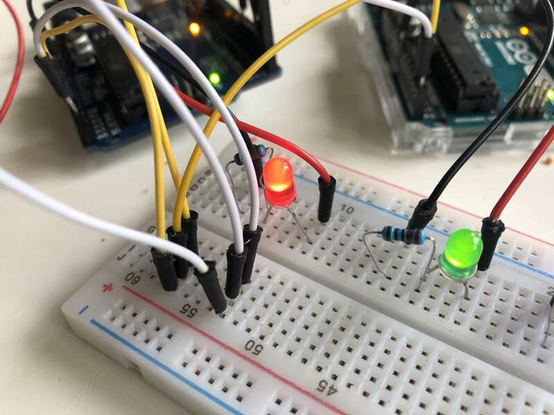 3x3 pins: 3 yellow connected to SDA, white ones connected to CLK
Then it is time to setup the software part of the I2C. For the master, I add a function that sends a value to a secondary. It is based on this tutorial, see the part under “Controller Writer Sketch”.
|
|
The target parameter above refers to the address of the secondary. Usually, an I2C device has its own fixed address that is listed in its datasheet. But for the Arduino’s I can the addresses myself. I use the values 2 and 4 . Sometimes it is unknown what address a device uses. In that case you can try to scan it with this code. There is also a list of addresses of I2C devices available so you can avoid using two devices that have the same address
In the two secondary sketches, I add code to have them listen to the master.
|
|
Then I upload the code to the Arduino’s to see what happens.
It takes some fiddling with the wires, but after a while I have both the green and blue LED under control of the red master Arduino. They fade in and out in sync now.
getting the color sensor to talk
Now that I know that I can control the LED’s on the secondary from the master, it is time to throw the Color Sensor Board in the mix. The color sensor itself communicates via I2C but I can not use this in my setup, as the sensor is talking directly to the microcontroller. So I will have to talk to the microcontroller first. I have connected the RX/TX pins of the microcontroller to headerpins, so Serial is what I will use.
I take the Dual Serial board, and connect the Color Sensor Board on one end, with the UPDI connector. This connects (in my case, with two pins) UPDI and GND. I connect the 5V pin on the other end to the 5V input on my board. I connect the RX/TX pins from the Color Board to the Serial Board as well, so I can tweak the output it sends over Serial.
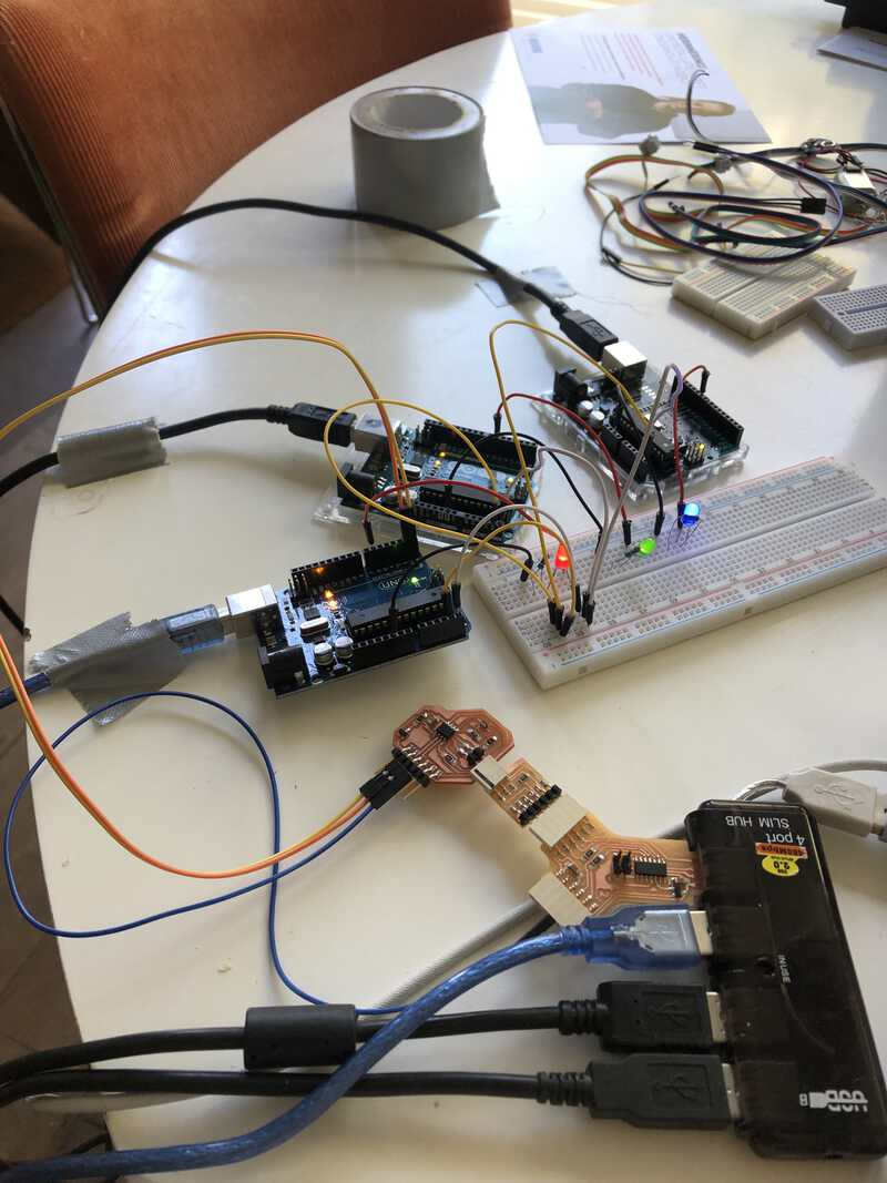 setup with the sensor board connected via the Dual Serial board
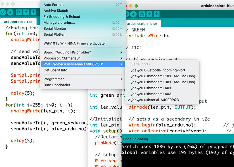 lots of ports in Arduino: two Arduino Uno’s, one Arduino NG and two ports from the Dual Serial board
I modify the program that I used last week (Neils example) so it prints all the color values each on their own line, terminated by a newline.
b:585
w:5379
r:1081
g:1093
b:585
w:5379
r:1081
g:1093
I know that I can use this in combination with the function Serial.readStringUntil() , that I found in this tutorial
Then I connect the RX/TX pins of my board to the TX/RX pins on the red Arduino, to see if I can catch the data there. I see the RX/TX onboard light immediately light up, but I can not upload the new sketch. I think that is because the board is now very busy with receiving all the serial communication, so I undo the RX/TX wires and try to upload again. This time it goes well and when I reconnect the wires, I get the same Serial Output strings, but now on the red Arduino.
After some testing, I realise that Serial.readStringUntil() does not perform as flawlessly as I thought. I seems to miss bytes sometimes, and then gets confused:
// reveiving end gets confused

w:6399
w
---
r:1483
r
---
g:1483
g
---
b881
b
---
w:r:1483
w
---
b:881
9
b
---
r:148483
r
---
b:6399
b
---
r:g:1483
r
---
w:6399
w
---
3
In this thread I read that readStringUntil is a blocking function and should better be avoided. I change it for a piece of code that uses start- and -endmarkers, but not with better results. In the end I just add a delay(100) at the end of the loop, to throttle the stream a bit.
interpreting the sensor data
The next step is to interpret the datastrings for the red, green and blue values, so I can send them to the other Arduino’s or use them on this Arduino.
This is not too complex, I just take the first character to inspect the color, and use a substring to extract the color value. The value I can send to the LED needs to be between 0 and 255, but the sensor gives me values that are far bigger. I check the datasheet to see what the max value is and plan to use a map() function to map this to a range that I can use.
It seems that the values differ per color. I am not sure what the units are, but I think it is Lumen. I check several FabAcademy peers from former years, but most of them use a max value of 6000 for all colors. In my output I have values that are higher. I finally find reliable looking map values in the end project documentation of Nil Peguero:
  r = map(redColor, 5800, 41700, 0, 255);

  g = map(greenColor, 6800, 65535, 0, 255);

  b = map(blueColor, 3710, 20500, 0, 255);
Basically, Nil has taken highest and lowest measurements of each color in different light conditions. After averaging the readings he maps them to values between 0 and 255. This does not work for me though. My light conditions may differ. As the focus of this week’s assignment is passing around data I leave this for now and just use the 6000 max value that everybody uses. I will look into this matter next week in the Interface Programming week.
In the end, I get the sensor to work in the way that I had planned: it sends its data via serial to an Arduino, and the Arduino sends it via I2C to two other Arduino’s. The RGB values however are not really accurate. Partly this is because I use colored sheets to test, and more than anything they provide shadow instead of light. I did not think to add a white LED to the PCB board to illuminate surfaces, so my PCB board is mostly fit to measure the color of light instead of the color of a surface.
looking back
what went wrong, what went well, lessons learned, room for improvement
This week was relatively easy for me, which was very welcome after the past couple of weeks (and in prospect of the weeks to come). I really enjoyed working with different pieces of hardware and get them to talk with each other. I was also happy to use my Color Sensor Board, and using Serial TX/RX to communicate with outside the Serial Monitor of Arduino. I never really thought about the fact that Arduino’s have their own serial input/output pins to use. I was also surprised that even my oldest Arduino has I2C built in.
I still relied heavily on the Arduino development environment, even though I find it cumbersome to work with. It meant I had to be constantly aware to which board (and type) to talk to on which port. It would be nice to use software that uses profiles, or at least remembers the last selected port for a board. I plan to look into Platform.IO in the coming weeks.